A Separator is a type of pressure vessel that is used to separate the gas and liquid from a two-phase mixture. The two-phase separator separates the liquid and gas phases from the mixture.
Pressure vessels are widely used in the process plant industry. Pressure vessels serve various functions such as
short-term hold-up, i.e. day tanks, surge vessels,
pressurized storage storages, i.e. bullets, Horton spheres,
Special purpose vessels such as reactors, columns, and jacketed vessels.
The most common shape of pressure vessels is a cylindrical shell with dished ends. Other types of end closures such as conical, and hemispherical are also used when appropriate. For large pressurized storage, a spherical shape may be chosen. The Standard Engineering codes used for the design of 2-phase separators are GPSA guidelines, and API 12J.
Orientation of Separators
Pressure vessels/Separators can be installed in vertical or horizontal orientation.
Vertical Pressure Vessels
Vertical orientation is preferred to horizontal orientation owing to the following advantages:
Lower plot space required: In most cases length (or height) of pressure vessels is more than the diameter. Therefore, the layout space required is lower when a vessel is placed vertically.
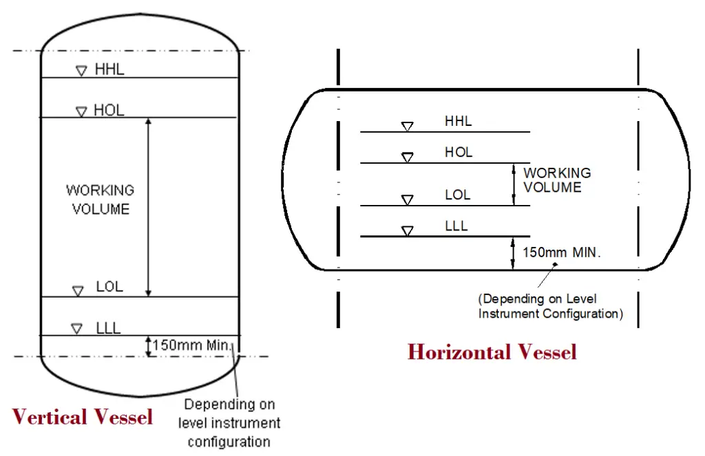
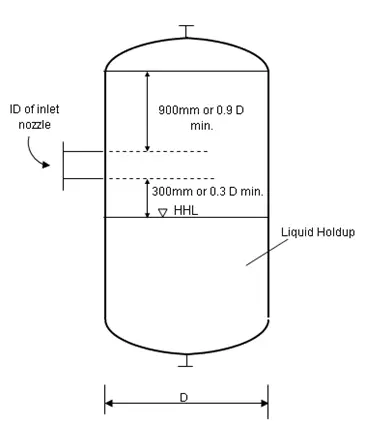
The vertical installation provides better utilization of vessel volume as the working volume between the high and low operating levels. This is illustrated in Fig. 1 below:
Fig. 1: Vertical vs Horizontal Pressure Vessel
Horizontal Pressure Vessels
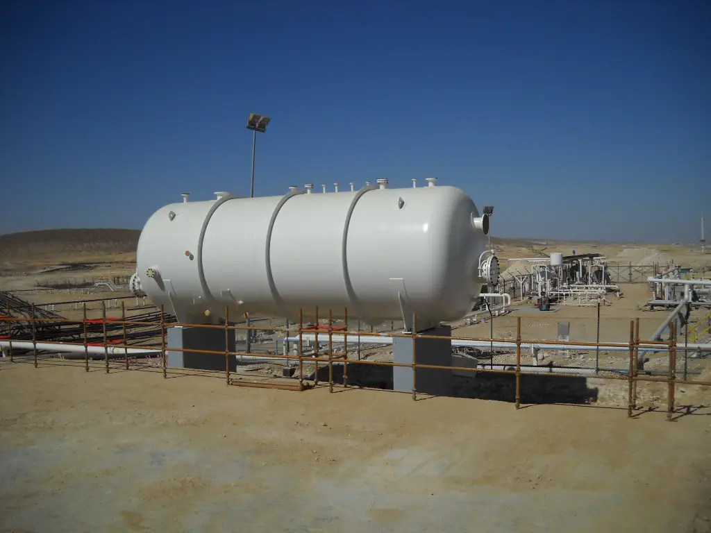
A vessel may be oriented horizontally when higher mechanical strength is needed to support the weight. This is especially important in the case of high-pressure vessels and very long vessels (high L/D ratio). Horizontal vessels can be provided with two or more saddles.
Two-Phase (V/L) Separator Design
Depending on fluid phases the separators can be classified into two groups.
Two-Phase Separator and
Three-Phase separator
Two-phase separators handle two-phase fluids. One is the gaseous phase and the other is the liquid phase. While a three-phase separator can separate out three phases; normally a gas, oil, and water (two liquid phases and one gas phase). In the following paragraphs, we will briefly explore the design basics of two-phase separators.
Selection of Separator: Horizontal or Vertical
As a rule, a vertical drum should be chosen when the ratio of vapor to liquid volume is large (750 or more). The vertical drum is often preferred since the separation efficiency does not vary with the liquid level in the drum. Also, the plot space required is lower for the vertical drum.
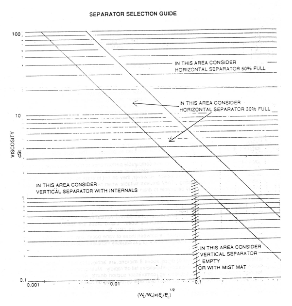
The figure given below (Fig. 2) is used as guidance for the selection of the orientation of separators.
Fig. 2: Separator Selection Guide Chart
Choice of Separator Internals
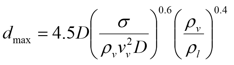
Separator Internals are provided to increase the efficiency of the separator and reduce entrainment. The Internals available commercially is Demister Pads, Vane packs, Multi cyclones, or swirl decks. The size of droplets present in the two-phase flow entering the drum decides the type of internals to be used. Droplet size depends on the flow regime of the inlet pipe. The diameter of the inlet pipe should be selected to avoid dispersed, annular, or mist flow. The approximate size of droplets present in the vapor phase is given by:
Symbol
Description
Units
d
Drop diameter
m
D
pipeline internal diameter
m
g
acceleration due to gravity
m/s2
k
Souder’s Brown proportionality constant
k/s
ρ
density
kg/m3
σ
surface tension
N/m
v
velocity
m/s
W
mass flowrate
kg/s
P
pressure
bar
ν
kinematic viscosity
m2/s
μ
dynamic viscosity
Ns/m2
Subscripts
v
gas/vapor phase
l
liquid phase
Determining Separator Diameter
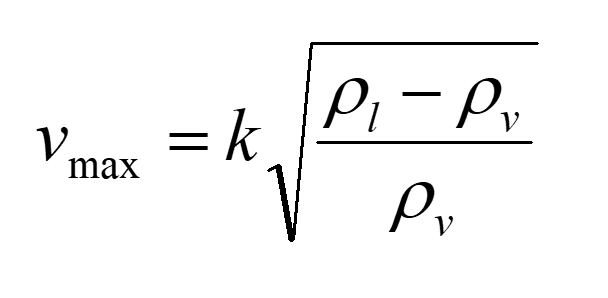
The design methods are based on Souder’s-Brown equation
The maximum allowable velocity of the vapor phase is given by the value of vmax calculated by the Souder’s-Brown equation. The diameter of a vertical separator is calculated based on the value of vmax.
In the case of a horizontal vessel, the full cross-section area for the flow of vapor is calculated based on the value of vmax. This is in turn used to calculate vessel diameter.
Typical Values of Proportionality Constant, k
Different values of the proportionality constant k are applied for the internals and orientation of the separator.
The full form of P&ID is Process and Instrumentation Diagram. This is an engineering document developed by process engineers that shows the piping and other related items for process flow. A P&ID provides a detailed graphical representation of the actual process system that includes the piping, equipment, valves, instrumentation, and other process components in the system. All components are represented using various P&ID symbols.
The graphical representation in a P&ID drawing establishes the functional relationship of piping, instrumentation, and mechanical equipment. P&IDs are one of the most important documents for any project and are crucial in all stages of process system development and operation. This is the most extensively used engineering document and is used by all engineering disciplines like Process, piping, mechanical, civil, HVAC, electrical, and instrumentation.
What is P&ID used for?
A P&ID (Also known as PEFS, Process Engineering Flow Scheme) is a fundamental engineering document that serves various purposes as mentioned below.
P&IDs Provide key piping and instrumentation items along with their proper arrangement.
It serves as a basic document for operation, control, and shutdown schemes.
The piping and Instrumentation diagram provides a basis for maintenance and modification works.
It gives the regulatory and plant safety requirement.
A P&ID drawing serves as a guide for start-up and operational data.
P&IDs are used to develop guidelines and standards for facility operation
It is the basic training document to explain the process details to operation guys, field engineers, and maintenance professionals. The P&ID drawings help them to track the interconnection between the piping and instrumentation and equipment.
A P&ID provides the design and construction sequence for the plants for systematic planning of activities.
They serve as a basis for studying different mechanical and chemical steps to find the root cause if something goes wrong.
It also provides basic information for initial project cost estimation.
Finally, the P&ID drawing provides a common language for discussing plant operations.
Limitations of P&ID
P&IDs being graphical schematic process representations have some limitations like
They are not on a scale, similar to real models.
They are not standardized documents so vary from company to company.
What should a P&ID include?
There is no exact code or standard that dictates what exactly should be included in the P&ID drawing document. That is the reason P&IDs from different organizations vary slightly. Broadly, all P&IDs normally include the following:
All Mechanical equipment with equipment numbers (Tags) and names.
The in-depth details are not included in the P&IDs. Various supporting documents are prepared for the detailed design and description of those items. Normally the following details are not included in a P&ID:
As the Piping and Instrumentation Diagram is not a detailed document, various supporting documents are prepared to complete the overall details of the P&ID. Few of those documents are:
PFD or Process Flow Diagram from which P&ID is generated.
Equipment and Instrument Item datasheets specifying the required details about Equipment or instrument items.
P&ID Symbols
Process engineers use various P&ID symbols while constructing P&ID drawings. All those P&ID symbols are normally described at the start of the P&ID set. For the same design consultant, those symbols are normally constant. One should familiarize himself by studying those P&ID symbols to accurately read the P&ID drawings.
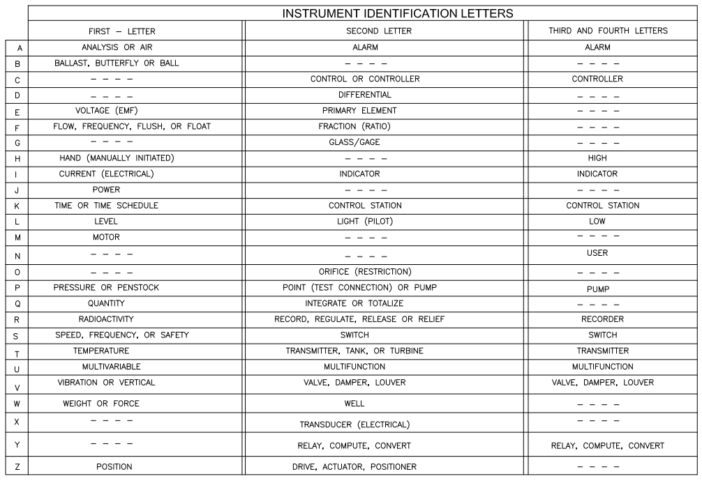
Instrumentation symbols in a P&ID are standardized as per ANSI/ISA’s S5.1 standard. This standard ensures a consistent, system-independent means of communicating instrumentation, control, and automation intent by providing standardized Instrumentation Symbols and Identification so everyone understands.
Four graphical elements are defined in ISA S5.1 for instrumentation. Those are discrete instruments, shared control/display, computer function, and programmable logic controller. The standard also groups them into three location categories as the primary location, auxiliary location, and field-mounted location category. Click here to check all the P&ID symbols that ANSI/ISA’s S5.1 standard provides.
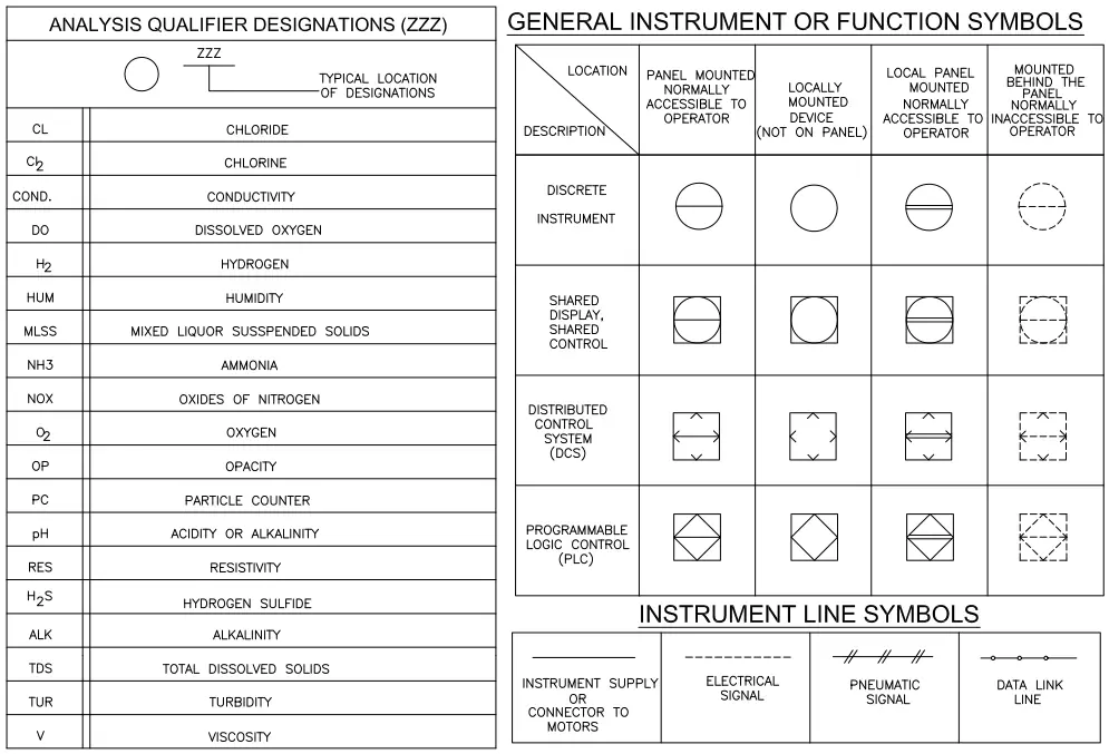
BS 5070 and ISO 10628 also provide a few guidelines and best practices for P&ID symbols. The following images (Fig.1 to Fig. 7) provide an example of the P&ID symbols that are normally used in a typical P&ID.
Fig. 2: P&ID Symbols-General instrument or function symbols
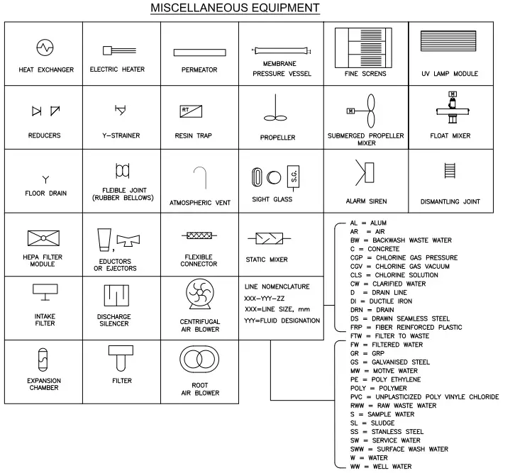
P&ID Equipment Symbols
Fig. 3: P&ID Symbols- Miscellaneous Equipment
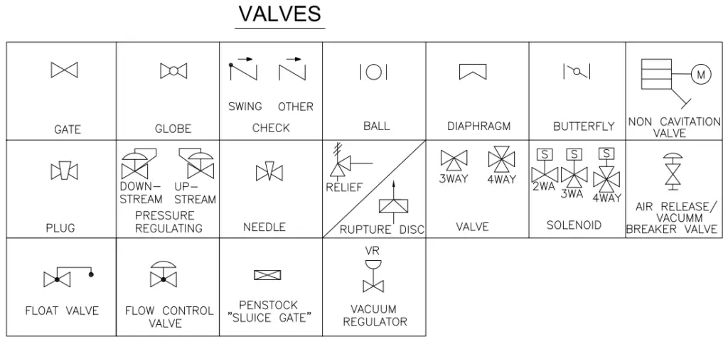
Valve Symbols in the Piping and Instrumentation Diagram
Fig. 4: P&ID Symbols-Valves
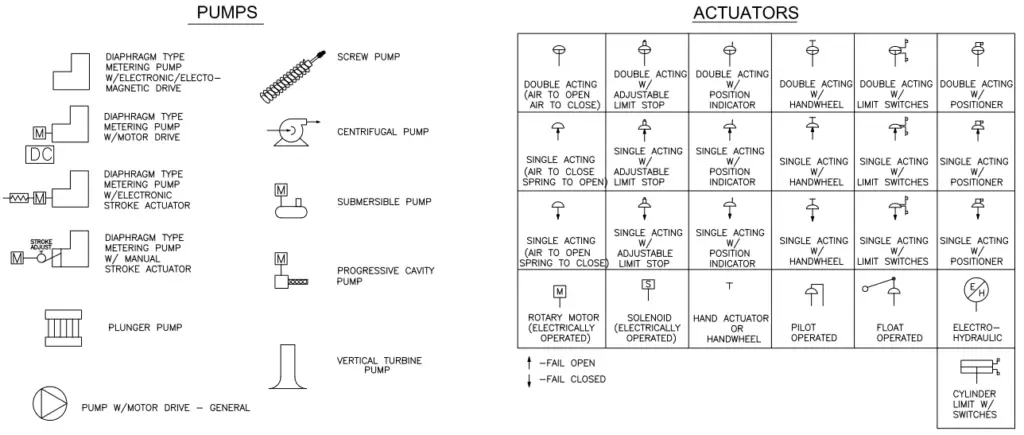
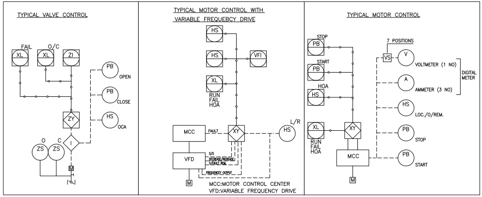
P&ID Symbols for Pumps and Actuators
Fig. 5: P&ID Symbols-Pumps and Actuators
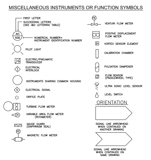
P&ID Symbols for Miscellaneous Instruments and Functions
Fig. 6: P&ID Symbols-Instrument or Function Symbols
P&ID Symbols for Various Control Loops
Fig. 7: P&ID Symbols-Various Control Loop Symbols
Please note that few organizations use the words like P&ID Legends, P&ID Lead sheets, or P&ID Legend drawings in place of P&ID Symbols.
How to Read P&ID Drawings?
Reading or tracing a P&ID drawing to understand the process or design requirements are quite easy if the P&ID symbols are properly understood. So, it is always preferable to go through the P&ID symbols repeatedly, those are provided in the initial 4-5 pages of the P&ID sets. Once that is ready open the P&ID and start reading it.
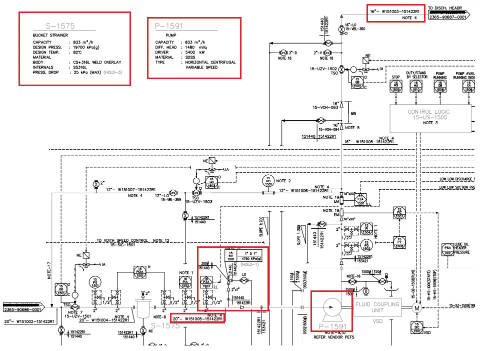
Fig. 8: How to Read P&ID
Here, we will learn how to read P&ID with a simple example. Refer to Fig. 8 which shows a part of a P&ID. We will read part of the suction and discharge line of pump P-1519.
As can be seen clearly the suction line is coming from a different P&ID drawing and entering into the bucket strainer S-1575.
The line number, pipe size, material spec, etc of the line are provided clearly.
The line number changed from the strainer outlet, one PSV connection is attached before the pump suction reducer.
After the reducer, the material specification is changed and then the line is connected to the pump suction flange.
In a similar way, the pump discharge flange is connected to the discharge line, Line number, size, PMS, etc. are mentioned.
So in a similar way, we can easily read the P&IDs as per our requirements and extract data to use for our purpose.
Related notes are provided wherever required. We have to refer to those notes for knowing any specific requirements.
A Gate valve is a linear-motion manual valve that has a vertical rectangular or circular disc that slides across an opening to stop the flow that acts as a “gate”. Generally used for isolation purposes fully open or closed, Gate valves are not suitable for throttling service because the high-velocity flow will cause a partially open disk to vibrate and chatter and will hasten the erosion of the disc and seating surfaces.
Functions of Gate Valve
The open/close flow is achieved by moving the gate of the gate valve into or out of the fluid-flow stream. The flow of the fluid through the valve can be in either direction. Gate Valve is commonly used in refineries and petrochemical plants where pressure is low, and less used in upstream facilities due to high operating pressure, long on/off times (requiring many turns of the handwheel to open it or to close it), and severe environmental conditions.
A full port gate valve provides a full line size (equal to pipe dimensions) thus resulting in a minimum-flow pressure drop, On the other hand, A Reduced port gate valve smaller than the line size (Flow area less than the pipe) causes a slightly high-pressure drop than a full port.
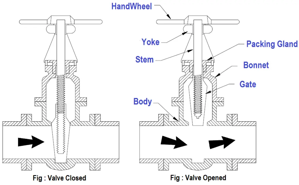
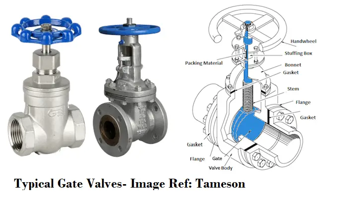
Gate Valve Parts
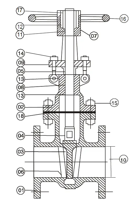
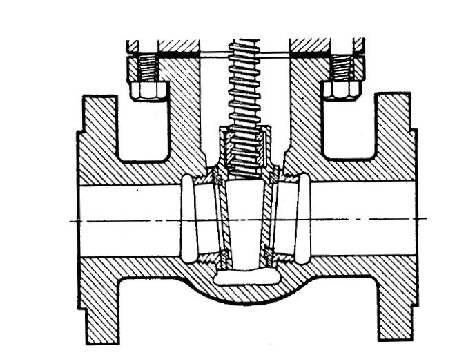
Refer to the below-attached figure (Fig. 1) which shows the main components of a gate valve.
Fig. 1: Full-Port Gate Valve
The items in Fig. 1 as per the corresponding numbers are given below:
Body
Bonnet
Wedge
Stem
Gland
Seat ring
Yoke
Packing
Gland Flange
Valve port
Yoke Bush
Lantern
Back Seat Bushing
Gland eyebolts & nuts
Bonnet bolts & nuts
Hand Wheel
Hand Wheel nut
Bonnet Gasket
There are three main parts in a Gate valve: body, bonnet, and trim.
The valve body is connected to piping or equipment by means of flanged, welded, or screwed connections.
The bonnet contains the moving parts which are connected to the body with bolts.
The valve internal parts (removable and replaceable) that come in direct contact with the fluid are termed Valve trim which consists of the stem, the gate, the disc or wedge, and the seat rings.
Types of Gate Valves/ Gate Valve Types
Gate valves are divided into a number of classes, depending on their disc and type of stems. Gate Valves are classified by:
I. Gate Valve types as per Type of Closing Element:
1. Parallel disk Gate Valve:
Parallel disk gate valves consist of two discs that are forced apart against parallel seats by a spring at the point of the closure. The most famous type is the knife gate valve which has a flat gate between two parallel seats (an upstream and a downstream seat) to achieve the required shut-off. The application of a parallel gate valve is limited to low pressures and low-pressure drops.
Fig. 2: Parallel Disk Gate Valve
2. Solid-Wedge Gate Valve:
The solid, or single wedge gate valve is the most widely used and the lowest cost used in the process industry for oil, gas, and air services. The purpose of the wedge shape is to introduce a high supplementary seating load. Solid-Wedge Gate Valve can be installed in any position, suitable for almost all fluids and practical for turbulent flow services.
In some situations, the valve cannot be reopened until the system temperature reheats the valve; this phenomenon is known as “Thermal blinding”. Wedge gate valves can be further described as inside screw or outside screw patterns. Solid wedge gate valves in the waterworks industry are popular as Sluice valves.
Fig. 3: Solid Wedge Gate Valve
3. Flexible Wedge Gate Valve
A flexible wedge gate valve employs a flexible wedge that is a one-piece disk with a cut around the perimeter (the cut varies in size, shape, and depth). Thermal expansion and contraction entail no problems in such kinds of gate valves as the disk is able to compensate for this and remains easy to open. Flexible wedge gate valves are widely used in steam systems to prevent thermal blinding.
Fig. 4: Flexible Wedge Gate Valve
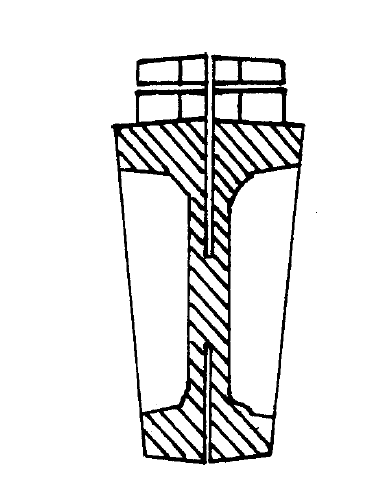
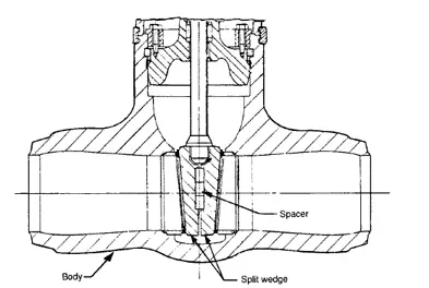
4. Split Wedge Gate Valve
Split wedges of this type of gate valve are made in two separate halves. This allows the wedge angle between their outer faces to fit the seat (self-adjusting and self-aligning to both seating surfaces).
Fig. 5: Split Wedge Gate Valve
5. Double-disc Valves
In these types of valves, the gate is in the form of two discs that are forced apart against parallel seats by a spring. this provides tight sealing without relying on fluid pressure, making this type of valve particularly suitable for steam duties as well as handling gases and light oils.
6. Bellows Seal Gate Valves
Bellows seal gate valves are designed to minimize exposure to harmful substances through valve-stem leakage. The bellow is a metallic device capable of sealing between the valve stem and the bonnet to prevent the escape of the system fluid to the atmosphere. The bellows take the form of convolutions that can move linearly. During operation, the bellows eliminate the leak path to the atmosphere.
II. Gate Valve types as per Type of Stem:
1. Rising Stem Gate Valve with Outside Screw
This type of gate valve is also known as OS & Y type (Outside steam and York). The stem rises while opening and lower while closing the valve offering an indication of the gate valve position. The stem threads never contact the flow medium (not subject to corrosion/erosion).
Fig. 6: Rising Stem gate valve
2. Non-Rising Stem Gate Valve
Also known as the Insider screw Valve, The stem of the non-rising stem gate valve is threaded into the gate. The hand wheel and stem move together and there is no rising or lowering of the stem. The stem is in contact with the flow medium.
Fig. 7: Non-Rising Stem gate valve
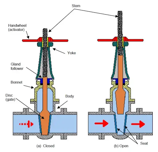
Working of Gate Valves
The working of a gate valve is quite simple. When the gate of the valve is lifted from the flow path, the valve opens and when the gate again returns to its position, the gate valve closes. This gate movement is achieved by manually turning the hand wheel. The hand wheel rotates the valve stem and the internal threaded mechanism provides a vertical movement of the gate. As the hand wheel is turned more than one full cycle to fully open or fully close the gate valve, they are also known as multi-turn valves. Electrically actuated gate valves are available but not cost-effective.
Actuation of Gate Valves
Manual actuation of gate valves is invariably by screw and handwheel. The screw mechanism may be exposed or protected and the screw rising or non-rising. A variety of materials for the working parts is offered by some manufacturers.
Power actuators are very often fitted when the gate valves are difficult to access and are operated frequently. automation and semi-automation control schemes make extensive use of actuators.
Slow disc movement in operation, it takes time to fully open or fully close.
Lapping and grinding repairs are difficult to accomplish.
May create noise and vibration when partially open.
Prone to Seat and Disk wear.
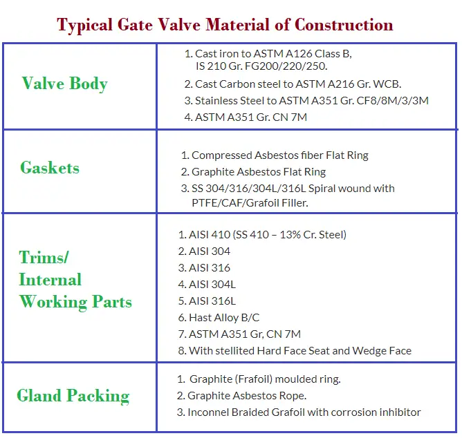
Gate Valve Materials
Various types of materials are used for gate valve construction. Typical common materials used are cast carbon steel, cast iron, ductile iron, gunmetal, bronze, alloy steel, stainless steel, and forged steel. Brass and PVC gate valves are used for plumbing services. The material selection for gate valves primarily depends on fluid service and its design temperature. The following table provides a typical example of common materials used in Gate valve construction.
Fig. 8: Gate valve materials
Applicable codes and standards for gate valve design
The following codes and standards govern the design specification of gate valves:
Valve Design: API 600/ API 602/ BS5352/ API 603/ API6D/ IS780 /BS 1414 / BS 14846
Valve Pressure Testing: API 598
Valve Pressure Temperature Rating: API B16.34
Face-to-Face Dimensions: ANSI B16.10
Flange Drilling: ANSI B16.5 / ASME B 16.47/ BS 10 Table / DIN /IS /JIS Standards
Butt/ Socket Welded End: ANSI B16.25 and B16.11
Screwed End: ANSI B 1.20.1 (BSP/NPT)
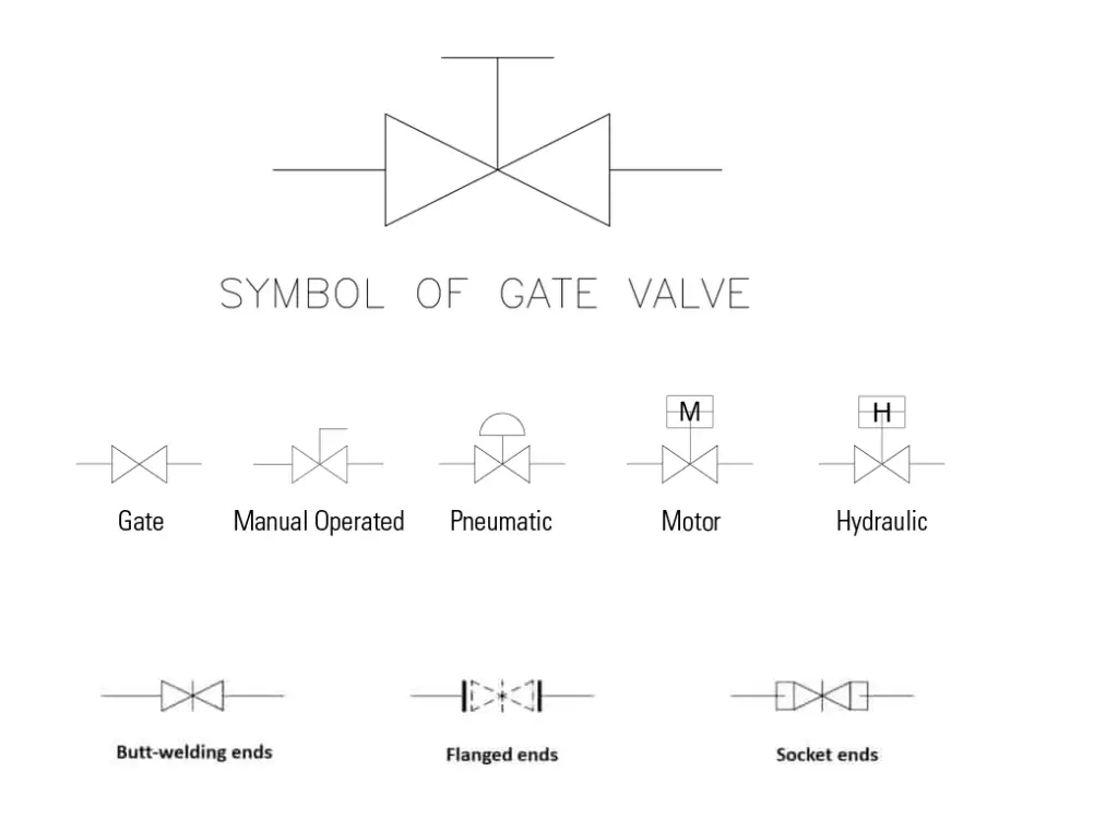
Gate Valve Symbols
The gate valve symbols used in the different organization varies a little bit. Normally any one of the following three types of gate valve symbols given in Fig. 9 is used as a gate valve symbol.
Fig. 9: Gate Valve Symbols
Gate valve vs Ball Valve
Both the gate valve and Ball valve are widely used for isolation services in the oil and gas industries. However, there are a few differences between the gate valve and the ball valve. Some of such differences are listed below in a tabular format for reference:
Parameter
Gate Valve
Ball valve
Working Principle
Gate valves control the valve using its gate. When lifted up, allows full flow, and when down, no flow.
Ball valves feature a stem and a ball with an opening inside. When the opening is lined up with the pipe by turning the control lever fluid can pass, otherwise, the valve is off.
Cost
Gate valves are Relatively cheaper
Ball valves are comparatively Costlier.
Turning of lever or hand-wheel
Gate valves feature a Multi-Turn mechanism.
Ball valves are Quarter-turn valves.
Weight
The weight of the Gate valve is normally less than the ball valve for the same size and rating.
Ball Valve weights are comparatively more than gate valves.
Shut off capabilities
The shut-off capabilities of gate valves are not at par with ball valves.
Comparatively better than gate valves; more reliable.
Surge Probability
As the operation of a gate valve is slow, less probability of water hammer.
Ball valves are more prone to water hammer or surge creation.
Vibration probability
Partially open gate valves cause vibration or noise
The possibility of noise production is less in ball valves.
Operating Space requirement
The operating space requirement for gate valves is usually less.
More space is required to operate a ball valve.
Visual Clue for on/off position
No clue from the outside, it’s simply guessing.
Easy to understand if the ball valve is in the open or closed position.
Hopefully, by now all the Caesar II users are aware that the latest version of the piping stress analysis software Caesar II version 12.0 has already been released by Hexagon. Like every year they routinely update the code requirements and resolve user difficulties that appear in the earlier version of the software. In a similar way, they have come with new changes and updated capabilities in the latest edition called Caesar II version 12.
Even though there are many pipe stress analysis software like Autopipe, Caepipe, Rohr2, Start-Prof, etc, Caesar II is the most widely used software having a major market share in the piping stress analysis software domain. In the following table, I will present a comparison between Caesar II version 12 and Caesar II version 11.
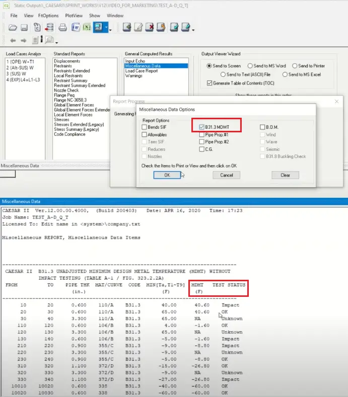
Fig. 1: MDMT Test requirements in Caesar II Version 12
Parameter
Caesar II 2019-Caesar II Version 11
Caesar II Version 12
Piping Code Editions
1. Caesar II 2019 complies with the process piping code ASME B 31.3 2016 edition 2. It complies with liquid pipeline code ASME B31.4 to the 2016 edition 3. ASME B31.8 piping code to the 2016 edition 4. Canadian Z662 piping code to the 2015 edition
1. Caesar II version 12 complies with the latest edition of Process Piping Code ASME B 31.3-2018 2. Complies ASME B31.4 pipeline code to the 2019 edition 3. ASME B31.8 piping code to the 2018 edition 4. Canadian Z662 piping code to the 2019 edition
Structural Database
This version OF Caesar II complies with the older version of AISC; ASIC- 1989
Structural databases have been updated to AISC 2017
License Manager
HASP Key. Transitioning to Intergraph Smart Licensing (ISL).
Fully compatible with ISL, a cloud-based licensing system. This version no longer supports Smart Plant License Manager or HASP keys.
Year Branding
Caesar II version 11 is also known as Caesar II 2019
Year branding has been removed from the CAESAR II version name. So there is no Caesar II 2020; It’s only Caesar II version 12.
In-Plane and Out-plane SIF
–
More detailed information on the use of in-plane and out-plane stress intensification factors (SIFs) is added with respect to FEA translation. Additional information on the local coordinate definitions is also included.
Material Database
–
The Russian material database is updated.
Interface with AFT Impulse
No interface with AFT Impulse
Dynamic surge analysis becomes easier as files can be directly imported from the AFT Impulse software.
MDMT Report
Not Available
Minimum Metal Design Temperature (MDMT) data is added to the database (Refer to Fig. 1) to check the impact test requirements. The software checks the requirement.
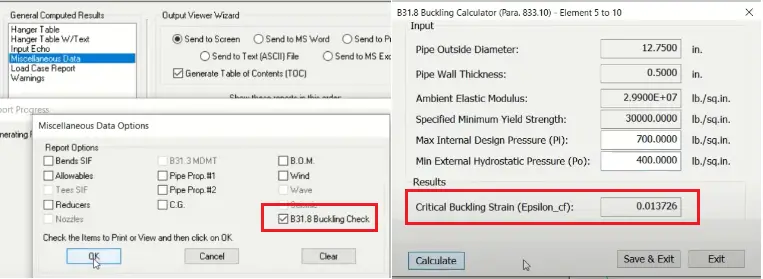
Buckling Check as per ASME B 31.8
Not Available in this version
Buckling check following ASME B 31.8 (Refer to Fig. 2) code has been added in Caesar II version 12. This provides strain values to calculate the buckling and lateral instability of piping elements.
Caesar II Help files
All help files are available offline in the local drive.
All help files are now online in the latest version of the software. It provides improved search, custom book creation, and quick updates.
Caesar II Version 12 vs Caesar II Version 11
Fig. 2: B 31.8 buckling check-in Latest edition of Caesar II
The Caesar II owner Hexagon PPM has released one video explaining the enhanced capabilities for the latest edition, i.e Caesar II Version 12. The same has been embedded here for your reference.
Tutorial video explaining What’s new in Caesar II Version 12
Piping systems are the backbone of many industrial processes, from oil and gas to water treatment and chemical manufacturing. Given their critical role, the integrity of these systems is paramount. Piping inspection is a systematic approach to ensuring that pipes and their associated systems are safe, reliable, and compliant with regulations.
What is Piping Inspection?
Piping Inspection is a comprehensive task that is performed following client/company-specific inspection documents. The main aim of the piping inspection is to ensure plant reliability, reducing probable errors, and thus safely operating the plant throughout its design life.
All plants are designed for a predetermined design life (normally 20 years for process piping). Periodic inspection help plants to operate with safety and efficiency.
Even after attending and completing various courses related to piping, most of the fresh graduates and professionals face difficulties in understanding the procedures when it comes to real-life jobs.
Considering the stigma, a simple way to understand the basic unique procedures that are to be followed during the fabrication and installation of carbon steel pipes is discussed in this article.
For performing piping inspections, there should be a client-approved Inspection and Test Plan, or ITP, in place prior to the commencement of any job activities. This shall be prepared with reference to the piping design code and project specifications.
Piping design codes like ASME B31.3 PROCESS PIPING will be the design code for designing piping by the engineering team for the project.
Different types of design codes are available as per the project and product requirements. Understanding the codes and standards along with the particular project specification will provide basic ideas regarding the scope of work being executed.
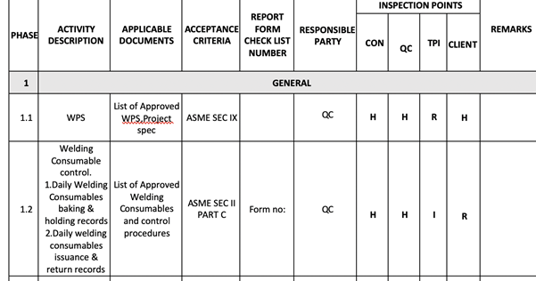
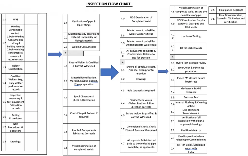
According to the requirements of the design code, the drawings will be developed and the same design code will be reflected in the drawings. All the construction procedures will be shortlisted with different intervention points as shown in the below Fig.1
Fig. 1: List of Piping Inspection Points
What is the Inspection and Test Plan or ITP?
An ITP covers all the construction activities that are being carried out during and after the construction. Learning and understanding ITP along with the construction procedures and Method of statement for specific activities will give a wide range of understanding regarding the job being executed. The Inspection and Test Plan must meet the requirements of the design code (ASME B 31.3 for process piping).
Welding procedure specification or WPS shall be approved by the client prior to the commencement of any welding jobs. CSWIP and AWS-certified inspectors are preferred as inspectors or quality engineers for inspection-related jobs. Further to the approval of WPS welder qualification tests will be carried out based on the project requirements on the welding positions, process, and types. Only these welders who successfully pass the qualification test based on visual and Radiographic Testing reports can be used for all the project-related welding activities. Welder IDs signed by all parties shall be prepared and issued to the welder that shall be available with the welder during working hours.
Various certifications like API 570, API 650, Bgas, NACE, and Level 3 courses are available in the market to strengthen the requirements of a professional for a company.
Initially, after the approval of the above-said documents by the client, inspections shall be performed based on the ITP. No inspections or documents will be generated other than the ones mentioned in the ITP.
Inspection of Piping and Component Materials
Piping and Component Material inspection is the next step of inspection normally done by the quality personnel when a material related to the project is received at the site. The below points as a minimum are to be checked during the material inspection:
Material purchased is from the client-approved manufacturer or vendor
Heat numbers provided in the materials are matching with the Material Test Certificates provided prior to the inspection.
Quantity of the material with reference to purchase order and delivery note.
Reviewing of Material Test certificates with reference to project specification, design code, and drawings.
Proper stacking of the materials.
Material inspection reports shall be generated with all the requested data like Material grade and type, quantity, Heat number, Material certificate number, and inspection status.
Once the materials are approved by the client it can be issued for construction.
Different Types of Piping Inspection
Fit-Up Inspection
Initially, the piping activities will commence with the fit-up inspection. This shall be carried out based on the approved isometric/weld map generated from the P&ID.
During the fit-up inspection, the joint number, date, spool number, drawing number, and sheet with revision shall be checked. The heat number of the material shall be noted for preparing the fit-up report. Taper gauge, Hi-lo gauge, cam gauge, and measuring tape will be used for checking the fit-up gap between the joints and for checking the dimension of spools. Further to the acceptance of fit-up the spool or joint can be released for welding.
Welding Inspection
Mostly GTAW and SMAW welding techniques are most commonly used for pipe welding. The welding inspections will be carried out in different stages by a certified welding inspector and the reports shall be generated with material grade and specification, heat number, drawing number with sheet number and revision, joint type, welding process, welder number, and dates.
Once the joints are completed will proceed with the RT i.e, radiography testing as per the percentage of NDE recommended in the design code and project specification.
Piping routing consists of elbows and fittings. Other than the weld joints flanged joints will be available based on the engineering requirements considering the stress analysis. Pipe supports and wear pads along with any other attachments shown in the drawings shall be checked twice.
Visual Inspection
Visual inspection is the most fundamental type of inspection. It involves examining the exterior of pipes for signs of wear, corrosion, leaks, and other visible defects. While it cannot detect subsurface issues, it is a valuable first step in identifying potential problems.
Destructive Testing
In certain scenarios, destructive testing may be necessary to evaluate the material properties of piping. This includes tensile testing, impact testing, and metallurgical analysis. While it provides detailed insights, it is not commonly used for routine inspections due to its invasive nature.
Piping Inspection Punch Lists
Once the welding activities and installation of piping spools or the system are completed a pre-hydro walkthrough will be conducted in order to find the balance/pending jobs. These are normally considered punches that are commonly grouped into two types, punch A & punch B. Punch A items consist of direct welding items, and punch B can be closed after the hydro tests. No direct welding shall be done in the piping system after the completion of hydro testing.
Hydro-test Package
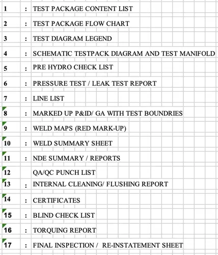
After attending the punch A items, the spools can be released for hydro testing. A test package shall be prepared, not limited to the below-listed items.
Fig. 2: Piping Hydro Test Package Items
The test pressure and holding time will be confirmed subject to the project specification and design code.
Water will be filled into the pipe spools with a pump connected through a test manifold with pressure gauges, safety relief valves, and proper venting facilities. A water test certificate shall be attained prior to the filling of water along with the blind checklist, i.e. the list of blind flanges that are being used for hydro testing.
Understanding the above list will provide a basic idea regarding the hydro test.
Note that a hydro test is done in order to confirm the weld joints’ integrity and to ensure that the parent material is free of any leakage.
Bolt tightening with a torque wrench shall be done for the flanged joints. After draining the water, flushing the lines with water and air blowing shall be done in order to dry the lines.
Note that valves are not installed prior to the hydro test, inline valves are installed after the hydro test and cleaning process as the testing pressure and design code for valves are different.
The spools or piping system can now be released for blasting and painting as per the project requirements. A final walkthrough shall be conducted in order to confirm the installation of all the valves and instruments in the piping system are in place as per the P&ID.
Piping Inspection Flow Chart
The following figure shows a sample piping inspection flow chart.
Fig. 3: Piping Inspection Flow Chart
Codes and Standards for Piping Inspection
There are various international codes and standards that provide guidelines for piping inspection. Some of those codes are listed below for reference:
API 570, Piping Inspection Code
API RP 574, Inspection Practices for Piping System Components
API RP 577 Welding Inspection and Metallurgy
API RP 578, Material Verification for New and Existing Alloy Piping
API RP 571 Damage Mechanism Affecting Fixed Equipment in the Refining Industry
Developing an Inspection Program
Risk Assessment
A thorough risk assessment identifies potential hazards associated with piping systems. This process helps prioritize inspection efforts based on factors like system criticality, operating conditions, and historical data.
Inspection Schedule
Developing a comprehensive inspection schedule is crucial for maintaining piping integrity. Factors to consider include:
Age of the system
Operating conditions
Type of fluid transported
Previous inspection results
Documentation and Reporting
Maintaining detailed inspection records is essential for compliance and future reference. Inspection reports should include:
Inspection methods used
Findings and measurements
Recommendations for repairs or further action
Follow-up inspections and timelines
Common Piping Defects and Their Causes
Corrosion
Corrosion is one of the most significant threats to piping integrity. It can be caused by:
Chemical reactions: Interaction of the pipe material with transported fluids.
Environmental factors: Moisture, temperature fluctuations, and soil conditions can accelerate corrosion.
Cracking
Cracks can result from stress, fatigue, or improper installation. Common types include:
Stress corrosion cracking (SCC): Caused by the combined effects of tensile stress and a corrosive environment.
Fatigue cracking: Resulting from repeated loading and unloading cycles.
Leaks
Leaks can occur due to several factors, including:
Worn-out seals and gaskets
Erosion from fluid flow
Improperly installed fittings or connections
Mechanical Damage
Mechanical damage can arise from external forces, such as impacts from equipment or natural events (e.g., earthquakes). Regular inspections can help identify and mitigate these risks.
Hope, the above-mentioned details will provide some basic ideas to beginners regarding the sequence and structure of piping inspection. Overall, piping inspection is a critical component of maintaining the safety and reliability of piping systems across various industries. By understanding the importance of inspections, employing the right methods, and adhering to industry standards, organizations can mitigate risks and ensure the longevity of their piping systems.
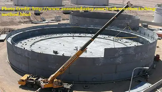
Storage Tank Erection: Conventional vs Jacking Method
Two types of storage tank erection methodology have become widely accepted and popular. The first one is the Conventional Method of Tank Erection & the other is the Tank Jacking method. Both of these tank erection methods are accepted by the API 650 and the constructor. The selection of the tank erection method basically depends on the site location or workshop where we are making these tanks.
There is a popular myth that API 650 guides us to adopt the tank erection methodology. But that is not true. API 650 only guides us in the design, fabrication, welding, hydro testing & inspection of storage tanks.
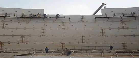
Conventional Method of Tank Erection
In conventional methods, cranes are used for tank erection as a sheet-by-sheet method. At first, the bottom and annular plates are erected. Then the lower course shell is erected and finally, the upper course shell is erected. Refer to Fig. 1 which shows an example of a double-deck floating roof Tank erection by the conventional method. Suppose there are a total of 9 shells in a Tank so the tank erection sequence shall be 1st shell coarse, 2nd shell coarse, 3rd, and then in last 9th shell coarse.
Fig. 1: Double deck floating roof tank erection by a conventional method
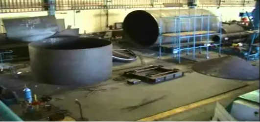
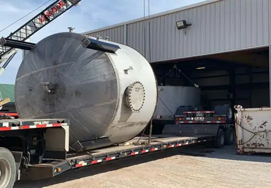
In the case of a small diameter Tank, the tank is fabricated at the workshop and then brought to the site by a trailer for erection. But the handling should be proper to avoid buckling, bending, and any damage.
Fig. 2: Tank erection by the conventional method.
In the case of Shop fabrication, the tank fabrication, erection, & assembly is done by EOT (electric overhead traveling) crane at the shop and then shifted to the site by a trailer.
Fig. 3: Tank Fabrication at shop
Fig. 4: Mobilizing fabricated tank to the construction site
Tank Erection by Jacking Method
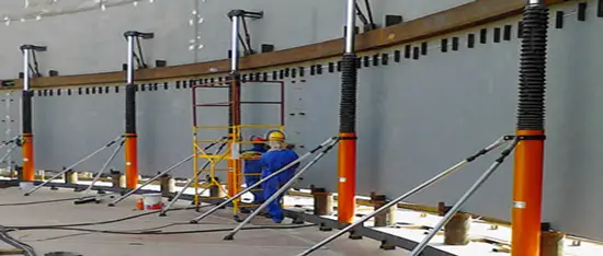
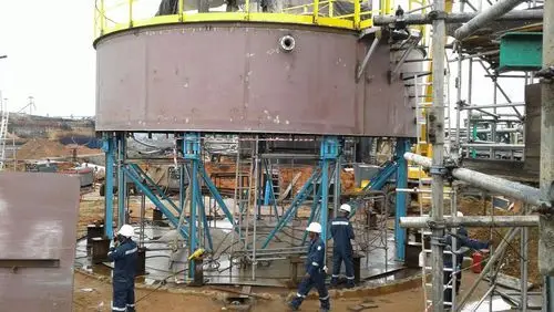
A jacking method is an advanced form of tank erection. The jacking method uses the technology of the Swedish Company Bygging Uddemann AB. A number of hydraulic Jacks are placed inside the tank to be erected. Refer to Fig. 5. In recent times this method is widely used in all developed countries.
A system of hydraulic pressure hoses interconnects the hydraulic jacks which are energized by the action of a hydraulic pump.
Fig. 5: Tank Erection by Jacking Method
This method is just the opposite of the conventional method. The construction sequence is just the reverse of the conventional one. If there are a total of 9 shell courses, the erection in the jacking method will start from the 9th, then the 8th, 7th, and in the last 1st shell course will be erected.
The number of hydraulic jacks is decided based on the total weight of the roof & shell courses except for the bottom courses. Standard practice is to keep a 3000 mm distance between two jacks. However, the number of hydraulic jacks can be increased to meet additional wind load. Fig. 8 shows a typical jack used for tank erection.
Tank Jacking Procedure
The following steps are followed while erecting tanks by jacking procedure:
Tank pad to be checked and tolerances to be verified.
Since jacks are to be mounted on the annular plates, these need to be placed.
Annular plate joints are to be aligned and welded.
Next, erect the floor plates and align the joints to complete the welding of the bottom seams.
After that, Erect the top 2 courses. Align properly and weld. All the works on these two courses including the erection of the curb angle, wind girder for Floating Roof Tanks (or) roof structure, and roof for Cone Roof Tanks, hand railing, etc to be completed.
Next, Place the hydraulic jacks along the circumference of a circle drawn about 100 mm from the shell plate circle. The maximum arc distance between the two Jacks shall not exceed 3000 mm.
Jacks are available in 8 T / 12T capacities. So arrange hydraulic jacks of predetermined quantities before starting the erection. Anchor the jack supporting columns to the base plate.
When, the sub-assembly consisting of the top 2 courses, roof structure/roof (or wind girder) railing, etc. is lifted, erect the shell plates of the third course from the top, after lifting the entire subassembly to the required height.
Align the vertical joints and weld. Next, the sub-assembly is lowered to complete the alignment and welding of the girth seam.
The hydraulic jacks can be released and lowered after the alignment of the girth seam,
In a similar way, erect the other shell courses till all courses are erected.
Finally, Align the shell to the bottom joint and check for the verticality of the completed tank. Weld the shell to the bottom joint.
Now, all other balance works like fixing and welding of shell manholes, nozzles, etc. can be completed.
Various terms are used while erecting tanks as mentioned below:
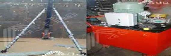
Fig. 6: Stay Pipe and Powerpack machine
Power Pack Machine (Fig. 6): This Machine is used to lift the Jack. This machine Pumps the oil to Jack through the hose pipes to lift the jack.
Stay Pipes (Fig. 6): Also known as supporting pipes; These pipes provide support to jack and trestle pipes. Basically, these pipes are supporting the vertical trestles to maintain verticality.
Trestle Pipes (Fig. 7): These are the vertical members in the Jacking system that carries loads of Jacks. While installing this assembly we need to take extra care of these vertical members so that the verticality of the Tank is maintained. Jacks Move over the Trestles by teeth. These get support from base plates in the Tank bottom.
Fig. 7: Example of Trestles
Difference between the Conventional and Jacking Methods
The main differences between the conventional tank erection and jacking tank erection methods are provided in a tabular format below:
Fig. 8: Typical Jack for Jacking Method
Conventional Tank Erection Method
Tank Erection by Jacking Method
Suitable for all types of tanks with any diameter and height
Large diameter tanks with higher plate thickness requiring double-sided welding are not possible to erect by this method. Not fully feasible for double-wall tanks.
Very good dimensional control is possible: Shell and bottom shapes obtained can be close to the designed dimensions.
Dimensional control is comparatively less.
Erection time is comparatively more
Erection time is less.
Safety issues as working at height
Safe erection as working at ground level. So lower risks.
Resource requirement is more, hence more costly
Economical erection.
Possibility of wind damage while erection.
Protective tank roofs and wind girders eliminate the possibility of wind damage.
Inspection Access is difficult
Easily accessible
Lower productivity
Better productivity
High-capacity cranes are required
The involvement of high-capacity cranes is comparatively less.
Difficult operation with less efficiency
Smooth operation with high efficiency
Conventional Method vs Jacking Method
To summarize, the tank erection methodology by jacking method has many advantages over the conventional ones which include easy to operate, safe and reliable, accurate control of the weld gap and the height of the lifting rod, good quality of the project, and providing an outstanding economic benefit.