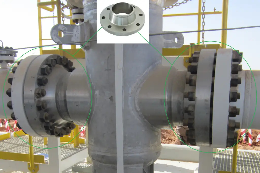
A pipe flange is a circular disc-shaped piping component that attaches to a pipe for blocking or connecting other components like valves, nozzles, special items, etc. After welding, piping flanges are the most popular pipe joining methods. Wherever, any dismantling of components is required for maintenance, inspection, replacement, or operational purposes piping flanged joints are preferred.
Pipe flanges use bolts and gaskets in between to ensure leakage-free piping joints. Piping flanges are selected based on pressure-temperature rating and pipe class following ASME B16.5 or ASME B16.47 standard. However, custom-made pipe flanges can be manufactured but are not preferred in industries. Piping flanges are the best alternative to welding or threading and are manufactured by forging.
Types of Flanges
Various types of pipe flanges are used in industries. They can be classified based on
- Pipe Attachment /Connection
- Flange Facing
- Pressure-Temperature rating
- Codes
Pipe Flange Types Based on Pipe Attachment or Connection
Depending on the type of pipe connection the piping flanges can be classified as below:
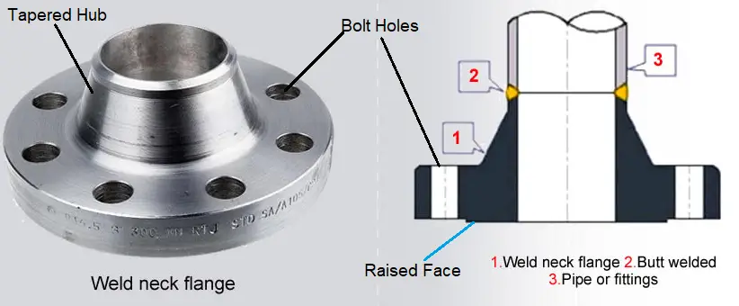
Weld Neck Flanges
Weld neck pipe flanges are suitable for high-temperature and pressure applications. The neck of the pipe flanges is welded to the neck of the pipe.
The main features of weld neck flanges are:
- Weld neck flanges (Fig. 1) have a long tapered hub between the flange ring & weld joint; Hence, these flanges are referred to as high hub flanges. This hub provides a more gradual transition from the flange ring thickness to the pipe wall thickness and the ID matches with the pipe ID. This smooth transition of weld neck flanges reduces high-stress concentrations and consequently increases the strength of the flange.
- As Pipe ID and Flange ID match, there are no flow restrictions. At the same time erosion and turbulence are eliminated.
- Weld neck flange is considered the best-designed butt welded flange available in the piping industry. The welding area, being sufficiently away from the face avoids undue distortion.
- This type of flange is attached to the pipe by having a butt weld which can be radiographed if required.
- Weld neck flanges are suitable for extreme service conditions to handle repeated bending from line expansion, contraction, or other external forces.
- This type of flange is recommended for the handling of costly, inflammable, or explosive fluids where failure or leakage of a flange joint might bring disastrous consequences.
- The pipe Schedule number and I.D. or O.D. must be provided while ordering weld neck pipe flanges.
- The welding neck flange needs accurate alignment of bolt holes before welding.
- However, Weld Neck flanges (Fig. 2) are expensive as compared to other flange types.
- Weld neck flanges require more space and are bulky. Highly skilled manpower is required for the fabrication of welding neck flanges.
- Weld Neck Flange is available in all sizes & it can be Flat Face, Raised Face, or Ring Type Joint type.
- Butt-weld fittings like elbows, tees, or reducers can be directly welded to the weld neck flange without requiring any pipe spool in between.
Slip-On Flanges
Slip-on pipe flanges are shorter in length than the weld neck flange so can be used where there is a space constraint. The inside diameter of slip-on flanges is slightly larger than the pipe OD and so it can slide over the pipe. They are secured to the pipe using two fillet welds from inside and outside. The Slip-on type of flange is widely used in lower temperatures and pressure applications because of its low initial cost. However, their life span is around one-third that of the weld neck flange.
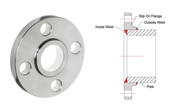
The main features of slip-on flanges are:
- The strength of the slip-on flange (Fig. 3) is around two-thirds that of a corresponding welding neck flange.
- The slip-on flange is not recommended for corrosive and/or critical services.
- The use of slip-on flange is usually limited to class 300 (refer to para on pressure-temperature rating) and design temperature not exceeding 500° F.
- Proper alignment of bolt holes must be ensured before the welding of this type of flange.
- The joint in a slip-on flange can not be subjected to radiography due to the absence of a full penetration weld.
- slip-on flanges are not suitable for cyclic loading services.
- Less skilled manpower is required during installation due to the use of fillet welds. The fillet weld size on the inside of the flange is equal to the pipe wall thickness, or 6mm; whichever is lower.
Lap Joint Flange
A lap joint flange is basically a two-component flange assembly. It has a stub end and a backing lap-joint ring flange. A pipe is butt-welded to the Stub End and the Lap Joint is free to rotate around the stub end. The face of the stub end acts as a raised face of the flange and can be of different materials to save cost. Only the stub end comes in contact with the fluid.
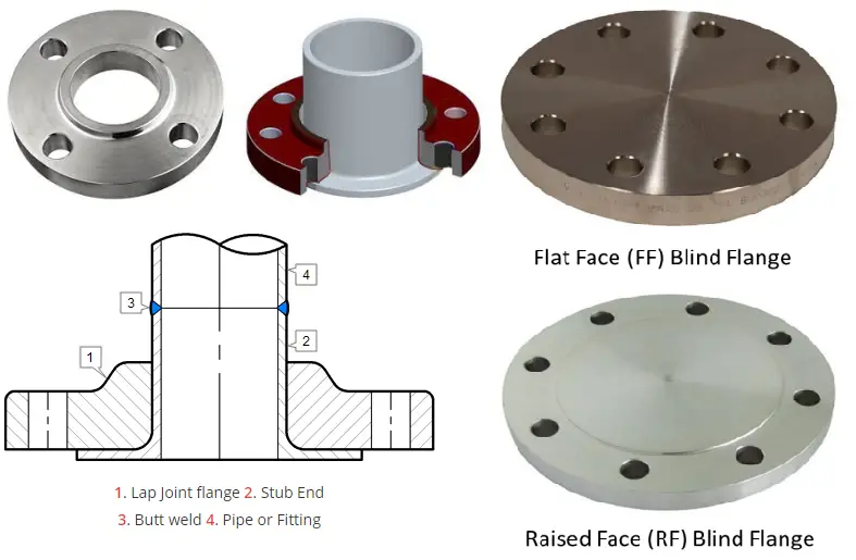
The main features of a lap joint flange are:
- Lap joint flanges are used as a combination with a lap joint stub.
- Lap joint flanges (Fig. 4) are a good alternative to costly flanges required for process design conditions. An ordinary steel flange behind the lap on alloy and stainless steel pipe without sacrificing internal corrosion protection can be used.
- In plastic piping systems, Lap joint flange is used.
- These flanges are comparable to slip-on flanges with respect to pressure-withstanding capability.
- The major disadvantage of lap joint flanges is that it has only about 10% of the fatigue life of welding neck flanges. That is why these flanges are not used where severe bending stresses exist.
- This type of joint avoids the necessity of accurate alignment of bolt holes since the flange is free to revolve on the pipe. So these flanges can be readily aligned with bolt holes of the mating flange.
- These types of flanges are also useful in cases where frequent dismantling for cleaning or inspection is required or when it is necessary to rotate the pipe by swiveling the flange.
Blind Flange
A blind flange is a solid flange and without the central hole used to seal or block off a section of pipe or a nozzle on equipment that is not used. Blind flanges are designed robustly as they have to withstand remarkable pressure stress. However, they don’t have to absorb thermal stresses as they are free to expand as attached at the end of the piping connection.
The weight of blind flanges (Fig. 4) is normally more than other flange types. They are frequently used during pressure testing of piping systems. Blind flanges can be of Flat or Raised Face type.
Socket Weld Flange
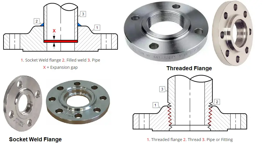
Socket weld flanges use only one fillet weld on the outer side of the flange. As per ASME B31.1, in a socket weld flange connection, the pipe is inserted in the socket at first until it reaches the flange bottom and then it is lifted by 1.6 mm and finally fillet welded. This 1.6 mm gap is kept to allow proper pipe positioning inside the flange socket after the weld solidification.
Socket Weld Flanges are suitable for small-size pipes (up to 2″) and are not recommended for severe services. They can be used for high-pressure piping that does not transfer highly corrosive fluids as fluid accumulation inside the gap will easily corrode the pipe.
From a strength point of view, socket weld flanges (Fig. 5) are comparable to slip-on flanges.
Threaded or Screwed Flange
Threaded flanges are joined to pipes by screwing the pipe and are used on piping systems that prohibit direct welding on the pipe. Usually, threaded flanges are used for Galvanized Piping. Industrial Threaded flanges are made in sizes up to 4 inches with various pressure ratings. Their use is mostly limited to small pipe sizes carrying low-pressure temperature fluids.
Threaded flanges (Fig. 5) are frequently used in areas containing explosives. Cutting thread on very thin pipes is difficult, threaded flanges are used on relatively thicker pipes. The main features of screwed flanges are:
- The attachment process or joining method is quick.
- The threads are prone to leakage under cyclic loading, hence not recommended for cyclic services.
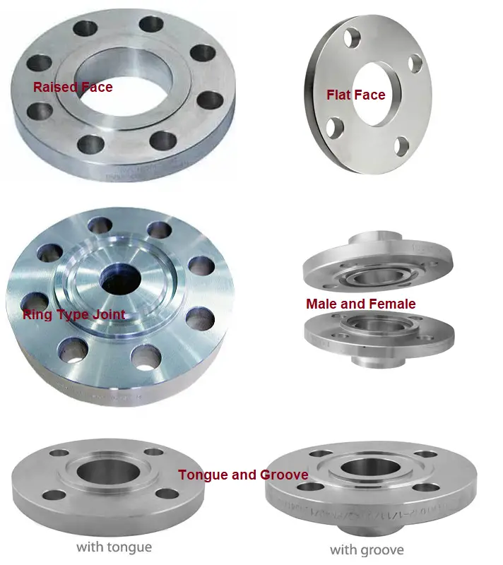
Pipe Flange Types Based on Flange Facing
Based on Flange Facings, the flanges are classified as
- Raised Face Flanges
- Flat Face Flanges
- Ring Type Joint Flanges
- Tongue and Groove
- Male and Female
Types of Pipe Flanges Based on Pressure-Temperature Rating
Based on pressure-temperature rating flanges are of the following types:
- 150#
- 300#
- 400#
- 600#
- 900#
- 1500#
- 2500#
With an increase in pressure rating the flange dimensions, strength, and load-carrying capacity increase. Click here to know more about the pressure-temperature rating and flange rating.
Flange Types based on Governing Design Code
Based on governing design code piping flanges can be grouped into the following classes
- ASME/ANSI Flanges (ASME B 16.1, ASME B 16.5, ASME B 16.42, ASME B 16.47)
- BS Flanges (BS 10, BS 1560)
- API Flanges (API 6A, API 17D)
- DIN flanges
- Custom made flanges, etc
Additionally, based on the pipe flange material of construction they can be classified as
- Metallic Flanges
- Carbon Steel Flanges
- Alloy Steel Flanges
- SS/DSS Flanges
- Cast Iron Flanges
- Ductile Iron Flanges
- Non-Metallic Flanges (FRP/GRP/GRE Flanges)
Few more hand-picked flange related articles for you
Methods for Checking Flange Leakage
Flange Insulating Gasket Kits for Industrial Application
Guidelines for Selection of Various Types of Flanges
Flange Bolt tightening Procedure/Bolt Tightening Steps