Piping insulation is a crucial aspect of any industrial, commercial, or residential piping system. It serves multiple purposes, from conserving energy and reducing heat loss to preventing condensation and protecting pipes from extreme temperatures. The choice of insulation material is critical and depends on several factors, including the operating temperature of the pipes, environmental conditions, and specific industry requirements. In this article, we’ll try to provide in-depth knowledge about all aspects of piping insulation.
Pipe Insulations are materials or combinations of materials wrapped around the pipe which retard the flow of heat energy. Pipe insulation reduces energy losses to a great extent and thereby reduces the energy cost. Piping shall be insulated as per the insulation class, operating temperature, and insulation thickness stated in the P&ID.
Functions of Pipe Insulation | Why is Piping Insulation Important?
A piping insulation system serves three principal purposes:
- The significant reduction in heat transfer of thermal energy to and from the surface of the piping system (Heat Conservation). So, piping insulation conserves energy and improves system efficiency.
- The prevention of moisture formation and collection on the surface of the piping system due to condensation on cold surfaces (Cold Insulation).
- The prevention of potentially injurious personnel contact with the surface of the exposed piping system (Personal Protection).
However, there are various other benefits of piping insulation as listed below
- Piping insulation facilitates temperature control of the process.
- Prevent vapor flow and water condensation on cold surfaces.
- Increase the operating efficiency of heating/cooling, power, and process systems.
- Reduce major damages in the piping during fire or accidents.
- Prevent pollutant emissions to the atmosphere to a great extent.
- In colder climates, insulation prevents water in pipes from freezing, which can cause bursting and significant damage.
- Sometimes Steam traced/Electric traced insulation, Regeneration insulation, jacketing, etc. are used as per process/licensor requirements.
- Some insulation materials can dampen sound, reducing noise levels in a facility.
- Fireproofing, fire protection, and acoustic insulation (to control noise and absorb vibration) are provided based on project specifications/ ITB requirements.
Pipe Insulation Types
Piping insulation can be classified based on various parameters like
- Based on the Pipe Insulation Function
- Hot Insulation
- Cold Insulation
- Personal Protection Insulation
- Acoustic Insulation
- Based on Insulation Material Types
- Fibrous Insulation
- Cellular Insulation
- Granular Insulation
Piping Insulation Types Based on the Function of Pipe Insulation
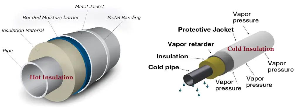
Hot Insulation
Hot insulation is applied on the hot surfaces of the piping system to prevent the energy flow from flowing fluid. So, the main aim of hot piping insulation is heat conservation. Mineral Wool, Glass Wool, Calcium Silicate, etc. are normally used as Hot insulating material. Hot Piping Insulation is typically applied for process temperatures above 60°C.
Cold Insulation
Cold Insulation is the insulation used on cold surfaces of the piping system to avoid heat gain from outside (Cold Conservation) or to avoid Condensation. Polyurethane Foam, Expanded Perlite Foam, Expanded Polystyrene Foam, etc. are the widely used cold insulating materials.
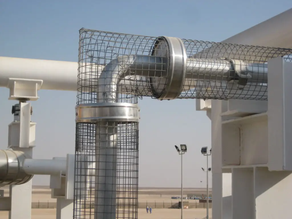
Personal Protection Insulation
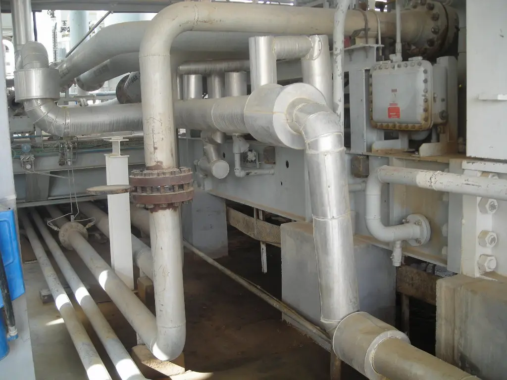
Personal Protection insulation is provided to avoid personal heat injury. All exposed piping surfaces that exceed 60 degrees C are provided with personal protection insulation. The areas that are not accessible by construction or operating personnel can be left exposed. An open mesh metal guard (Fig. 2), mineral wool, etc. are used as personal protection insulation material.
The criteria for personal protection is that the exposed surfaces located within 600 mm horizontally or 2100 mm vertically of a normal access, walkway, or work area are to be insulated.
Acoustic insulation
Acoustic Insulation is provided for all piping that is considered a potential sound source. The main purpose is to reduce the noise (vibration) to an acceptable limit. The minimum thickness for acoustic insulation is normally 75 mm. Acoustic Foam, fiberglass, polyester/polyurethane foams, rock wool, Mass Loaded Vinyl, etc. are used as Acoustic Insulating material.
Piping Insulation Types based on insulation material types
Fibrous Insulation
Fibrous insulation consists of small diameter fibers which finely divide the air space. The fibers may be perpendicular or parallel to the surface being insulated, and they may or may not be bonded together.
Common fibers used in piping insulation are Silica, slag wool, rock wool, and alumina-silica. Among these, Glass fiber and Mineral Wool are the two most widely used piping insulations of this type. Their fibers are normally bonded with organic binders for structural integrity.
Cellular Insulation
Cellular pipe insulation material comprises small individual cells separated from each other. Common cellular materials used as pipe insulation are glass or foamed plastics such as cellular glass, phenolic foam, or nitrile rubber.
Granular Insulation
Small nodules containing voids or hollow spaces constitute granular insulation. As gas can be transferred between the individual spaces, It is not considered a true cellular material. This type is manufactured as loose or pourable material or combined with a binder and fibers. Sometimes they undergo a chemical reaction to form rigid insulation. Calcium silicate and vermiculite are examples of these types of insulations.
Pipe Insulation Material
- Low-temperature insulation is frequently made of expanded cellular plastic or foam rubber material.
- Moderate temperature insulations are made from grass fiber products.
- High-temperature insulation is made of preformed cementations or refractory materials or blankets made from ceramic fibers.
- Insulation and accessory materials have to be 100% asbestos-free.
- Normally mineral fiber, cellular glass, ceramic fiber, glass fiber, polyisocyanurate, polyurethane foam, Rockwool, Glass Wool, Expanded Perlite, Flexible Elastomeric Foam (FEF), Flexible aerogel blanket, Calcium magnesium silicate wool (CMS), Alkaline earth silicate wool (AES), Calcium Silicate, etc. are used as pipe insulation material.
The following table provides details of some commonly used insulation materials:
| Pipe Insulation Material | Density (kg/m3) | Temperature Limitation |
| Mineral Glass Fibre | up to 535°C | |
| Mineral Wool | 140 | up to 700°C |
| Rock Wool | 140 | up to 550°C |
| Glass Wool | 80 | up to 450°C |
| Calcium Silicate | 200-280 | up to 815°C |
| Expanded Perlite | 192 | up to 550°C |
| Expanded Silica | up to 535°C | |
| Refractory Fiber | 150 | up to 1750°C |
| Polyurethane Foam | 40 | from -150°C to 110°C |
| Polyisocyanurate | 40-64 | from -150°C to 125°C |
| Cellular Glass | 147 | up to 350°C |
| Ceramic Fibre | 250 | up to 760°C |
Some Typical Pipe Insulation materials are described below:
- Fiberglass Insulation: Fiberglass is one of the most common and widely used insulation materials. It is made from fine glass fibers and is available in pre-formed sections, blankets, or wraps.
- Mineral Wool (Rockwool) Insulation: Mineral wool, also known as rockwool or slag wool, is made from molten rock or industrial waste products spun into fibers. It is known for its excellent fire-resistant properties. It can withstand temperatures up to 700°C.
- Cellular Glass Insulation: Cellular glass insulation is made from crushed glass that is heat-treated to create a closed-cell structure. This material is highly resistant to moisture and chemicals. ASTM C552 gives the Standard Specification for Cellular Glass Thermal Insulation.
- Foam Glass Insulation: Foam glass is another form of cellular glass insulation but is produced using a different process that results in a lighter, more flexible material.
- Polyurethane Foam (PUR) Insulation: Polyurethane foam is a versatile insulation material known for its low thermal conductivity and high resistance to water. It is available as spray foam or pre-formed sections. It can operate effectively between -150°C to 110°C.
- Elastomeric Foam Insulation: Elastomeric foam insulation is a flexible, closed-cell material made from synthetic rubber. It is particularly effective in preventing condensation on cold pipes.
- Calcium Silicate Insulation: Calcium silicate is a high-temperature insulation material made from lime and silica. It is widely used in industrial applications due to its durability and thermal stability. It is effective up to 815°C. ASTM C533 provides the Standard Specification for Calcium Silicate Block and Pipe Thermal Insulation.
- Aerogel Insulation: Aerogel is a cutting-edge insulation material known for its ultra-low thermal conductivity. It is one of the lightest solid materials available and offers superior insulation performance. Its effective temperature range is from -268°C to 650°C.
Piping Insulation System
The main part of the Piping insulation system is the insulating material. Other elements that constitute the pipe insulation system are
- Protective Coating
- Vapor Barrier
- The cladding of the metallic sheet.
- Spacers to enable cladding to retain its shape.
- Packing to fill the cavities or voids, if any.
Pipe Insulation Forms
Insulations are manufactured in a variety of forms to suit specific applications and functions. The installation method is decided by the combined insulation form and type of insulation. The most widely used insulation forms are:
- Rigid boards, sheets, blocks, and pre-formed shapes: Cellular, granular, and fibrous insulations are produced in these forms.
- Flexible sheets and pre-formed shapes: Cellular and fibrous insulations are produced in these forms.
- Flexible blankets: Fibrous insulations are produced in flexible blankets.
- Cement (insulating and finishing): Produced from fibrous and granular insulations and cement, they may be of the hydraulic setting or airdrying type.
- Foams: Poured or froth foam used to fill irregular areas and voids. The spray is used for flat surfaces.
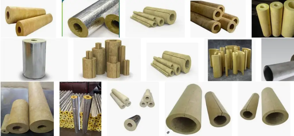
Normally, Rock and Glasswool are pre-formed in two halves; Polyisocyanurate, Polyurethane, and Cellular Glass are supplied in preformed cylindrical shapes to slit in half lengthwise, and ceramic fiber is supplied in blanket strips.
Piping Insulation Standards
The following codes and standards provide guidelines for industrial piping insulation:
- ASTM C533, ASTM C547, ASTM C552, ASTM C591, ASTM C592, ASTM C610, ASTM C612, ASTM C795, ASTM C892, ASTM C165, ASTM C240, ASTM C302, ASTM C303, ASTM C335, ASTM C356, ASTM C390, ASTM C446, ASTM C680.
- BS 1902 Part 6, BS 4370 Part 2, BS 5608
- IS 11239, IS 12436, IS 9428, IS 8183, IS 4671, IS 3690
- ISO 15665- Acoustic Piping Insulation
- EN ISO 23993
Factors Affecting Piping Insulation Performance
For any specific application, the main factors that impact the relative performance of various pipe insulation are:
- Pipe Insulation thickness
- Thermal conductivity (“k” or “λ” value) of Insulation Material
- Surface emissivity value or “ε” value
- Water-vapor resistance (“μ” value)
- Density of the insulating material
- Level of moisture content
- Opening of Joints
Piping Insulation Thickness Calculation
Piping Insulation System Design Considerations
Some important design considerations related to piping insulation (May vary from project to project):
- All insulating materials need to be free from harmful products affecting human health and the environment. To be more specific, the piping insulation material needs to be free from known carcinogens, asbestos, Chlorofluorocarbon (CFCs), Hydrochlorofluorocarbon (HCFCs), heavy metals such as lead or cadmium, and PCBs.
- Insulation thickness is determined based on pipe size, normal operating temperature, temperature controlling requirement (extent of heat loss/gain), etc. At a minimum 25 mm pipe insulation thickness is to be used.
- If the insulation thickness is more than 75 mm then insulation is provided in two or more layers (multi-layer).
- Insulation shall not be applied until hydrostatic/ pneumatic testing is performed.
- Insulation up to 12-inch NPS pipe shall be held with SS-304 tie wire and for > 12-inch NPS SS-304 bands are used.
- All flanges will be insulated other than hydrogen service or high health hazard material services.
- All valves other than control valves and relief valves shall be insulated.
- Certain piping items like vents, steam-out and snuffing steam systems, flare and blow-down systems; Piping supports; Steam Traps; Expansion joints, hinged joints and hose assemblies; Instrument connections; Sight flow indicators, etc. are usually not insulated.
- Each pipe must be insulated separately except where the second pipe is for heat tracing.
Piping Insulation Thickness Chart
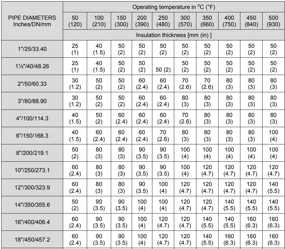
A piping insulation thickness chart is a reference chart for piping engineers, designers, and insulation installers when determining the appropriate insulation thickness for various piping systems. The insulation charts are made by economic pipe insulation thickness calculation and presented in a tabular format for easy reference. The piping insulation thickness chart typically includes information on pipe insulation thickness corresponding to the operating temperature range and pipe sizes. A separate table for each type of piping insulation (Hot, cold, or personal protection) is prepared.
The following Image (Fig. 6) shows a typical pipe insulation thickness chart for Heat Conservation Insulation. Note that the image only provides a sample reference for the piping insulation thickness chart, for actual values you must refer to your project-specific data.
Choosing the right type of piping insulation depends on various factors, including the temperature range of the system, environmental conditions, and specific industry requirements. Proper installation and maintenance of insulation are also crucial to achieving the desired performance.
Frequently Asked Questions: Piping Insulation
How does pipe insulation work?
Pipe insulation works by creating a barrier that reduces the transfer of heat between the pipe and its surroundings. This barrier minimizes heat loss in hot pipes and prevents heat gain in cold pipes. Additionally, insulation prevents condensation on cold pipes and provides a layer of protection against extreme temperatures, which can prevent freezing or overheating.
How thick should pipe insulation be?
The thickness of pipe insulation depends on several factors, including the temperature of the fluid inside the pipe, the ambient temperature, and the type of insulation material used. For most applications, insulation thickness ranges from 1/2 inch to 2 inches. Higher temperatures or more extreme environments may require thicker insulation for optimal performance. The thickness of piping insulation is calculated during the detailed design phase of a project as explained here.
How do I select the right pipe insulation?
Selecting the right pipe insulation involves considering several factors:
- Temperature Range: Ensure the insulation can handle the operating temperature of your system.
- Moisture Resistance: If the pipes are exposed to moisture or humid environments, choose insulation with good moisture resistance.
- Fire Resistance: For high-temperature or fire-rated systems, select a material with excellent fire resistance.
- Cost and Availability: Consider the cost and availability of the insulation material.
- Specific Application: Different environments and applications may require specialized insulation types, such as cryogenic systems or underground piping.
What is the best insulation material for pipes?
The best insulation material depends on the specific application. Fiberglass is popular for general use due to its affordability and effectiveness. Mineral wool is preferred for high-temperature applications, while elastomeric foam is ideal for preventing condensation on cold pipes. For extreme environments, materials like cellular glass or aerogel may be the best options.
How do I install pipe insulation?
Installing pipe insulation typically involves the following steps:
- Measure and Cut: Measure the length and diameter of the pipe and cut the insulation material to fit.
- Wrap or Slip On: Depending on the material, either wrap the insulation around the pipe or slip pre-formed sections over it.
- Seal the Joints: Use appropriate adhesive, tape, or fasteners to seal any joints or seams to prevent heat loss or moisture ingress.
- Protect and Finish: In some cases, especially outdoors or in high-traffic areas, you’ll need to apply a protective jacket or coating over the insulation.
Can pipe insulation be used on hot pipes?
Yes, pipe insulation is commonly used on hot pipes to reduce heat loss, improve energy efficiency, and prevent burns from accidental contact. Materials like fiberglass, mineral wool, and calcium silicate are particularly suited for insulating hot pipes.
Can pipe insulation be used on cold water pipes?
Yes, pipe insulation is effective on cold water pipes. It helps prevent condensation, which can lead to mold, corrosion, and water damage. Elastomeric foam and fiberglass are often used for cold water pipes due to their moisture-resistant properties.
What is the most effective pipe insulation?
The most effective pipe insulation in terms of thermal performance is aerogel insulation. It has an exceptionally low thermal conductivity, meaning it provides superior insulation with thinner layers compared to other materials. However, aerogel is also more expensive and may be overkill for standard applications.