All Piping stress engineers who use Intergraph’s Caesar II software must be aware that there is an inbuilt API 610 module for API centrifugal pump nozzle load checking. By the use of this module, you can directly check if the pump nozzle loads are within acceptable limits provided by the API 610 code. Searching the code for allowable load or asking the vendor for the nozzle limiting force and moments are not required.
The method of using the API 610 module is fairly simple. But before you start using the module you have to perform static analysis following conventional methods. In this video tutorial, the API 610 module is explained clearly.
Types of Pressure-Relieving Devices for Protection from Overpressure
Pressure Relieving Devices or PRDs are devices used in chemical, petrochemical, and power industries to prevent equipment from over-pressurization. As per the design requirements, these pressure-relieving devices function to relieve excess pressure generated in the system. PRDs are widely used for gas, steam, vapor, or liquid services. To protect operating personnel and equipment from unforeseen adverse impacts, pressure-relieving devices play an important role.
Pressure-relieving devices protect a vessel or item of equipment against overpressure and not against failure due to high temperature when exposed to fire, or failure due to corrosion. Safety in connection with such failures must be considered independently.
Types of Pressure-Relieving Devices
Various types of relieving devices used in process plants are as follows:
In the following paragraphs, we will learn about these pressure-relieving devices in brief
A. Pressure Relief Valve:
A pressure relief device actuated by inlet static pressure and designed to reclose and prevent the further flow of fluid after normal conditions have been restored.
The pressure relief valve is a generic term applied to relief valves, safety valves, safety relief valves, or pilot-operated pressure relief valves. A short Description of these valves is given at the end of this article.
B. Non-Reclosing Pressure Relief Device:
A pressure relief device designed to remain open after operation.
C. Safety Valve:
A safety valve is a pressure relief valve characterized by rapid opening or pop action. It is used for gas or vapor service.
D. Relief Valve:
A relief valve is a pressure relief valve, which opens in proportion to the increase in pressure over the opening pressure. Relief valves are generally used for liquids. In this type of valve, at the set pressure, the disk rises slightly from the seat without popping and permits a small amount of fluid to pass. As the pressure in the vessel increases, the disk is further raised; thus an additional area is available so as to allow an increased flow of fluid.
E. Safety Relief Valve:
A safety relief valve is a pressure relief valve that can be used in either vapor or liquid service. For vapor service, it is adjusted to give a “pop” action, for liquid service it is adjusted for gradual opening.
F. Pilot Operated Pressure Relief Valve:
This is a pressure relief valve in which the major relieving device is combined with and is controlled by a self-actuated auxiliary pressure relief valve (pilot). The use of pilot-operated pressure relief valves may be limited by the fluid characteristics (fouling, viscosity, presence of solids, corrosiveness) or by the operating temperature. The manufacturer should then be consulted.
G. Pilot-Assisted Pressure Relief Valve:
This pressure relief valve is a standard pressure relief valve (spring-loaded) fitted with an additional spring-diaphragm actuator to which a pneumatic signal is fed from a pressure-sensing pilot. The arrangement connecting the actuator to the spindle is such that the valve is still capable of operating as a standard safety valve in the event of pilot or actuator failure. The pressure relief valve will then open at 105 % of the set pressure as the valve spring set pressure is normally adjusted to 5 % higher than the pilot set pressure.
H. Power-Actuated Pressure Relieving Valve:
Movements to open or close are fully controlled by an external source of power (electricity, air, steam, or hydraulic). If the powder-actuated pressure-relieving valve is also positioned in response to other control signals, the control impulse to prevent over-pressure shall be responsive only to pressure and shall override any other control function.
It has to be noted that the power-actuated pressure relieving valve cannot be considered a safety device, since, unlike the others, it relies on an external source of power.
I. Rupture Disk Device:
A non-reclosing differential pressure relief device actuated by inlet static pressure and designed to function by the bursting of a pressure-containing disk. A rupture disk device includes the rupture disk or sensitive element and the rupture disk holder. Rupture disk devices are used either alone or in conjunction with a pressure relief valve. The application of rupture disks alone is limited by the fact that when the disk ruptures the entire contents of the system may be lost. They may, however, be installed in parallel with a pressure relief valve to provide the additional capacity; in this case, the relief valve is set at a lower pressure to limit rupture disk bursting to major disasters.
Rupture disks
are pressure differential devices and the relieving capacity is therefore
affected by the sizes and lengths of the inlet and outlet pipework.
J. Breaking Pin Devices and Spring-Loaded Non-Reclosing Pressure Relief Devices:
A breaking pin device is a non-reclosing pressure relief device actuated by inlet static pressure and designed to function by the breakage of a load-carrying section of a pin that supports a pressure-containing member. A breaking pin device includes the breaking pin or load-carrying element and the breaking pin housing. Breaking pin devices shall not be used as single devices but only in combination between the pressure relief valve and the vessel.
A spring-loaded non-reclosing pressure relief device is a pressure-actuated by means which permit the spring-loaded portion of the device to open at the specified set pressure and remain open until manually reset. It may be used provided the design of the spring-loaded non-reclosing device is such that if the actuating means fail, the device will achieve full opening at or below its set pressure. Such a device may not be used in combination with any other pressure relief device.
K. Explosion Hatch:
A hinged metal cover is placed over an opening in a vessel. The hatch consists of a hinged metal cover placed over an opening. It is used for vessels operating near atmospheric pressure and when the risk of explosion exists. Explosion hatches are not recommended for use at higher pressures, since the weight of the hatch will be excessive and this may prevent quick opening.
L. Liquid Seal:
Liquid seals can be used instead of pressure relief valves for set pressures below 10-15 psig, where relief valves are not considered reliable. Typical examples are the seal leg of a flare and liquid seals used in MEK units to protect the filters. The “U-tube” may be filled with water, mercury, or other liquid. Freezing of the sealing liquid shall be avoided by steam tracing or heating. Provisions for make-up and draining of the filling liquid should be made.
M. Vacuum Relieving Devices:
A vacuum can be the normal operating conditions of a vessel (e.g. Vacuum Towers) or an occasional event for vessels normally operating under pressure. This can happen due to internal vapor or steam condensation, pumping out, gravity transfer of liquids, loss of heating and temperature changes, etc.
In the first case, the vessel is designed to withstand a full vacuum. In the second case, the designer can choose between specifying the vessel for full vacuum or providing a vacuum relief device (valve or liquid seal) that permits the entrance of air, inert gas, or fuel gas, etc., to prevent vacuum conditions.
It is important
to specify the actual temperature coincident with occasional vacuum conditions.
This temperature may be appreciably lower than the normal operating
temperature. Based on the pressure/temperature level when the occasional
condition occurs, vessel specialists will check the wall thickness required, which
may not have to be increased due to the lower temperature coincident with
vacuum conditions.
N. “O Ring” Seat Seal or Stellited Pressure Relief Valve:
Pressure relief valves may leak when the operating pressure is above 90 % of the valve set pressure. It is possible to enhance the tightness of a spring-loaded pressure relief valve for max operating pressure up to 92 % of set pressure (above 92 % consider pilot-operated pressure relief valves), either with :
an “O ring” seat seal; the compatibility of this seal with the product has to be carefully investigated,
a stellited pressure relief valve.
Short descriptions of Safety valves and safety Relief Valves are given here.
Safety Valves and Safety-Relief Valves:
These are pressure-relieving devices for gases or vapors which have been specifically designed to give full opening with little over-pressure. The kinetic energy of relieving gas or vapor creates a pop action that opens the disk rapidly, reaching the full lift before maximum overpressure. There are two basic types of safety valves: conventional and balanced valves.
Conventional Type Relief Valve
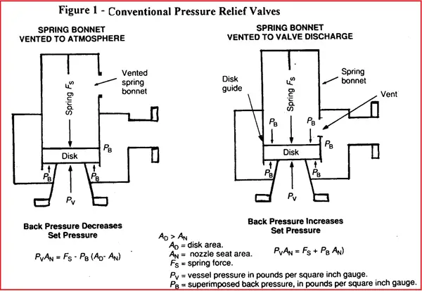
Conventional
relieving valves are shown schematically in Fig. 1. The following two
situations are possible :
If the bonnet is vented to the atmosphere, the backpressure acts with the vessel pressure against the spring force.
If the spring bonnet is vented to the valve discharge rather than to the atmosphere, the backpressure acts with the spring force.
If the superimposed backpressure were constant, (no matter what its value), it could be taken into account in adjusting the spring loading so that the relief valve would open at the required set pressure. In practice, however, the superimposed back pressure is generally not constant and varies between a minimum, which corresponds to the flow of purge gas alone in the flare system (no valve discharging), and a maximum which corresponds to the design flow of the flare system.
Fig. 1: Conventional Pressure Relief Valve
For a conventional valve of type B, the ‘spring’ set pressure is equal to the design pressure minus superimposed back pressure; therefore the valve will open above the vessel design pressure if the superimposed back pressure is higher than expected, and will open below design pressure if the superimposed back pressure is lower than expected.
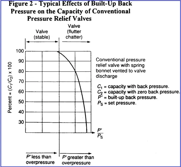
In order to avoid opening the valve at pressures too different from the required set value (as a result of variable superimposed back pressure), the first step is to only accept the use of conventional relieving valves when superimposed back pressure varies over a range not exceeding 10% of set pressure (gauge). However, this is not always sufficient because the flow performance after opening must also be examined. When the valve is open, the built-up backpressure tends to unbalance the equilibrium between spring force and vessel pressure. For a conventional valve of type B, this may result in a reduction of valve opening and a rapid fall of capacity (see Fig. 2). Therefore conventional valves, even when acceptable from the point of view of superimposed backpressure, must be checked with regard to built-up backpressure. The designer must check that the difference between the maximum value of backpressure and the minimum value of superimposed back pressure does not exceed 10% of the set pressure (gauge).
Fig. 2: Back Pressure vs capacity of Conventional Pressure relief Valve
Balanced Type Pressure Relief Valve
Balanced safety
relief valves are those in which the back pressure has little influence on the
performance characteristics.
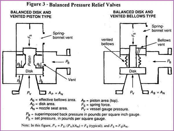
Piston type and
Bellows type are available, the latter being more widely used (See Fig. 3).
Bellows Type Pressure Relief Valve-
The effective bellows cross-sectional area is equal to the nozzle seat area; disk areas extending beyond the bellows and beyond the seating area are equal and forces developed over those areas cancel each other.
The area under the bellows is kept under constant pressure by venting the bellows to a source of constant pressure, which is often the atmosphere unless the fluid that would be vented in case of bellows failure is dangerous; in that case, the vent should be discharged to a safe location, provided that its pressure is constant. Bellows valves have limited allowable set and outlet pressures.
If the maximum set or backpressure allowed for a single orifice appears too low, use a combination of smaller valves having an aggregate area equal to the valve in question. The use of smaller valves will permit higher set or back pressures.
Piston Type Pressure Relief valve-
In the piston type, of which several variations are manufactured, the piston guide is vented so that the back pressure on opposing faces of the valve disk cancels itself, and the top face of the piston, which has the same area as the nozzle seat area, is kept at atmospheric pressure by venting the bonnet.
Since gases may
leak past the piston to the bonnet, the bonnet of piston-type valves must be
vented in a safe manner.
Note that the
vent on the valve bonnet should not be piped back into the flare header as its
performance will then be the same as a conventional valve.
With balanced-type relieving devices, not subject to the limitations of back pressure set for conventional devices, the back pressure (superimposed and built-up) can be allowed to rise, permitting a reduction in size and cost of the relief header.
However, even when using balanced-type valves, when back pressure reaches 30% of the set pressure, the capacity of the valve for vapors and gases starts to fall below the theoretical capacity. With liquids, the capacity reduction starts at 15% of the set pressure. The fall-off in valve capacity depends also on overpressure, type, and make of valve used
For back pressures higher than this limit, valve size becomes progressively larger for the same flow, even if critical flow conditions are maintained. For back pressures higher than 50% of the set pressure, the valve manufacturer must always be consulted for valve sizing. In general, although there would be an incentive in increasing back pressure with balanced-type valves in order to reduce the size and cost of relief headers, values exceeding 30-35% of set pressure (gauge) should not be used without checking with an instrument specialist.
Pipeline Construction means laying the pipes to serve their intended purposes. There are two kinds of pipelines: Liquid and Gaseous. The construction of both pipelines is similar. The construction of large-scale cross-country pipelines involves a multitude of activities.
The construction of a pipeline can be compared with a moving assembly line. A large pipeline construction project is usually broken into manageable lengths called “spreads,”. Each spread is attacked at a time utilizing highly specialized and qualified workgroups. Each spread consists of various crews having their own responsibilities. As one crew finishes its work, the next crew takes its position to complete its piece of the pipeline construction process.
Pipeline construction steps usually take years to complete. Many surveys, studies, and plans are required to be completed before the construction of the pipeline starts. A comprehensive plan addressing the societal, developmental, environmental, and safety considerations are prepared to build the pipeline.
Pipeline Construction Steps
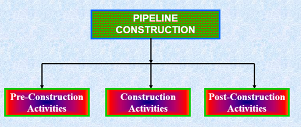
The construction of pipelines is a multi-step process. Many months prior to the actual pipeline construction phase, planning and surveys are conducted. Pipeline Construction steps can broadly be classified into the following three categories:
Pipeline Pre-Construction Activities
Pipeline Construction activities and
Pipeline Post-Construction Activities
Fig. 1: Pipeline Construction Activities
Pipeline Pre-Construction Activities
Pipeline pre-construction activities shall include the following:
Reconnaissance Survey
Detailed Engineering Survey
Permits and Clearance
Cadastral Survey
Acquisition of Right of Way
(ROW)
Acquisition of Land for
Repeater Stations and Block Valves
Approval of QA/QC procedure
Reconnaissance Survey
The main objectives of a Reconnaissance survey in pipeline construction are
To establish the pipeline route
To avoid populated areas, forest, and mining areas
To keep the number of crossings to a minimum
To ensure easy approachability to the ROW
The utilization of existing ROW if any.
The reconnaissance survey is carried out by the following activities:
Visual inspection of all welds shall be carried out by a qualified welding inspector having minimum qualification of Level – II certification.
All joints at the following locations shall be radiographed.
Initial 1 km.
At cased road/rail, submerged crossings,
Tie-ins (including golden tie-ins)
Marshy areas.
Valves and insulating couplings
20% of balance mainline joints(100% here)
Field Joint Coating
250 mm on either side of the pipe is left uncoated in the coating yard to facilitate welding.
The width of the sleeve shall depend upon the cut-back length provided in the yard-coated pipe.
Heat-shrinkable sleeves are used for coating welded joints.
Joint Coating procedure
The pipe surface is sandblasted to SA-21/2 specification.
The sandblasted area is heated up to 600C and the epoxy primary is applied on the surface.
The sleeve is wrapped around and then shrunk on the joint using a propane/ LPG torch.
Air bubbles trapped are removed using hand rollers.
The integrity of the joint coating is tested by conducting a peel test.
Lowering of Pipeline in the trenches for Pipeline construction
The excavated trench should be free from excess earth, rock, hard clods, and other debris.
The coating of the pipe string shall be checked for damages by using a holiday detector.
Repair of coating damages.
Sand padding and rock shield are provided in rocky areas before lowering.
Backfilling of Pipeline
Backfilling shall be done immediately after lowering.
Backfilling shall be done with earth free of hard lumps, boulders, rock, etc.
Sand padding over the pipe shall be provided in rocky areas.
Slope breakers shall be provided in steep gradients to avoid the washout of the trench.
Pipeline Construction Tie-ins
Situations in the mainline such as rail/ road/ river crossings etc. may cause a break in the continuity of mainline laying operation and are normally bypassed by the mainline laying crew.
The process of connecting the unconnected sections of the pipeline is defined as a tie-in operation.
Crossings in Pipeline construction Route
Type of Crossings:
Open cut :Roads, cart tracks, and minor watercourses.
Cased :Railways, National Highways, and State Highways
Submerged crossings :Major rivers
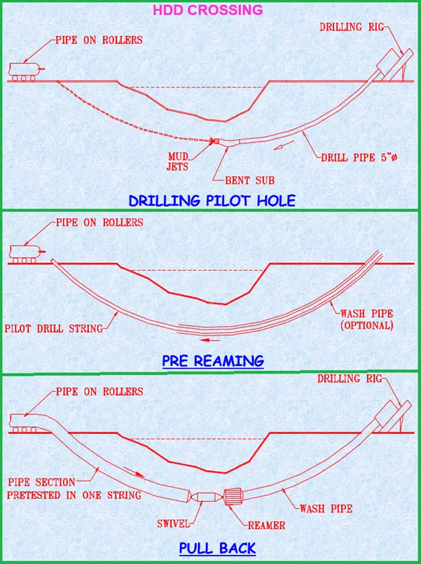
HDD crossings :Perennial rivers and canals
HDD CROSSING:
Fig. 2: HDD Crossing
Hydrostatic Testing of Pipeline during Pipeline construction
Objectives for Hydrotesting
To establish that the pipeline has the required strength for which it has been designed.
To demonstrate leak tightness
of the pipeline.
Parameters for choosing test sections
Availability of water
Suitable place for disposal
Ground profile
Logistics
Pipeline Hydro-Test procedure:
Air cleaning the pipeline to clear all debris and muck
Gauging
Water filling with corrosion
inhibitor
Thermal stabilization
Pressurization
Evaluation and acceptance
Pipeline Valve Installation
Block valves are either Hand operated or Motor operated.
Mainline isolation valves are provided at an approximate interval of 25 to 35 km. depending upon the size of the line.
Isolation valves are provided on either side of major rivers.
Tapings for the pig signaler and pressure transmitters are provided at the valve locations for monitoring the pressure, temperature, and moment of the pig.
Final clean-up, Restoration, and Installation of Markers
After construction, ROW is leveled and restored to the entire satisfaction of the landowners/ authorities.
All drains, utility lines, and water lines damaged during construction are restored to their original position.
Pipeline markers such as kilometer posts, turning points/ direction markers, warning signs, and boundary pillars are provided.
ROW is notified for closure.
Payment of crop compensation.
Documentation of Pipeline Construction Activities
All pipeline construction activities must be documented for future reference purposes. The following should be maintained
Centrifugal compressor surge is a characteristic behavior of the compressor that occurs in situations when inlet flow is reduced and the compressor head developed is so low that it can not overcome the pressure at the compressor discharge. During a centrifugal compressor surge situation, the compressor outlet pressure (and energy) reduce dramatically which causes a flow reversal within the compressor.
The surge in a centrifugal compressor is considered to be a very dangerous and detrimental phenomenon as it results in compressor vibration that results in the failure of the compressor parts. Compressor surge normally occurs in centrifugal and axial compressors. Compressor surge is a cyclic event and this results in high strain on compressor bearings, seals, and the impeller. The resulting severe vibration can lead to damage to the motor compressor coupling and the baseplate.
Ask a chemical or mechanical engineer, what a compressor surge does, and he would shudder merely thinking of the consequences. The centrifugal compressor is the heart of any oil & gas facility and for the last 100 years has been subjected to scrutiny as to what is the perfect control mechanism.
The Surge in a centrifugal compressor can be simply defined as a situation where a flow reversal from the discharge side back into the compressor casing occurs causing mechanical damage
What Causes Compressor Surge?
Various reasons could contribute to a centrifugal compressor surge. The reasons are multitude ranging from a
Driver failure,
Misdistribution of load in the compressor
Power failure,
Restrictions in the inlet and outlet of the system
The consequences of a compressor surge are more mechanical in nature whereby ball bearings, seals, thrust bearings, collar shafts, impellers, etc wear out and sometimes depending on how powerful are the compressor surge forces, cause fractures to the machinery parts due to excessive vibrations. Other bad consequences of the compressor surge are:
The flow reversal could cause process-related problems leading to plant shutdown.
As the hot compressed gas is returning at the inlet, it will result in an increase in the compressor inlet temperature.
As long as this surge will prevail, a large dynamic force will act on the compressor impeller and blade.
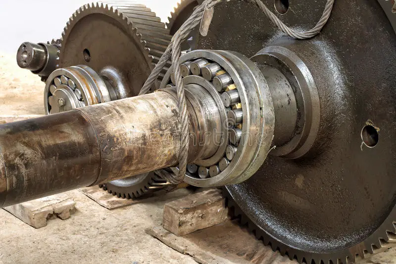
Here is an image, that shows the bearings being dislodged from their containment. The effects of the compressor surge are also contagious and due to excessive shaft vibrations, the gearbox connected between the compressor and the driver is also not spared at the bearings and gear teeth.
The power of a compressor surge is also proportional to the capacities (flow, power, pressure ratio) and even in the case of small turbo compressors, the gear teeth wear out when the impeller rotates in the opposite direction during a surge.
The bottom line is: Always avoid a surge in compressors and other rotating equipment.
Compressor Surge Control
Compressor Surge Control using Anti-surge Valve (ASV)-Cold Gas Recycle
The chief protecting agent of a centrifugal compressor is the anti-surge line/valve that recycles cold gas from the discharge side cooler back to the suction scrubber to keep the operating point away from the surge line.
Compressor Surge Control: Hot Gas Recycle Valve
Although the anti-surge valve (ASV) is the chief protector, in brownfield projects, often the ASV becomes inadequate to deal with a compressor surge due to the addition of new compressors in parallel or series (e.g., booster compressors), change of plant piping or change of vapor composition. In these situations, a necessity arises to recycle more flow for which an additional ASV with quick opening characteristics is installed in parallel to the first ASV. When such solutions still fail to stop a compressor surge event from occurring, a hot gas recycles (a.k.a HGV) is used as a last resort. The second image below shows a gas compressor with hot gas recycles whose operating point moved away from the compressor surge line during an emergency shutdown.
In recent decades, with tools such as dynamic simulation, the quantity of hot gas to be recycled can be determined without recycling immoderate amounts of hot gas that can overheat the gas compressor with bearings and seals failing. Excessive hot gas recycling also shortens the efficacy of the lube oil that is used for lubrication purposes.
The Hot gas recycles valve is always to be used in tandem with the ASV and only during an emergency shutdown (ESD). A hot gas recycle/bypass system consists of piping with an On-Off Valve that is motor operated and can have a full opening time of < 1 sec (for valves between 4” to 16”). For larger On-Off Valves (above 16”), the time is taken to be < 2 sec. In the case of an electric motor-driven compressor, the power source for the motor-operated HGV must be independent lest, during a power failure, the motor-operated HGV becomes futile.
The hot gas piping should also be laid as short as possible between the discharge line and the suction line to have a fast response. During an ESD scenario (e.g., power loss), taking a conservative approach for design purposes, the control output signal from the compressor driver after a trip, takes ~300 milliseconds to reach the Distributed Control System (DCS) and another ~300 milliseconds from the DCS to reach the HGV to open. However, with advances in technology, these timings can be considered at ~100 milliseconds.
In simple terms, lower response time increases the chances of responding faster to a compressor surge.
Deviations from Design Criteria for Compressor surge control
As a thumb rule, the hot gas system is sized for 50% (max) during the FEED stage. However, this needs to be checked with a dynamic simulation study since over-sizing the Hot gas system can cause the compressor to overheat the bearings and seals. As per API 617 (7th Edition, 2002), Clause 2.7.1.3, it states,
As a design criteria, bearing metal temperatures shall not exceed 100°C (212°F) at specified operating conditions with a maximum inlet oil temperature of 50°C (120°F). Vendors shall provide bearing temperature alarm and shutdown limits on the datasheets.
However, clause No. 2.7.1.3.1 of the said document also says,
In the event that the above design criteria cannot be met, purchaser and vendor shall mutually agree on acceptable bearing metal temperatures.
In reality, the Author has seen cases, where this deviation was taken up to ~135 deg.C depending on the manufacturer and believes that this is due to a variety of operating conditions between string test conditions and actual conditions.
Nevertheless, compressor operating temperatures must never exceed the stipulated or mutually agreed values in order to protect the compressor’s internals.
Compressor Surge Control Systems
In today’s world, no piece of machinery can be said to be protected by modern methods without implementing a control system. A compressor surge can occur in a matter of seconds or sometimes even milliseconds giving almost no time for operators to intervene. Hence a control system becomes a part and parcel of the centrifugal compressor package.
Although the good old Proportional-Integral-Derivative (PID) control was enough to avoid a compressor surge by minimizing the compressor recycle flow, it did not aid much in reducing/optimizing the power requirements. With a steady rise in oil consumption since the 1970s, the necessity of energy efficiency, safety, and environmental friendliness became a priority and demanded better control systems. To respond quickly to any process upsets, high computational speeds in controllers also became a necessity. This led to the rise of specialized control equipment known as ‘Black Boxes’ that was the alternative to panel-mounted instruments. Black boxes though addressed response times, suffered from frequent hardware and software revisions. Black box technology was proprietary with its own coding languages and often experienced compatibility issues when interfacing between different manufacturers’ models. This also meant having to sometimes shut down the machinery causing monetary implications and increased downtime if not made part of plant maintenance.
The Advent of a Programmable Logic Controller (PLC) for compressor surge control
With the limitations of using black box technology being recognized, industry honchos realized the necessity of standardizing and generalizing control systems and their respective programming languages. These standardization efforts led to documenting the IEC 61131 (International Electrotechnical Commission Standard for Programmable Controllers) in 1993 and subsequently revised in 2003.
Programmable Logic Controllers (PLCs) provided not only computational power but also were easily integrateable into the compressor controls. PLCs offered the advantage of scalability where new I/O could be added during any form of plant modification/expansion depending on the type of PLC used (e.g., modular or stacked). PLCs also offer Diagnostics capabilities, for example, to trace through the logs of controller output/data during fault analysis.
In earlier systems that depended on the black box principle, a primary PLC is supplemented with an auxiliary PLC that controlled systems like lube oil, seal oil / dry gas seals, startup sequencing, interlocks, etc. This also required interfacing them properly to allow operators to diagnose and do a root cause analysis in the event of, for example, a compressor trip. However, with integrated systems, that used a dedicated control PLC with a backup PLC and the necessary hard wiring, the cost of implementation also comes down while offering better efficiency, diagnostics, generic parts, and scalability.
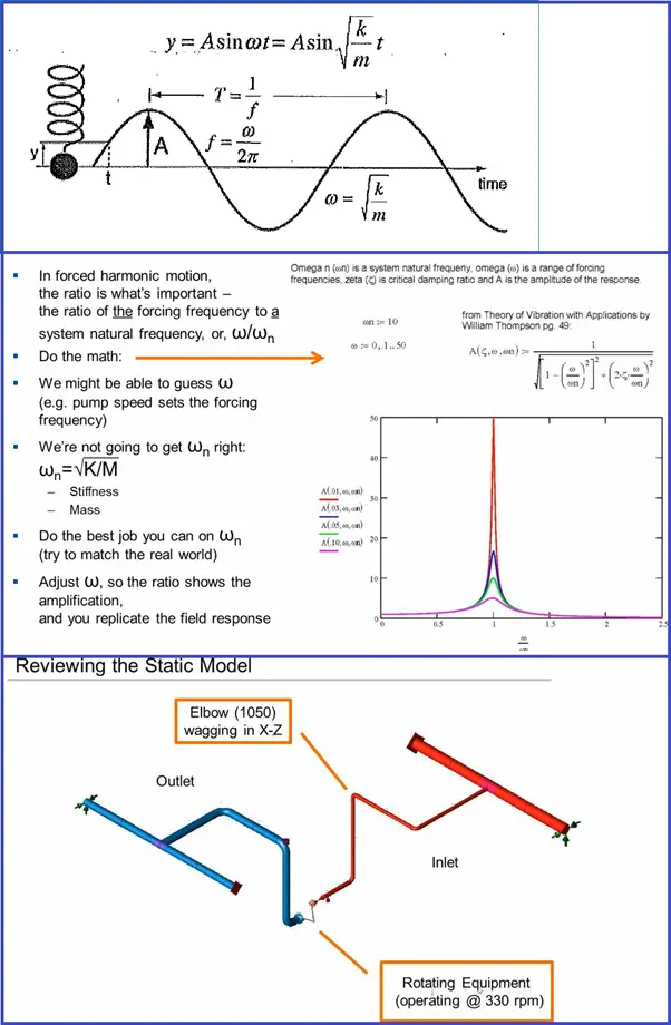
Harmonic analysis is the dynamic analysis used to predict the steady-state dynamic response of the piping system subjected to sinusoidally varying loads. All kinds of externally applied loads like nodal, elemental, gravity, and thermal loads can be included as load input. Accordingly, load cases are required to prepare and included in the solution. Load components in each load case use the same factor and phase angle. Different load cases may have different factors and phase angles, but the frequency for all loads is the same. The points that will be covered in this article are:
Introduction
Reviewing the Static Model
Creating the Harmonic input
The Harmonic Analysis
Result Review
Acoustic vibration and resonance are caused by Positive displacement pumps
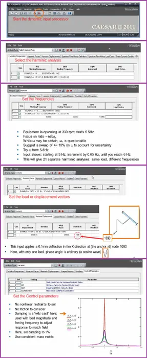
Introduction to Harmonic Analysis
The harmonic analysis considers the effect of a harmonic load being applied to the system. The load is usually applied as a sinusoidal function (Fig. 1), e.g. pressure pulsation from reciprocating equipment. Being of a cyclic nature, harmonic loading relates to the fatigue allowable of the design code and should be considered. Care should be taken when undertaking a harmonic analysis for the accuracy of input data. Information relating to existing field problems can be derived from the measurement of pressure pulsation, deflection, forces, etc.
Reviewing the Caesar II Static Model for Harmonic Analysis
Fig.1: Introduction to Harmonic Analysis
Creating harmonic Input for Analysis in Caesar II
Follow the steps shown in Fig. 2
Fig. 2: Steps for creating harmonic input
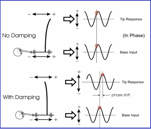
The effect of damping on the response
Fig. 3: Effect of Damping
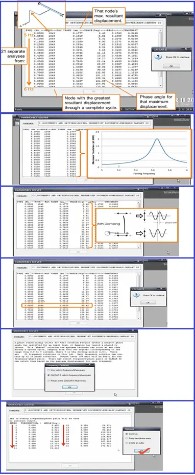
The Frequency-phase Dialog
Fig. 4: The frequency phase dialog
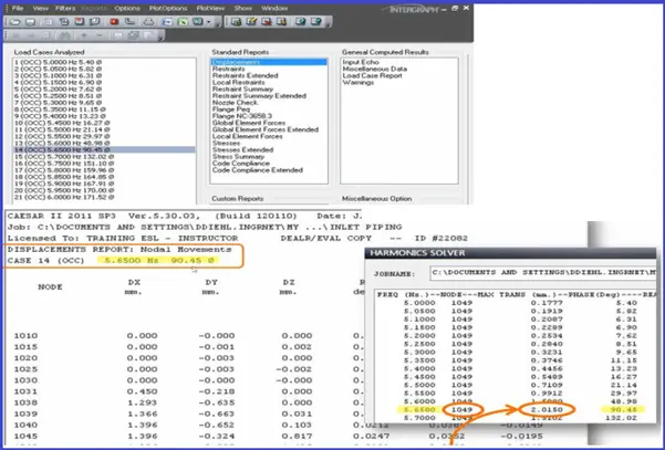
Harmonic Analysis Results Review
Results-Displacements:
Fig. 5: Nodal Movements in Harmonic Analysis
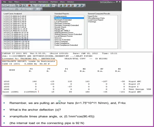
Results-Loads:
Fig. 6: Loads in Harmonic Analysis
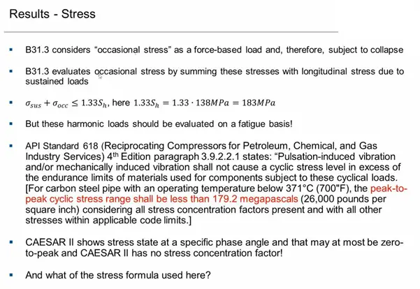
Results-Stress:
Fig.7: Stress Window of Harmonic Analysis in Caesar II
Fig. 8: Occasional Stress
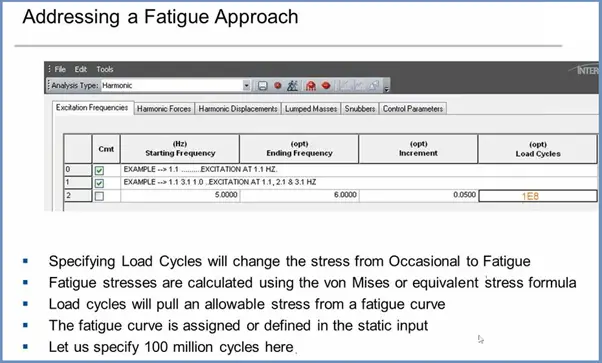
Fig. 9: Fatigue Approach
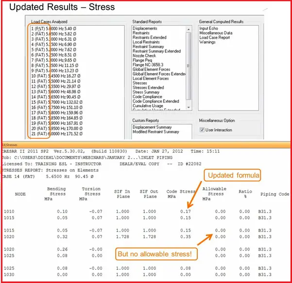
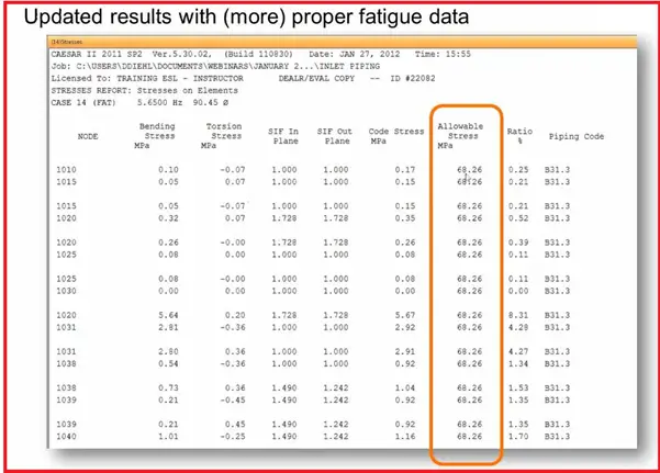
Fig. 10: Updated Stress Results
Fig. 11: Caesar II Steps for adding Fatigue data
Fig. 12: Updated Caesar II output result with Fatigue Data
Author: This presentation is prepared by Mr. Deepak Sethia who is working in ImageGrafix Software FZCO, the Hexagon CAS Global Network Partner in the Middle East and Egypt. He has extensive experience in using Caesar II software and troubleshooting.
Steel pipes are widely used in the process-piping industries. Various grades of steel pipes are available in processing plants. In this article, we will discuss some of those in brief.
Carbon Steel Pipes
(Temperature Range -29 degree centigrade(C) to 427 degrees C)
This is the most common and cheapest material used in process plants. Carbon steels are used in most general refinery applications. It is routinely used for most organic chemicals and neutral or basic aqueous solutions at moderate temperatures. Carbon steels are extensively used in a temperature range of (-) 29 degrees centigrade to 4270 centigrade
Low-Temperature Carbon steel (LTCS) pipes
(LTCS-Temp range -45.5 degrees C to 427 degrees C)
LTCS can be used at a low temperature of (- 45.5) degrees centigrade. Killed Carbon Steel is defined as those which are thoroughly deoxidized during the melting process. Deoxidation is accomplished by the use of silicon, manganese, and aluminum additions to combine with dissolved gases, usually, oxygen, during steelmaking. This results in cleaner, better-quality steel which has fewer gas pockets and inclusions. Killed carbon steel is specified for major equipment in the following services to minimize the possibility or extent of hydrogen blistering and hydrogen embrittlement:
where hydrogen is a major component in the process stream.
where hydrogen sulfide H2S is present with an aqueous phase or where liquid water containing H2S is present.
Process streams containing any amount of Hydrofluoric acid (HF), boron trifluoride (BF3), or (BF) compounds; or
Monoethanolamine (MEA) and diethanolamine (DEA) in solutions of greater than 5 weight percent.
(Temperature range -29 degrees C to 593 degrees C)
Low Alloy Steel pipes contain one or more alloying elements to improve the mechanical or corrosion-resisting properties of carbon steel. Nickel increases toughness and improves low-temperature properties & corrosion resistance. Chromium and silicon improve hardness, abrasion resistance, corrosion resistance, and resistance to oxidation. Molybdenum provides strength at elevated temperatures. Some of the low alloy steels are listed below.
Carbon 1/2% Moly and Manganese 1/2% Moly:
These low alloy steels are used for higher temperature services and most frequently for intermediate temperatures for their resistance to hydrogen attack. They have the same maximum temperature limitation as killed steel (ASME Code 1000 deg. F) but the strength above 700 deg.F is substantially greater.
1% chrome 1/2% Moly and 1 1/4% Chrome 1/2% Moly:
These alloys are used for higher resistance to hydrogen attack and sulfur corrosion. They are also used for services where temperatures are above the rated temperature for C 1/2 Mo steel.
2 1/4 Chrome 1% Moly and 3% chrome 1% Moly:
These alloys have the same uses as 1 1/4% Cr but have greater resistance to hydrogen attack and higher strength at elevated temperatures.
5% chrome 1/2% Moly:
This alloy is used most frequently for protection against combined sulfur attacks at temperatures above 550 deg.F. Its resistance to hydrogen attack is better than 2 1/4% Cr_ 1% Moly.
9% Chrome 1% Moly:
This alloy is generally limited to heater tubes. It has a higher resistance to high sulfur stocks at elevated temperatures. It also has a maximum allowable metal temperature in oxidizing atmospheres.
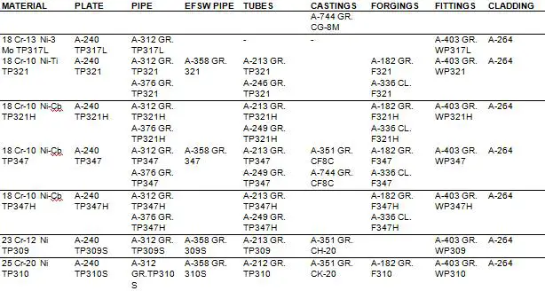
Stainless Steel Pipes
(Temperature range -257 degrees C to 538 degrees C)
They are heat & corrosion-resistant, noncontaminating, and easily fabricated into complex shapes. There are three groups of Stainless steel.
Martensitic Stainless Steel
Ferritic Stainless Steel and
Austenitic Stainless Steel
Martensitic stainless steel pipes
Martensitic alloys contain 12-20 percent chromium with a controlled amount of carbon and other additives. Type 410 is a typical member of this group. These alloys can be hardened by heat treatment, which can increase tensile strength. Corrosion resistance is inferior to Austenitic Stainless steel and these are generally used in mildly corrosive environments.
Ferritic stainless steel pipes
Ferritic steels contain 15-30 percent chromium with low carbon content(0.1 percent). The higher chromium content improves its corrosion resistance. A typical member of this group is Type 430. The strength of these can be increased by cold working but not by heat treatment. Type 430 is widely used in nitric acid plants. In addition, it is very resistant to scaling and high temp oxidation up to 800-degree cent.
Austenitic stainless steel pipes
Austenitic steels are the most corrosion-resistant of the three groups. These steels contain 16-26 percent of chromium and 6-22 percent nickel. Carbon is kept low (0.08 percent max) to minimize carbide precipitation. Welding may cause chromium carbide precipitation, which depletes the alloy of some chromium and lowers its corrosion resistance in some specific environments, notably nitric acid. The carbide precipitation can be eliminated by heat treatment(solution annealing). To avoid precipitation special steels stabilized with titanium, niobium, or tantalum have been developed (Types 321,347 & 348). Another approach to the problem is the use of low-carbon stainless steel such as types 304L & 316L with .03 percent max carbon.
The addition of molybdenum to austenitic alloy (types 316, 316L) provides generally better corrosion resistance and improved resistance to pitting. The chromium-nickel steels, particularly the 18-8 alloys, perform best under oxidizing conditions since the resistance depends on an oxide film on the surface of the alloy. Reducing conditions and chloride ions destroy this and bring on the rapid attack. Chloride ions tend to cause pitting and crevice corrosion. When combined with high tensile stresses they can cause stress-corrosion cracking.