Those who are extensively using Caesar II software must have noted that some Caesar II files got corrupted due to some reason. And modeling the same file from isometric again is time consuming. At the same time, the man-hour used is lost without any fruitful result. The same happened to me yesterday. Unconsciously I deleted the required file and I was a bit worried as I had to redo the modeling again.
In such a situation, you can easily restore the complete Caesar model without much pain. This write-up will try to explain the method of restoring the Caesar II file which is corrupted or deleted by mistake. However, this will only work if you have performed the run function at least once. The load cases that you made will be lost and you have to make new load cases for the analysis. And I feel that’s better as making load cases does not take much time.
Whenever you prepare any Caesar file and then run the file for analysis a backup file of the stress system is automatically generated in the PC. Later that backup file can be used to restore the required Caesar file again. The steps are as follows:
1. Click the open button on Caesar II and you will get the following screen.
2. Now click on the System button on the right side as shown in the above picture.
3. After that page up button on top and you will get the following screen.
4. Now Click on the backup file as shown in the above figure and choose your file. You must remember the file name to restore the same. Choose the latest file as per the date and time to get the most updated information.
5. The Caesar file will be restored for you. Now save that file to the location where you want that to be and make the load cases as per your requirement for analysis. Hope this helps you to resolve a few of your problems and save man hours.
Pumping systems account for nearly 20% of the world’s electrical energy demand. Furthermore, they range between 25-50% of the energy usage in certain industrial plant operations. The use of pumping systems is widespread. They provide domestic, commercial, and agricultural services. In addition, they provide municipal water and wastewater services, and industrial services for food processing, chemical, petrochemical, pharmaceutical, and mechanical industries.
The function of a Pump
Pumps have two main purposes:
Transfer of liquid from one place to another place (e.g. water from an underground aquifer into a water storage tank)
Circulate liquid around a system (e.g. cooling water or lubricants through machines and equipment)
Components of the Pumping System
The main components of a pumping system are:
Pumps (different types of pumps are explained in section 2)
Prime movers: electric motors, diesel engines, or air system
The piping used to carry the fluid
Valves used to control the flow in the system
Other fittings, controls, and instrumentation
End-use equipment, which has different requirements (e.g. pressure, flow) and therefore determines the pumping system components and configuration. Examples include heat exchangers, tanks, and hydraulic machines
Pumping System Characteristics
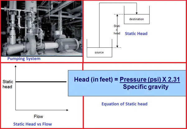
The pressure is needed to pump the liquid through the system at a certain rate. This pressure has to be high enough to overcome the resistance of the system, which is also called the “head”. The total head is the sum of the static head and friction head.
Static head
Static head is the difference in height between the source and destination of the pumped liquid (see Fig. 1)
Static head is independent of the flow (see Fig. 1)
The static head consists of:
Static suction head (hS): resulting from lifting the liquid relative to the pump centerline. The hS is positive if the liquid level is above the pump centerline, and negative if the liquid level is below the pump centerline (also called “suction lift)
Static discharge head (hd): the vertical distance between the pump centerline and the surface of the liquid in the destination tank
The static head at a certain pressure depends on the weight of the liquid and can be calculated with this equation as shown in Fig. 1:
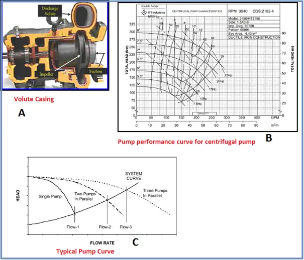
Fig. 1: Pumping System and its Characteristics
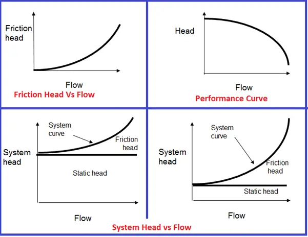
Friction head
This is the loss needed to overcome that is caused by the resistance to flow in the pipe and fittings.
It is dependent on size, condition and type of pipe, number and type of pipe fittings, flow rate, and nature of the liquid.
The friction head is proportional to the square of the flow rate as shown in Fig. 2.
A closed-loop circulating system only exhibits a friction head (i.e. not a static head).
In most cases, the total head of a system is a combination of static head and friction head as shown in Fig. 2. The left figure is a system with a high static head (i.e. the destination reservoir is much higher than the source). The right figure is a system with a low static head (i.e. the destination reservoir is not much higher than the source).
Fig. 2 (Top Left) shows a typical curve of a centrifugal pump where the head gradually decreases with increasing flow.
As the resistance of a system increases, the head will also increase. This, in turn, causes the flow rate to decrease and will eventually reach zero. A zero flow rate is only acceptable for a short period without causing the pump to burn out.
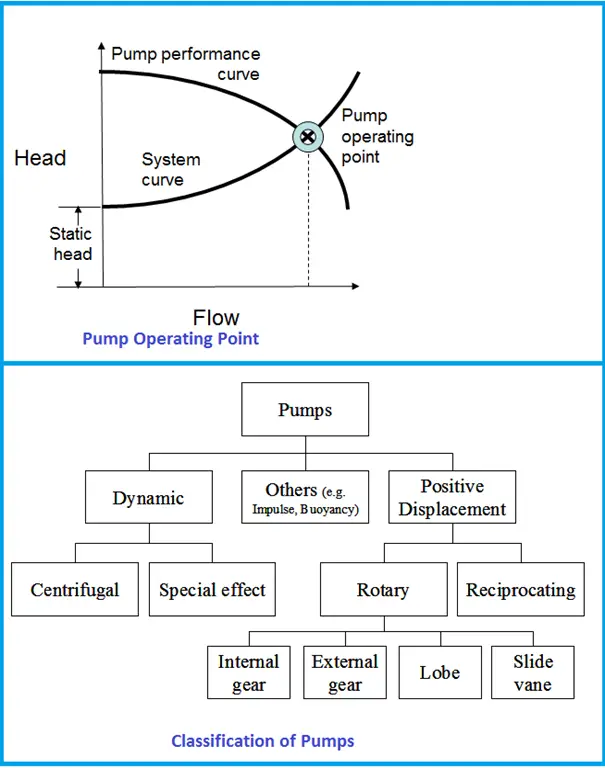
Pump operating point
The rate of flow at a certain head is called the duty point. The pump performance curve is made up of many duty points.
The pump operating point is determined by the intersection of the system curve and the pump curve as shown in Fig. 3
The Best Efficiency Point (BEP) is the pumping capacity at maximum impeller diameter, in other words, at which the efficiency of the pump is highest. All points to the right or left of the BEP have a lower efficiency.
Pump Suction Performance
Pump Cavitation or vaporization is the formation of bubbles inside the pump. This may occur when the fluid’s local static pressure becomes lower than the liquid’s vapor pressure (at the actual temperature). A possible cause is when the fluid accelerates in a control valve or around a pump impeller.
Vaporization itself does not cause any damage. However, when the velocity is decreased and pressure increases, the vapor will evaporate and collapse. This has three undesirable effects:
Erosion of vane surfaces, especially when pumping water-based liquids
Increase of noise and vibration, resulting in shorter seal and bearing life
Partially choking the impeller passages, which reduces the pump performance and can lead to loss of total head in extreme cases.
The Net Positive Suction Head Available (NPSHA) indicates how much the pump suction exceeds the liquid-vapor pressure, and is a characteristic of the system design.
The NPSH Required (NPSHR) is the pump suction needed to avoid cavitation and is a characteristic of the pump design.
Fig. 3: Pump Operating point and Pump classification
Pumps come in a variety of sizes for a wide range of applications. They can be classified according to their basic operating principle as dynamic or positive displacement pumps
In principle, any liquid can be handled by any of the pump designs.
The centrifugal pump is generally the most economical but less efficient.
Positive displacement pumps are distinguished by the way they operate: liquid is taken from one end and positively discharged at the other end for every revolution.
In all positive displacement type pumps, a fixed quantity of liquid is pumped after each revolution. So if the delivery pipe is blocked, the pressure rises to a very high value, which can damage the pump.
Positive displacement pumps are widely used for pumping fluids other than water, mostly viscous fluids.
Positive displacement pumps are further classified based on the mode of displacement:
Reciprocating pump if the displacement is by reciprocation of a piston plunger. Reciprocating pumps are used only for pumping viscous liquids and oil wells.
Rotary pumps if the displacement is by rotary action of a gear, cam, or vanes in a chamber of the diaphragm in a fixed casing. Rotary pumps are further classified as internal gear, external gear, lobe, and slide vane, etc. These pumps are used for special services with particular conditions existing in industrial sites.
Dynamic pumps are also characterized by their mode of operation: a rotating impeller converts kinetic energy into pressure or velocity that is needed to pump the fluid.
There are two types of dynamic pumps:
Centrifugal pumps are the most common pumps used for pumping water in industrial applications. Typically, more than 75% of the pumps installed in an industry are centrifugal pumps.
Special effect pumps are particularly used for specialized conditions at an industrial site.
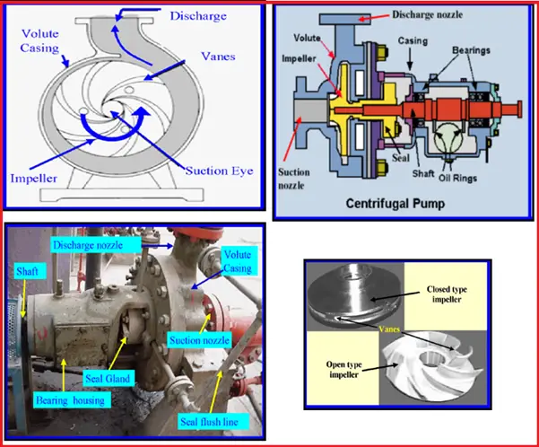
Centrifugal Pumps
A centrifugal pump is one of the simplest pieces of equipment in any process plant. The figure (Fig. 4) shows how this type of pump operates:
The liquid is forced into an impeller either by atmospheric pressure or in the case of a jet pump by artificial pressure.
The vanes of the impeller pass kinetic energy to the liquid, thereby causing the liquid to rotate. The liquid leaves the impeller at high velocity.
The impeller is surrounded by a volute casing or in the case of a turbine pump a stationary diffuser ring. The volute or stationary diffuser ring converts the kinetic energy into pressure energy.
A centrifugal pump has two main components. First, a rotating component comprised of an impeller and a shaft. And secondly, a stationary component comprised of a casing, casing cover, and bearings.
Fig. 4: Centrifugal Pumps
What is an Impeller?
An impeller is a circular metal disc with a built-in passage for the flow of fluid. Impellers are generally made of bronze, polycarbonate, cast iron, or stainless steel, but other materials are also used.
The number of impellers determines the number of stages of the pump. A single-stage pump has one impeller and is best suited for low head (= pressure)
Types of Impellers
Impellers can be classified on the basis of (which will determine their use):
The major direction of flow from the rotation axis
Suction type: single suction and double suction
Shape or mechanical construction: Closed impellers have vanes enclosed by shrouds; Open and semi-open impellers; Vortex pump impellers. Fig. 4 shows an open-type impeller and a closed-type impeller
Shaft
The shaft transfers the torque from the motor to the impeller during the startup and operation of the pump.
The function of the Pump Casings
Casings have two functions
The main function of the casing is to enclose the impeller at suction and delivery ends and thereby form a pressure vessel.
A second function of the casing is to provide a supporting and bearing medium for the shaft and impeller.
Types of Pump Casing
There are two types of casings
Volute casing (Fig. 5-A) has impellers that are fitted inside the casings. One of the main purposes is to help balance the hydraulic pressure on the shaft of the pump.
The circular casing has stationary diffusion vanes surrounding the impeller periphery that convert speed into pressure energy. These casings are mostly used for multi-stage pumps. The casings can be designed as solid casing (one fabricated piece) or split casing (two or more parts together)
Assessment of pumps
The work performed by a pump is a function of the total head and of the weight of the liquid pumped in a given time period. Pump shaft power (Ps) is the actual horsepower delivered to the pump shaft, and can be calculated as follows:
Pump shaft power Ps = Hydraulic power hp / Pump efficiency ηpump
or Pump efficiency ηpump = Hydraulic power / Pump shaft power
Pump output, water horsepower or hydraulic horsepower (hp) is the liquid horsepower delivered by the pump, and can be calculated as follows:
Hydraulic power hp = Q (m3/s) x (hd – hs in m) x ρ (kg/m3) x g (m/s2) / 1000
Where:
Q = flow rate
hd = discharge head
hs = suction head
ρ = density of the fluid
g = acceleration due to gravity
In practice, it is more difficult to assess pump performance. Some important reasons are:
Absence of pump specification data
Pump specification data (see Worksheet 1 in section 6) are required to assess the pump performance. Most companies do not keep the original equipment manufacturer (OEM) documents that provide these data. In these cases, the percentage of pump loading for a pump flow or head cannot be estimated satisfactorily.
Difficulty in flow measurement:
It is difficult to measure the actual flow. The methods are used to estimate the flow. In most cases, the flow rate is calculated based on the type of fluid, head and pipe size, etc, but the calculated figure may not be accurate. Another method is to divide the tank volume by the time it takes for the pump to fill the tank. This method can, however, only be applied if one pump is in operation and if the discharge valve of the tank is closed. The most sophisticated, accurate, and least time-consuming way to measure the pump flow is by measurement with an ultrasonic flow meter.
Improper calibration of pressure gauges and measuring instruments
Proper calibration of all pressure gauges at suction and discharge lines and other power measuring instruments is important to obtain accurate measurements. But calibration has not always been carried out. Sometimes correction factors are used when gauges and instruments are not properly calibrated. Both will lead to incorrect performance assessment of pumps.
Energy efficiency opportunities
This section includes the factors affecting pump performance and areas of energy conservation. The main areas for energy conservation include:
Selecting the right pump
Controlling the flow rate by speed variation
Pumps in parallel to meet varying demand
Eliminating the flow control valve
Eliminating by-pass control
Start/stop control of the pump
Impeller trimming
Selecting the Right Pump
Selecting the Right Pump
Fig. 5-B shows typical vendor-supplied pump performance curves for a centrifugal pump where clear water is the pumping liquid.
In selecting the pump, suppliers try to match the system curve supplied by the user with a pump curve that satisfies these needs as closely as possible.
The operating point is where the system curve and pump performance curve intersect (as explained in the introduction)
The Best Efficiency Point (BEP) is the pumping capacity at maximum impeller diameter, in other words, at which the efficiency of the pump is highest. All points to the right or left of the BEP have a lower efficiency.
Fig. 5: Pump Curves
The BEP is affected when the selected pump is oversized. The reason is that the flow of oversized pumps must be controlled with different methods, such as a throttle valve or a bypass line. These provide additional resistance by increasing friction. As a result, the system curve shifts to the left and intersects the pump curve at another point. The BEP is now also lower. In other words, the pump efficiency is reduced because the output flow is reduced but power consumption is not.
Inefficiencies of oversized pumps can be overcome by, for example, the installation of VSDs, two-speed drives, lower rpm, smaller impeller, or trimmed impeller
Controlling Flow: Speed variation
A centrifugal pump’s rotating impeller generates a head. The impeller’s peripheral velocity is directly related to shaft rotational speed. Therefore varying the rotational speed has a direct effect on the performance of the pump.
The pump performance parameters (flow rate, head, power) will change with varying rotating speeds. To safely control a pump at different speeds it is therefore important to understand the relationships between the two. The equations that explain these relationships are known as the “Pump Affinity Laws”:
Flow rate (Q) is proportional to the rotating speed (N)
Head (H) is proportional to the square of the rotating speed
Power (P) is proportional to the cube of the rotating speed
As can be seen from the above laws, doubling the rotating speed of the centrifugal pump will increase the power consumption by 8 times. Conversely, a small reduction in speed will result in a very large reduction in power consumption. This forms the basis for energy conservation in centrifugal pumps with varying flow requirements.
Controlling the pump speed is the most efficient way to control the flow because when the pump’s speed is reduced, the power consumption is also reduced.
The most commonly used method to reduce pump speed is Variable Speed Drive (VSD).
VSDs allow pump speed adjustments over a continuous range, avoiding the need to jump from speed to speed as with multiple-speed pumps. VSDs control pump speeds using two types of systems:
Mechanical VSDs include hydraulic clutches, fluid couplings, and adjustable belts and pulleys.
Electrical VSDs include eddy current clutches, wound-rotor motor controllers, and variable frequency drives (VFDs). VFDs are the most popular and adjust the electrical frequency of the power supplied to a motor to change the motor’s rotational speed.
The major advantages of VSD application in addition to energy-saving are:
Improved process control because VSDs can correct small variations in flow more quickly.
Improved system reliability because wear of pumps, bearings, and seals is reduced.
Reduction of capital & maintenance costs because control valves, by-pass lines, and conventional starters are no longer needed.
Soft starter capability: VSDs allow the motor to have a lower startup current.
Parallel Pumps for Varying Demand
Operating two or more pumps in parallel and turning some off when the demand is lower, can result in significant energy savings. Pumps providing different flow rates can be used.
Parallel pumps are an option when the static head is more than fifty percent of the total head.
The Fig. 5 shows
the pump curve for a single pump, two pumps operating in parallel, and three pumps operating in parallel.
that the system curve normally does not change by running pumps in parallel.
that flow rate is lower than the sum of the flow rates of the different pumps.
Eliminating Flow Control Valve
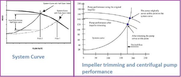
Another method to control the flow is by closing or opening the discharge valve (this is also known as “throttling” the valves).
While this method reduces the flow, its disadvantages are
It does not reduce the power consumed, as the total head (static head) increases. Fig. 6 shows how the system curve moves upwards and to the left when a discharge valve is half-closed.
increases vibration and corrosion and thereby increasing maintenance costs of pumps and potentially reducing their lifetimes
VSDs are a better solution from an energy efficiency perspective.
Eliminating By-pass Control
The flow can also be reduced by installing a bypass control system, in which the discharge of the pump is divided into two flows going into two separate pipelines. One of the pipelines delivers the fluid to the delivery point, while the second pipeline returns the fluid to the source. In other words, part of the fluid is pumped around for no reason, and thus is an energy wastage. This option should, therefore, be avoided.
Start / Stop Control of Pump
A simple and reasonable energy-efficient way to reduce the flow rate is by starting and stopping the pump, provided that this does not happen too frequently. An example where this option can be applied is when a pump is used to fill a storage tank from which the fluid flows to the process at a steady rate. In this system, controllers are installed at the minimum and maximum levels inside the tank to start and stop the pump. Some companies use this method also to avoid lowering the maximum demand (i.e. by pumping at non-peak hours).
Impeller Trimming
Changing the impeller diameter gives a proportional change in the impeller’s peripheral velocity
Changing the impeller diameter is an energy-efficient way to control the pump flow rate. However, for this option, the following should be considered:
This option cannot be used where varying flow patterns exist.
The impeller should not be trimmed more than 25% of the original impeller size, otherwise, it leads to vibration due to cavitation and therefore decrease the pump efficiency.
The balance of the pump has to be maintained, i.e. the impeller trimming should be the same on all sides.
Changing the impeller itself is a better option than trimming the impeller, but is also more expensive and sometimes the smaller impeller is too small.
Figure 6 illustrates the effect of impeller diameter reduction on centrifugal pump performance.
Fig. 6: Centrifugal pump Performance
Figure 6 illustrates the effect of impeller diameter reduction on centrifugal pump performance.
With the original impeller diameter, the flow is higher
With the trimmer impeller, the flow is lower
Parameter
Change control valve
Trim impeller
VFD
Impeller diameter
430 mm
375 mm
430 mm
Pump head
71.7 m
42 m
34.5 m
Pump efficiency
75.1%
72.1%
77%
Rate of flow
80 m3/hr
80 m3/hr
80 m3/hr
Power consumed
23.1 kW
14 kW
11.6 kW
The above table compares three options to improve energy efficiency in pumps:
changing the control valve, trim the impeller and variable frequency drive.
The VFD clearly reduces power most, but a disadvantage is the high costs of VFDs.
Changing the control valves should at all times be avoided because it reduces the flow but not the power consumption and may increase pump maintenance costs.
This article covers the design consideration of emergency response procedures and measures in petroleum refineries, chemical plants, and similar plants. This can be used in conjunction with the Job Specification, the client’s standards and intent, the licensor’s instructions, and related regulations. This article describes the emergency response design consideration of the following emergency measures.
Of the various measures for protecting a plant from the emergency situation, pressure-relieving through safety valves and rupture discs shall be examined first. This part will be covered in separate articles.
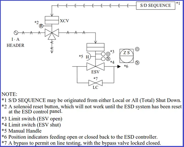
Isolation with Emergency Shut-off Valve
This section describes the installation standards of Emergency Shut-off (Block) Valves (ESV)used for isolating the equipment from the units in an emergency.
First, the following should be clarified with the client.
Client’s general philosophy for safety
Reliability for sensor(application of 2 out of 3 or not etc.)
Category of ESV (local, all shut down, etc.)
Inspection under operation (bypass or parallel installation)
The purpose of isolation by ESV is classified into the following.
Equipment Protection (Vessel, Tower)
Heat Off (Furnace, Steam supply)
Fluid or Seal gas Cut(Compressor, Pump), Leak Air Cut (Vacuum Pump)
Emergency Response Plan forVessels
ESV is not always necessary to be provided on the Vessel outlet line.
If both the vessel volume of liquid and fluid condition meet the following requirements, ESV shall be provided on Vessel outlet lines.
(a) Vessel volume-This limitation should be verified with project specifications.
Liquid both flash point below 22.8°C and boiling point below 37.8°C
LPG, Naphtha, liquid with temperature more than auto ignition temp.
A control valve with a solenoid valve may be used as ESV if the following conditions are met:
It is not equipped with a minimum stop
It will close on the failure of the air supply or power failure.
A leak amount of CV is allowable.
The client’s approval is obtained
Emergency Responses for Furnaces
Fuel lines to process furnaces and steam boilers shall be provided with remotely operated emergency valves.
In addition to the above, a manually operated block valve shall be provided in each fuel line. This includes the pilot gas supply line if it is a separate line. These valves shall be located at least 15 meters horizontally from the furnace or boiler protected.
ESV (Emergency shut-off valve) on the snuffing steam line shall be located at least 15 meters horizontally from the furnace and operable from grade.
Emergency responses for Steam Line to Reboiler
ESV will be installed on the steam inlet line to Reboiler especially in the case when the control valve is installed on the Reboiler outlet condensate line.
Emergency Measures for Compressors
ESV shall be provided in the suction and discharge lines of centrifugal compressors to prevent seal gas leakage.
(2) Other specifications for ESV installation are as below.
In case when Control Valve closing time is too slow. (Cost study is necessary)
A Balance line with ESV between suction and discharge may be requested by the client.
Emergency Response Plan for Pumps
ESV will be provided in the suction line of Pumps. (Treated as Vessel Outlet ESV)
ESV may be installed on the discharge line of high-head pumps to prevent backflow.
Emergency Response Guidelines: Vacuum Pumps
In the case of the NASH Pump, ESV will be installed on the suction line (process side) of Vacuum Pumps to prevent seal liquid from backflow into the process.
Emergency Measures: Depressurizing
When metal is exposed to fire, the metal temperatures may reach a level at which stress rupture could occur. The use of an emergency vapor depressurizing system is one method of avoiding such an occurrence.
Design Base of Vapor Depressurizing
The design base of vapor depressurizing is as follows. (Refer to API RP 520, 521)
Depressurizing Valve is of a remotely operated type.
Depressurizing initial pressure may be assumed up to design pressure.
The depressurized level should beat 7.0 kg/cm2 G or 50% of vessel design pressure, whichever is lower.
The duration time of depressurizing should be 15 minutes with a wall thickness of 25 mm, while vessels with thinner walls generally require a somewhat greater depressurizing rate.
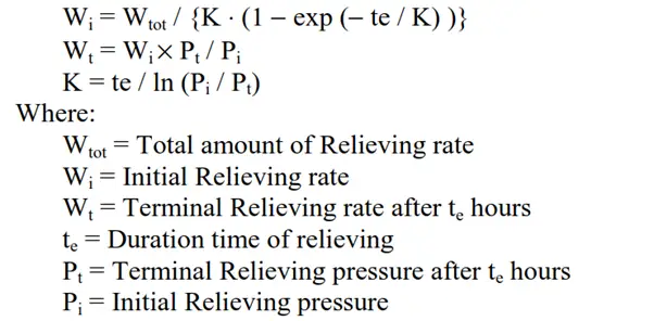
Total Vapor Depressurizing Load:
The total vapor load will be obtained as the summation of the following.
Vapor generated from the liquid by heat input from a fire
Density change of the vapor in the equipment during pressure reduction, plus
Liquid flashing during pressure reduction
Design Consideration:
For the recycle compressor stoppage, settling out pressure should be investigated.
Excessive hot depressurizing gas should not be introduced to the flare header. Cooling should be provided in such a case.
As for the temperature effect due to hot depressurizing gas, it is not necessary to take it into account for the determination of the design temperature of each piece of equipment because of short-term conditions. However thermal stress checks of related piping should be necessary as required.
Regarding both pressure and flow rate change along with traveling time, the following tentative method may be available.
Relieving Rate Calculation
The dynamic simulation should be carried out to confirm:
Reactor mechanical bed pressure checks during Depressurizing.
H/E with differential pressure design.
Mechanical damage for Compressor Seal Oil etc.
(NOTE) In the case of Manual Depressurizing with HCV, the above is not necessary.
Emergency Response Procedure: Alarm and Trip System
(a) Alarm and trip signals are indicated on DCS or CCR panel. When the signal tells abnormal situations happened, it is expected that the operator takes appropriate countermeasure actions in accordance with the operating manual.
(b) As for compressor and other package units, alarm and trip signals are indicated on the local panel. Only common alarm and trip signals are indicated on DCS or CCR panel. It is expected that the operator explores the cause of the failure at the local panel and takes appropriate actions in accordance with the operating manual.
(c) Each ESD (Emergency Shut Down) shall be independent of the distributed control system (DCS) and may be activated either by plant transducers (eg. high pressure, low flow) or manually from CCR.
(d) Typical set point for level alarm and level trip
– High / Low alarms at 80% and 20% of the range
– High / Low trips at 90% and 10% of the range
A dedicated level switch is provided for the level trips.
A minimum of 5 minutes will be available for the operator’s intervention after a high or low-level alarm is actuated and before gas breakthrough or liquid flooding takes place. Or an independent ESV is provided for the operator to initiate manually to close the outgoing flow. (to be confirmed by the process engineer)
(e) Setpoint for temperature and pressure alarm and trip.
– As specific to the project, contents shall be individually investigated and clarified.
Emergency Response Procedure: Failures & Trips
The failures for units and equipment, as also trip actions are summarized under the following categories.
Furnaces
Pumps including Hydraulic Power Recovery Turbine
Compressors
The trip sequence is summarized on the PID. It is necessary, however, to prepare the sequence logic diagram at the same time. Also, it is desirable to explain the outline of the trip sequence in the operation manual. Typical TRIP SEQUENCE is as follows.
Trip Sequence
Motion Amplification Technology (MAT) for Piping Vibration Visualization
Iris M from RDI technologies is the first device of its kind that allows users to see – in real-time – the motion that is unseen to the human eye. This patented Motion Amplification Technique lets you see the invisible.
Iris M is a unique, revolutionary technology that detects subtle motion and amplifies that motion to a level visible to the naked eye. By turning every pixel in the camera into a sensor, Iris M takes millions of measurements in a fraction of a second with no physical connection to the machinery or equipment. Motion Amplification™ is a proprietary video processing algorithm that detects subtle movement and then converts that movement to a level visible to the naked eye which enhances the understanding of the components and interrelationships creating the motion.
In a typical traditional data acquisition process, we have to fix the sensors at predefined locations on the machinery or equipment. The data collection is non-simultaneous and prepares a report with a detailed explanation or exception list with spectra and waveforms.
In this revolutionary technology – Iris M, data are collected by a high-speed machine-grade camera in the form of standard video. It measures the movement not visible to the naked eye by turning each pixel into a sensor that measures vibration and motion. It used patented methods and processing algorithms to extract meaningful data. The data is simultaneous and gives a report with detailed displacement and frequency spectrums.
Iris M Platform monitors critical manufacturing operations, processes, quality, piping, and structural components that affect plant reliability and productivity. It is a perfect tool for screening, fault finding, baseline or commissioning, and pre/post repairs or retrofits.
Benefits of Motion Amplifications
Improved Safety: Totally non-contact
Reduce unplanned downtime: Know what your “Bad Actors” are doing
Complimentary Tool
Diverse applications – Machines, Structures, Processes, Piping, Visual ODS
Setup & acquire data in minutes, easy to deploy, use often as a troubleshooting tool
Actionable information: Results are easy to see in a standard video
Communications with facility resources are enhanced
The World’s First Non-Contact Motion Amplification Platform – Iris M
Thermowells are cylindrical pressure-tight fittings used to protect the temperature sensors such as thermocouples, thermistors, and bimetal thermometers which are inserted into a pipe or vessel in industrial applications. A thermowell is basically a tube closed at one end and mounted in the process stream. The thermowell acts as a barrier between the sensing element and the process medium. It protects the sensing element against corrosive process media and fluid pressure and velocity.
Thermowells also increase the sensor longevity, allow sensor replacement without draining the system and eliminate the probability of contamination. Thermowells are designed for both high and low-pressure applications.
Thermowells find wide applications in many industrial sectors including refining, cosmetics, petrochemical, food processing, chemicals, Power, pharmaceutical, and other process industries.
Thermowells ensure that process temperature is passed to the sensor (proper heat transfer).
Improved heat transfer, results in better accuracy.
Allow the removal of the sensing element while maintaining a closed system.
Types of thermowell
Thermowells in the piping industry can be classified based on various parameters as listed below:
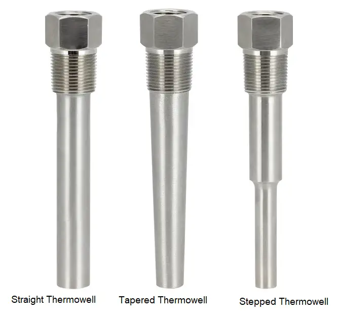
Depending on the stem design shape, four types of thermowell are available:
Straight Thermowell
Stepped thermowell
Tapered Thermowell, and
Built-up thermowells
Straight Thermowell
Straight thermowell has the same diameter for the entire insertion length. They are simple to fabricate and possess good rigidity and offer protection against corrosion and erosion.
Stepped Thermowell
Stepped thermowell have stepped diameters; Normally at the tip, they have a smaller (typically 1/2″) diameter while a larger diameter (Typically 3/4″) at the top. Due to decreased thermal inertia at the process end, these thermowells allow smoother velocities and respond more rapidly to temperature changes than their straight counterparts.
Tapered Thermowell
The tapered thermowell has varying diameters (smooth continuous taper) over its full insertion length. Tapered thermowell is suitable for high-velocity heavy-duty applications and possesses a fast response time.
Built-up Thermowell
Built-up thermowells are suitable for very long process insertion lengths. They are available in all the above types but a length of pipe is welded between the tip and process connection to give the long insertion length.
Fig. 1: Types of Thermowells
Depending on material types, Two types of Thermowells can be found:
Pipe Fabricated.
Bar stock thermowells.
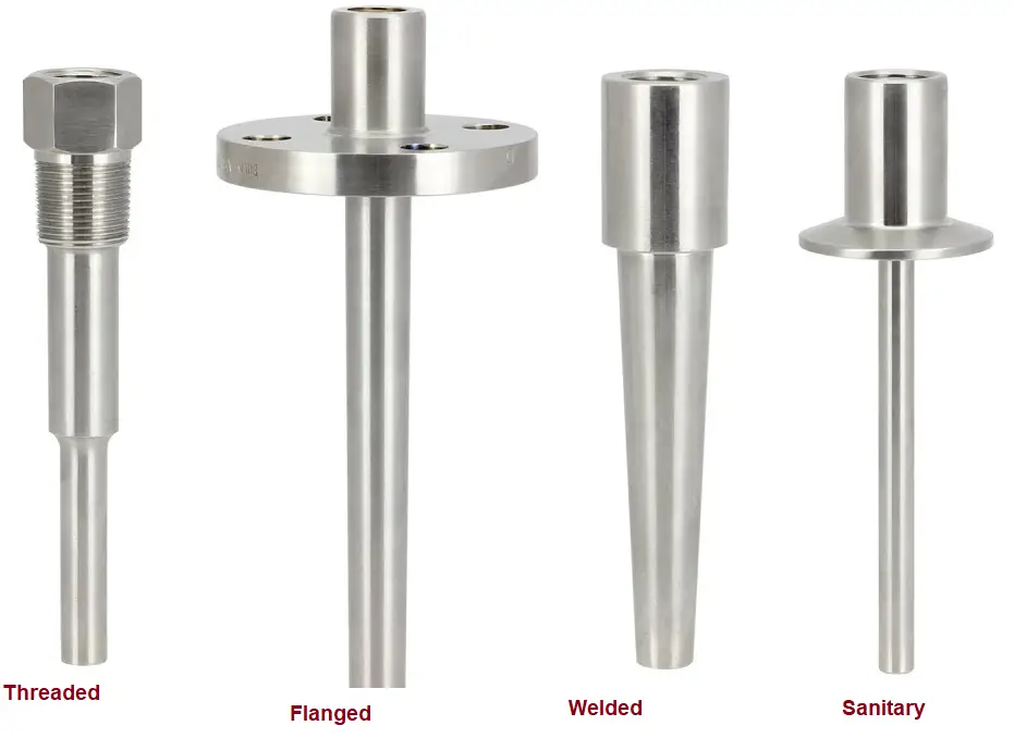
Depending on thermowell end connections, five types of thermowells are available. they are
Threaded thermowells
Weld-In thermowells
Socket Weld thermowells
Van Stone or Lap Joint flanged thermowells
Flanged thermowells
Threaded Thermowell
The threaded type thermowell is generally the least costly and most versatile. Threaded thermowells are normally used for non-corrosive applications. They are screwed into the pipe. Their material is such that it can be welded or brazed to provide additional strength.
Weld-in Thermowell
Weld-in thermowell connections are preferred for food and pharmaceutical industries where contaminants from threads must be avoided.
Socket Weld Thermowell
Socket Weld Thermowells are directly welded into the pipe. Its strong connection helps these thermowells to use as a permanent connection. Applications involving very high temperature and pressure use socket-welded thermowell connections.
Van Stone Thermowell
For high-pressure applications, the Van Stone thermowell is ideal. They are usually machined from a solid bar and are placed in a sandwich position between the nozzle and cover flange. Vanstone flange surface is with a phonographic spiral serration.
Flanged Thermowell
A flanged thermowell is designed with a flange at the top end. This type of thermowell is connected to the pipe using nuts and bolts. Flanged thermowell connections are mostly used in high-temperature applications that require frequent replacements.
Flanged thermowells are used in a wide range of industrial applications where temperature measurement is critical. The flange design allows for easy installation and removal of the thermowell without interrupting the process or requiring any special tools.
Some common applications of flanged thermowells include:
Chemical processing: Flanged thermowells are used to measure the temperature of various chemicals in reactors, vessels, and pipelines.
Oil and gas: Flanged thermowells are used in oil refineries, pipelines, and gas processing plants to measure the temperature of crude oil, natural gas, and other hydrocarbons.
Food and beverage: Flanged thermowells are used in food and beverage processing plants to measure the temperature of liquids, such as milk, beer, and juice.
HVAC: Flanged thermowells are used in heating, ventilation, and air conditioning (HVAC) systems to measure the temperature of air and water.
Power generation: Flanged thermowells are used in power plants to measure the temperature of steam and other fluids used in power generation.
Pharmaceutical: Flanged thermowells are used in pharmaceutical manufacturing processes to measure the temperature of various chemicals, drugs, and biological products.
Overall, flanged thermowells are used in any process where temperature measurement is critical and the protection of the temperature sensor is required from harsh process conditions.
There are two other types of thermowell connections; Scruton thermowell and Sanitary thermowell.
Scruton Thermowell
To avoid damages that can be caused due to the mechanical load and critical condition of the process, the Scruton thermowell is designed. They save time and cost on re-work at the site.
Sanitary Thermowell
A sanitary thermowell is used for isolation and protection of the sensing element of any temperature instrument. To avoid bacterial build-up, Sanitary thermowells are built with hygienic connection.
Fig. 2: Thermowell types based on End Connection
Materials of Thermowells
The right material increases the longevity of a thermowell. Material selection of thermowell will depend on the chemical, temperature, and flow rate of the process fluid. With an increase in temperature and fluid concentration, the corrosive effects of chemicals normally increase. At the same time, suspended particles of the fluid will cause erosion. So all these parameters need to be addressed while selecting thermowell material. Some of the most frequently used thermowell materials are listed below:
Carbon Steel
Brass
SS 316 / SS 304
SS316 with Teflon / Zirconium Coated or Tantalum / Titanium steathing.
However, the most widely used thermowell material is stainless steel as it is cost-effective and highly resistant to heat and corrosion. For pressurized vessels, Chromium/molybdenum steel is used. Cobalt, nickel, chromium, and tungsten constitute the Haynes alloy that is widely used for sulphidising, carburizing, and chlorine-containing environments. The use of carbon steel thermowell is only limited to low-temperature pressure applications due to its very low resistance to corrosion.
Thermowell Insertion Length
The length from the connection point to the thermowell tip is known as the insertion length of the thermowell (U dimension in Fig. 4). For better accuracy, the thermowell insertion length should be long enough. This will allow the entire temperature-sensitive portion of the measurement device to extend into the medium being measured.
For measuring the liquid temperatures using a temperature sensor, the device must be extended into the solution for the length of the temperature-sensitive portion plus a minimum of one inch (25 mm). For gaseous or air service, it should be immersed for the length of the temperature-sensitive segment plus an additional three inches. The temperature-sensitive section of a thermocouple or thermistor is short; therefore, the insertion length of the thermowell can be shorter for these devices. Whereas, the temperature-sensitive section of bimetal thermometers, RTDs, and liquid in glass thermometers is between 1″ and 2″ hence, the thermowells must be immersed at least 2½” in liquid for accurate measurements.
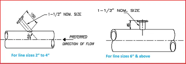
Thermowell Installation
Lagging is used when the thermowell is installed through an insulation media on a pipeline or equipment.
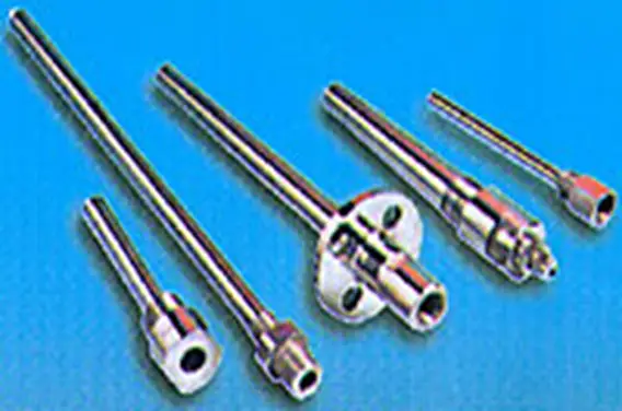
Fig. 3: Examples of Thermowells
An improperly specified thermowells, will result in:
Failure due to poor welding practices.
Poor compatibility with the temperature and media.
Inadequate temperature transfer.
Incompatibility with the process velocity leads to failure due to vibration.
The gap between the OD of the thermocouple sheath and the ID of the thermowell must be very close.
The bore of the thermowell must be uniform and linear.
Design of Thermowells
The design of the thermowell should cater to process media, pressures, temperatures, velocity, specific gravity, etc.
Proper MOC (Material of construction).
Wall thickness Vs response time.
Bore diameter, Insertion length, Taper requirements, Overall length, etc.
Vortex shedding
Calculate the Vibration using Wake Frequency methods.
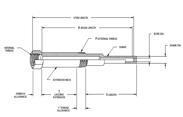
Fig. 4: Details of Thermowell
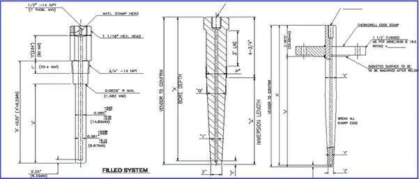
Fig. 5: Various dimensions of Thermowells.
Thermowell Installation Requirements
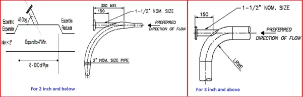
Refer to Fig. 6 and Fig. 7
Fig. 6: Requirements during installation
Fig. 7: Installation Requirements
Selection of a Thermowell
The key parameters to consider while selecting a thermowell are:
Process connection size and type.
Process insertion length
Lagging length
Extension length
Sensor length
Interior diameter (bore) for the sensor or thermometer
Internal threads for the sensor or thermometer
The shape of the thermowell (straight, stepped, tapered, built-up)
Material of construction
Thermowell Design Code
Piping Designers follow ASME PTC 19.3 for guidelines regarding thermowells.
Thermowell Working Principle
The working principle of a thermowell is based on the concept of thermal conductivity, where heat flows from a region of high temperature to a region of low temperature. A thermowell is a protective casing that is used to house a temperature sensor, such as a thermocouple or a resistance temperature detector (RTD). The thermowell is inserted into the process being measured, and the temperature sensor measures the temperature of the process fluid or environment.
The thermowell is designed to protect the temperature sensor from harsh process conditions, such as high pressure, high temperature, and corrosive fluids. The thermowell is typically made of durable material, such as stainless steel or ceramic, and has a closed end that protects the temperature sensor from direct contact with the process fluid. The thermowell also has an opening that allows the temperature sensor to come in contact with the process fluid and measure the temperature.
The thermowell works by allowing the heat from the process fluid to flow through the wall of the thermowell and come into contact with the temperature sensor. The thermal conductivity of the thermowell material is chosen such that it allows for efficient heat transfer while also providing adequate protection for the temperature sensor. The thermowell also serves to isolate the temperature sensor from the process fluid, allowing for accurate temperature measurement even in harsh process conditions.
Overall, the thermowell working principle is based on the concept of thermal conductivity, where the thermowell material allows for efficient heat transfer while protecting the temperature sensor from harsh process conditions.
Thermowell Vibrations
As thermowells are immersed in the process flow, a bending force will be experienced by them. Additionally, depending on the fluid velocity and thermowell diameter, a certain vibrational frequency will be generated leading to thermowell vibration. In general, such vibrations are of small magnitude and considered negligible. But, the thermowell must have sufficient stiffness and rigidity to absorb those vibrations. In such a scenario, tapered thermowells are preferred as they have more stiffness. However, if the generated frequency approaches the natural frequency of the thermowell, it can cause severe unacceptable vibrations. ASME PTC 19.3 provides formulas to determine if a thermowell is acceptable for a given application. Many thermowell manufacturers have generated a velocity rating table that recommends the maximum fluid velocity for their thermowells to avoid resonance.
Wake frequency calculation following the guidelines of ASME PTC 19.3 standard is performed to prove that the thermowell has the strength to handle hydrostatic pressure limit and dynamic static stress in relation to process conditions. Prior to the manufacturing of thermowell, these types of calculations ensure that the thermowells can cope with the stress and strain produced by any kind of process media.
Information required for Purchasing Thermowell
The following information must be supplied to the thermowell manufacturer/vendor while placing an order.
Process Connection Size
Thermowell Insertion Length
Lagging extension
Shank configuration
Process Connection type
Nominal Bore
Thermowell Material
Process Design temperature and pressure
Disadvantages of Thermowell
The main disadvantages of a thermowell are:
Compared to a naked sensor, slightly slower response to temperature changes.
Resistance to flow medium.
Increased cost for purchasing a thermowell.
Differences between a Thermowell and a Thermocouple: Thermowell vs Thermocouple
A thermowell and a thermocouple are both used for temperature measurement, but they are different in their design, function, and application. Here are some of the main differences between the two:
Design: A thermowell is a protective tube that is inserted into a process or fluid to provide a barrier between the sensor and the environment. A thermocouple, on the other hand, is a sensor that measures temperature by generating a small voltage in response to a temperature difference.
Function: The purpose of a thermowell is to protect the temperature sensor, usually a thermometer or a thermocouple, from damage or corrosion in harsh environments, high pressures, or high-velocity fluid flows. The thermowell provides a barrier between the sensor and the environment while allowing the sensor to detect the temperature of the process fluid. A thermocouple, on the other hand, is a sensor that directly measures temperature by generating a voltage in response to a temperature difference.
Application: Thermowells are typically used in process industries such as oil and gas, chemical processing, and food and beverage production. They are often used to protect temperature sensors that are installed in pipelines, tanks, and vessels. Thermocouples, on the other hand, can be used in a wide range of applications, including temperature monitoring in HVAC systems, laboratory equipment, and industrial processes.
In summary, a thermowell is a protective barrier that surrounds a temperature sensor, while a thermocouple is a temperature sensor that directly measures temperature. They have different functions and applications but can both be used for temperature measurement in various industries and applications.
Thermowell Probe
A thermowell probe is a temperature measurement device that consists of a temperature sensor, such as a thermocouple or a resistance temperature detector (RTD), housed inside a protective tube called a thermowell. The thermowell is typically made of metal and is inserted into a process or fluid, providing a barrier between the temperature sensor and the environment. The thermowell is designed to protect the temperature sensor from damage or corrosion caused by harsh process conditions such as high temperatures, high pressures, and corrosive fluids.
The thermowell probe allows temperature measurement without directly exposing the temperature sensor to the process fluid or environment. The thermowell can be removed and replaced if necessary without affecting the process or equipment, making it a useful tool in many industries, including chemical, oil and gas, and food and beverage production. The selection of a thermowell probe depends on factors such as the process conditions, the type of temperature sensor used, and the required accuracy and response time.
Thermowell Temperature Sensor
A thermowell temperature sensor is a device that measures temperature using a thermowell as a protective barrier between the temperature sensor and the process fluid or environment. The temperature sensor can be a thermocouple or a resistance temperature detector (RTD) and is typically housed inside the thermowell, which is inserted into the process or fluid being measured. The thermowell protects the temperature sensor from damage caused by harsh process conditions such as high temperatures, high pressures, and corrosive fluids.
The thermowell temperature sensor is commonly used in industries such as chemical processing, oil and gas, and food and beverage production, where accurate temperature measurement is essential for maintaining the quality and safety of products and processes. The thermowell temperature sensor can be installed directly into pipelines, tanks, and vessels, allowing temperature measurement of liquids, gases, and solids. The thermowell can be designed to meet various requirements, such as high temperature and pressure ratings, different materials of construction, and various process connections. The selection of a thermowell temperature sensor depends on factors such as the process conditions, the type of temperature sensor used, and the required accuracy and response time.
A pipe rack is a very important part of process piping. A Pipe Rack can be defined as a steel-framed structure that supports and carry pipes inside the processing plant and transfer the fluid between equipment and storage facilities or utility areas.
While designing a pipe rack, there are two main factors into which a stress engineer should look at details. Those are
The following write-up will list the considerations while designing the pipe loop and rack loading.
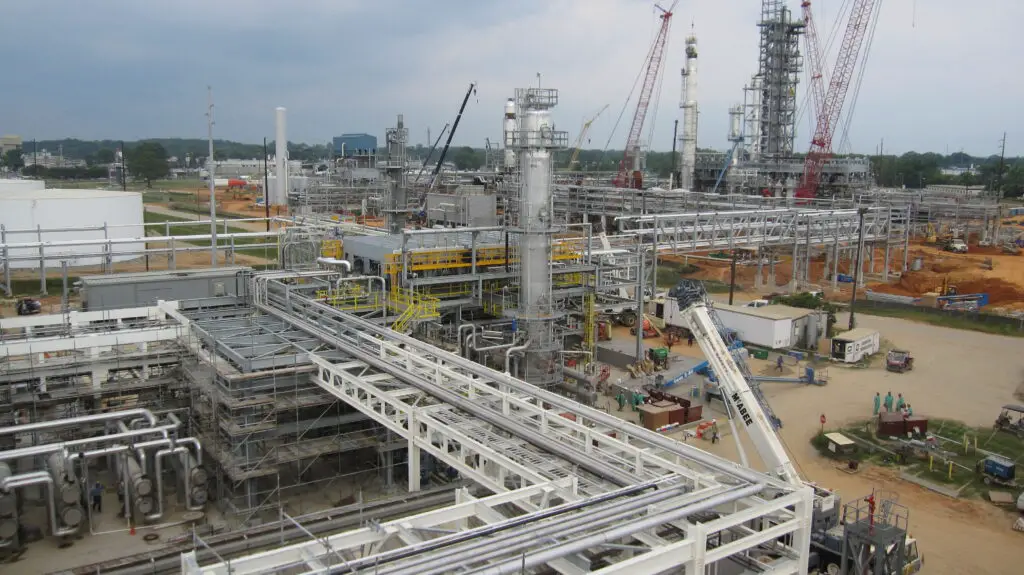
Fig. 1: A typical Pipe rack in a Process Plant
Expansion Loop design and placement
In most organizations, there are no defined criteria for designing and placing an expansion loop in a pipe rack. So most of the time the expansion loop is designed and located based on user experience. The important parameters which govern the design of the expansion loop are listed below:
A. Design/Maximum operating temperature of the line
B. Allowed Displacement or movement (Normally allowed thermal displacement is 250-300 mm inside a loop and 75-100 mm in outside turns)
C. Allowed Expansion stress (normally within 80% of code allowable)
D. Line size (Bigger sizes require more leg to absorb expansion)
E. Loop Supporting Requirements (locations at which the loop will be supported)
F. Fluid type (Normally Flare and condensate lines require a 2D loop)
G. Line sagging criteria from Project specification (Sometimes Steam, Condensate, Two-Phase flow lines, and Flare lines require sagging limited within 3-5 mm for others it can go up to 15 mm)
H. Rack length and width
After having the above-mentioned parameters ready one can proceed to locate the loops over the rack. Follow the below-mentioned steps as a preliminary guideline:
a. Select an elevation of the pipe rack and check what the lines running over that rack.
b. Select the line with maximum temperature first. Check the allowed maximum movement outside loop (say 75 mm) and place the first anchor at a distance that will be nearer to the allowed thermal movement (75 mm) as mentioned above.
c. Now as one anchor is fixed one can easily calculate the thermal displacement at design temperature towards the other end/turn. If the displacement is within the allowed displacement (75mm) then an expansion loop is not required. But if the calculated displacement is more (>75mm) then the expansion loop is required. From this displacement, you can decide how many expansion loops are required for the straight run allowing a maximum of 250-30 0mm displacement inside the loop. (Care should be taken for expansion leg requirement as sometimes allowing 300 mm displacement may cause expansion failure or huge anchor load. In that case, increase the number of expansion loops.)
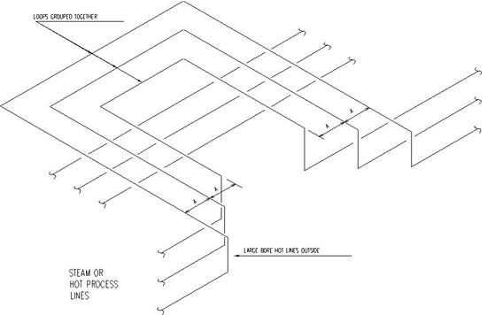
d. It is better to place lines with high temperatures outside of the rack so that a longer loop length can be achieved on the other side.
e. It is better to nest the loops in a single location (the same structures can be utilized for supporting)
f. Don’t mix lines that required 2D loops with lines that required a 3D loop in the same elevation.
g. It is better to place anchors in similar locations for deciding anchor bay.
Fig. 2: Typical Expansion Loop
h. After deciding the loops check the loop length requirements from Pipe-Data-Pro, Caesar modeling (most optimized approach), Nomograph, Manual calculation, etc.
Rack loading is provided to CSA for the economic design of the pipe rack. Providing pipe rack loading is a very difficult task for a stress engineer as most of organizations do not have any guidelines. Normally Pipe rack loads are transferred in 3 stages:
a. Initial rack loading for rack foundation design (before piling): The project has just started and very little data is available. The piping design places the lines over the rack based on preliminary P&ID. Rack loads are provided mostly based on assumption/experience. Conservative loads are to be provided.
b. Rack loading for member sizing (after 30% model review): Most of the data has started arriving. Loads are to be provided based on actual analysis.
c. Rack loading for final member checking (after 60% model review): All vendors are decided. Line size and locations are finalized. All critical lines are fixed. Loads are provided for checking designed members again. Loads are to be provided based on Software analysis.
Few points to keep in mind while providing Rack loading:
1. Operating, Water filled, and Occasional loads for big-size lines (> 16-inch NPS) are to be provided separately. For guides and anchors, loads with and without friction should be provided.
2. For the Flare line 1/3rd water-filled weight can be considered.
3. Proper directions to be marked.
4. After the long run doesn’t provide a guide in the immediate first possible location after the bend.
5. Consider concentrated loads of inline valves, flanges, equipment, etc.
6. Sometimes large equipment is placed over the pipe racks (Air Fin Fan Cooler, Heat Exchangers, etc). So take the operating weight of equipment from the mechanical group.
7. Cable tray loads are to be taken from the electrical/instrumentation group. (In absence of data a uniformly distributed load of 1.0 KPa for a single level and 1.9 KPa for a double level of cable trays can be considered)
8. Include the forces of PSV reactions if applicable.
In the absence of data, the following guidelines can be used as preliminary piping loads:
a. A uniformly distributed load of 1.9 KPa for piping, product, and insulation can be considered for line size (for each line)
b. For line size larger than 12-inch nominal diameter actual concentrated load including the weight of piping, product, valves, fittings, and insulation shall be used.