
What is a Pipe Trunnion?
Piping Trunnion supports are one of the most frequently used pipe supports in the piping industry. This support is widely used in the piping industry due to its ease of construction and erection. The construction and erection of a pipe trunnion or dummy support are very easy because you have to simply weld a pipe (normally one or more sizes less than the parent pipe to which it is to be welded) with the parent pipe.
A pipe trunnion is defined as an additional pipe of similar or lower size welded to an active piping system to provide physical support. However, trunnion supports with the same size pipe are usually avoided due to profile cutting and welding difficulties during construction.
The load-bearing capacity of trunnion supports is usually less and not as comparable to civil structural supports. So, every pipe stress engineer must check the weld point from a failure viewpoint and investigate the ability to carry the piping load (mostly the tangential and longitudinal load and corresponding moment). The chances of weld failure increase with an increase in trunnion length or trunnion height. Usually, trunnions with a height of more than 1500 mm are not suggested.
Sometimes structural steel members in place of pipe are also added to the parent pipe to form trunnion support. The material of the dummy or trunnion to be attached to the parent pipe should be compatible with the parent pipe material.

Factors affecting load-bearing Capability of Trunnions
The load-carrying capability of a trunnion mainly depends on the following factors:
- Parent pipe and trunnion/dummy pipe diameter: With an increase in pipe size the load-carrying capacity increases.
- Parent pipe thickness: With an increase in pipe thickness the load-carrying capability increases.
- Parent pipe material: With an increase in parent pipe material allowable strength (Sh) the load-carrying capability increases.
- Design temperature: With a decrease in design temperature the load-carrying capability increases.
- Parent pipe corrosion allowance: With a decrease in corrosion allowance the load-carrying capability increases.
- Design pressure: With a decrease in design pressure the load-carrying capability increases.
- Trunnion/dummy pipe height: With a decrease in trunnion height the load-carrying capability increases.
- Reinforcement Pad thickness at the weld interface: Adding a reinforcement pad at the parent pipe and trunnion pipe increases the load-carrying capability of trunnions to a huge extent. However, adding RF Pads at elbows is difficult to construct and hence suggested to avoid.
Applications of Trunnion or Dummy Supports
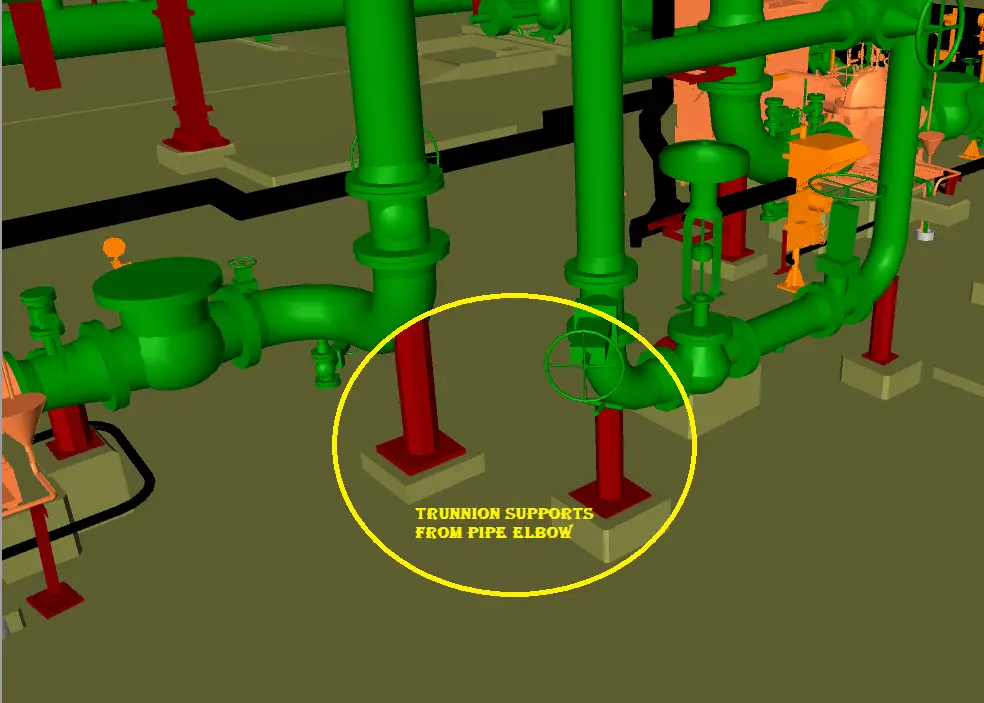
Wide application of trunnion or dummy supports is found in control valve assemblies. In control valve stations, trunnion or dummy supports are usually welded from parent pipe elbows as shown in Fig. 1 below:
Trunnion or dummy supports are quite common to use as adjustable supports on a pump or other rotary equipment for alignment purposes.
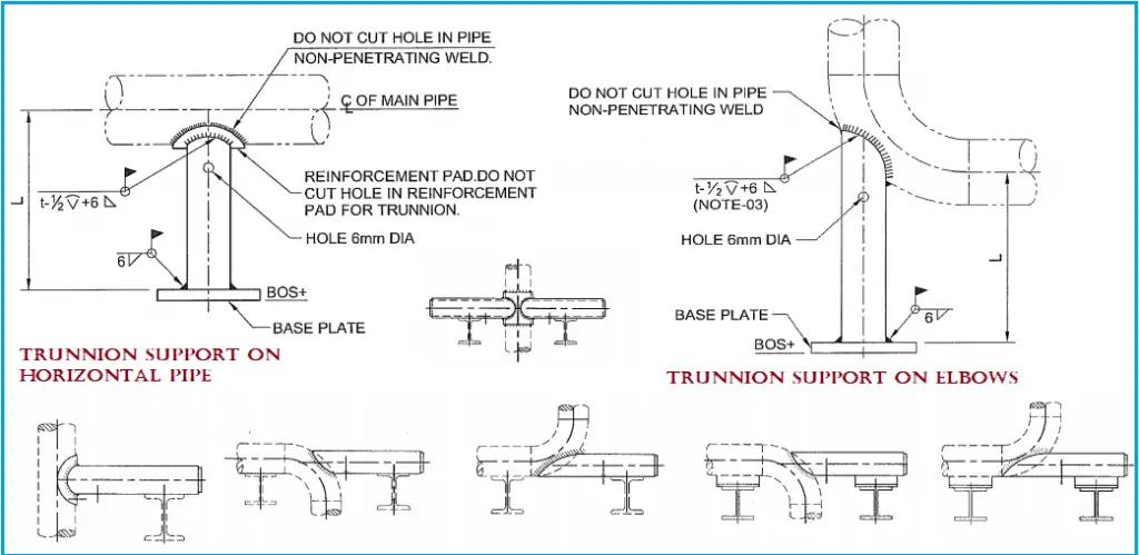
Typical Trunnion Support Configurations
A variety of support configurations can be made by welding trunnion supports on pipes. Examples of some widely used typical pipe trunnion support configurations are provided in Fig. 2:
Trunnion Calculation Method
There are various ways in which trunnion checking can be done. However, the Kellogg Method of trunnion checking using an Excel spreadsheet is the most common among EPC organizations. In some organizations, trunnion checking by the WRC method is prevalent. In recent times, Trunnion or dummy support checking using FEA calculations has been increasing among EPC organizations. Various extended modules of stress analysis programs like FE-Pipe/ FE-bend or other FEA programs are used to calculate stresses in the junction point and check if those are acceptable.
In the next paragraphs, I will brief the steps and formulas used while trunnion checking using the Kellogg method.
Inputs Required for Pipe Trunnion Calculation
The inputs that will be required for pipe trunnion calculation are:
- Pipe Support loads from stress analysis software.
- Parent pipe OD and thickness.
- Pipe trunnion OD and thickness.
- Parent pipe corrosion allowance.
- Parent Pipe material to get stress values.
- Pipe design temperature and pressure.
- Pipe trunnion height.
- RF pad thickness if required/provided.
Steps for Trunnion Calculation by the Kellogg Method
1. First of all run the static analysis in Caesar II/AutoPipe/Rohr II/Start-Prof/Caepipe/Other Pipe Stress Analysis Software to obtain the load values at trunnion nodes from the output processor. It is better to practice taking the maximum value from all load cases (Sustained, operating, design, upset, hydro test, occasional, etc.)
2. After that, calculate the bending stress generated on the pipe shell based on the following Kellogg equation:
Sb=(1.17 * f * √R )/ (t1.5) ……(1)
Here,
- Sb=bending stress in pipe shell
- R=Outside radius of pipe shell
- t=Corroded pipe thickness (actual pipe thickness-corrosion allowance) plus the thickness of reinforcement pad
- f=loading per unit length
3. Now from piping stress analysis software, we will get three forces with respect to each trunnion; longitudinal forces, circumferential forces, and axial forces. So accordingly we will have to calculate three f values as mentioned below:
- Loading due to longitudinal bending, fL=ML/ (Π r2 ) ……(2)
- Loading due to circumferential bending, fC=MC/ (Π r2 ) ……..(3) and
- Loading due to axial force, fA=P/ (2Π r)………..(4)
Where,
- ML=Longitudinal force obtained from Caesar * trunnion effective length
- MC=Circumferential force obtained from Caesar output * trunnion effective length
- P=direct axial force obtained from Caesar II output. and r=outside radius of the trunnion.
4. Next step is to calculate all bending stresses using equation (1) for longitudinal (SL), axial (SA), and circumferential (SC) forces as calculated from equations (2), (3), and (4).
5. Now Calculate longitudinal Pressure Stress (SLP=PD/4t) and Hoop Stress (SCP=PD/2t).
6. In the next step, combine all these forces for proper load cases as shown below and compare the combined value with the allowable stress value provided in terms of the Sh and Sc values as defined in the ASME B31.3 code.
- SL+ SA + SLP <= k * Sh
- SC+ SA + SCP <= k*Sh And
- Trunnion Stress<=Sh
Here trunnion stresses should be calculated as=[{32*Trunnion OD*√(ML2+MC2)} / {Π*(Trunnion OD4-Trunnion ID4)}]
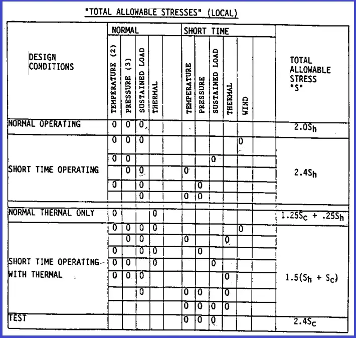
The values of “k” are dependent on loading types. The allowable stress values as suggested in the Kellogg Method are produced below in Fig. 3 for reference.
Options to reduce stresses while Trunnion Support Checking
There are various ways by which the calculated stresses on the trunnions can be reduced so that the dummy calculation qualifies with respect to allowable stresses. Some of such tips are
- While checking trunnions or dummies, it is found that a major chunk of trunnion supports fails due to circumferential loads. So, orient or place the trunnion in such a way that the circumferential force on the trunnion becomes very less to permit/allow greater trunnion heights.
- Reducing the trunnion height or increasing the trunnion size also will reduce the calculated stresses.
- RF pads are required to be added to increase the junction thickness and thereby increase load-carrying capabilities which decrease stresses.
- Increasing the parent pipe diameter will also qualify the trunnions. However, increasing parent pipe size needs process confirmation.
What is the difference between a Trunnion and a Dummy Leg?
Even though the terms “Trunnion” and “Dummy Leg” are used interchangeably, there is a slight difference between the two pipe supports.
Dummy pipe is welded onto the pipe elbow to extend the line to reach the next support while Pipe trunnions are welded to vertical lines. Usually, two short pipe pieces are welded to vertical pipe for better stability for trunnion application. It’s easier to provide an RF pad on trunnion supports but the same is difficult for dummy legs as the pipe profiling and welding at pipe elbows are usually difficult.
Online Course on Pipe Support Engineering
If you want to learn more details about pipe support engineering then the following online course is a must for you:
Hi Anup,
The articles are very usefull to all Piping engineers. Every one uses trunnions for supporting the piping.
I am stuckup with one problem on How to calculate temperature for Trunnion support Or Shoe support?
Generally we ambient temp. for modelling trunnion in CAESAR. But i am looking for article on how to calculate trunnion element OR shoe element temperature. Please provide your valuable details on it. Can we use Skirt temp calculation for calculating the trunnion temperature?
Thanks & Regards..
Prakash Mahajan.
Jacobs Engineering India Pvt. Ltd.
The best method for calculating trunnion/shoe temperature is performing an FEA analysis to get realistic results.
For approximate methods normally process piping people use 40 degree centigrade of temperature drop per inch (25 mm) of length in case of non insulated trunnion/shoe (part outside insulation) and 4 degree centigrade drop per inch inside insulation.
Anyway i will try to find out more on this topic.
Dear Prakash,
Can u please send me the ‘ Skirt temp calculation ‘ method ?
I want it for Distillation column piping Analysis in CAESAR II.
Your reply in this regard is highly appreciated.
Dear Prakash,
Can u please send me the ‘ Skirt temp calculation ‘ method ?
I want it for Distillation column piping Analysis in CAESAR II.
Your reply in this regard is highly appreciated.
Hi Anup, Please clarify below point please. 1)The last formula “as=[{32*Trunnion OD*√(ML2+MC2)} / {Π*(Trunnion OD4-Trunnion ID4)}]” is not relevant to MW Kellogg.
2)As looking at this formula’ s unit, we found out N/mm3 and it is not a stress unit.
Regards
Han
Dear HAN,
Stress in Trunnion is as per Flexural Stress Formula S=Mc/I ,
where:
M=combined moment (ML^2+MC^2)^0.5
c=distance from centroidal axis to outside fiber(OD/2)
I=moment of inertia about the centroidal axis (pi x (OD^4-ID^4)/64.
The outcome unit would be N/m^2 which is a unit of stress.
i’m very thankful to ur such informative topics. i used to visit this site daily and gaining knowledge a lot. keep on educating me like beginners.
I HAVE USED PRG FEA and found SIF 2.1 to be on conservative side. Should not we use it instead.
yes you can use that
I have a question about allowable stress.
Your guide is as below.
SL+ SA + SLP <= 1.5 * Sh
SC+ SA + SCP <= 1.5*Sh
And Trunnion Stress<=Sh,
But Table B-"Total allowable stresses" in the Design manual – Piping Mechanical by The M.W.Kellogg, I can choose total allowable stress according to the design conditions and any cases.
Normal operating – 2.0Sh
Short time operating – 2.4Sh
Normal thermal only – 1.25Sc + 0.25Sh
Short time operating with thermal – 1.5(Sc+Sh)
Test – 2.4Sc
What is different your guide and design manual?
Dear Sir,
thanks for your usefull text
In our Organization we set the unreinforced SIF for intersection point of parent pipe & trunion and model the trunion
then we check the stress at this point at sustain and expansion load case and compare with allowable stress of material.
in your opinion is this true?
so why whould we use the kellog method?
I have come across an excel sheet for Trunnion Strength Calculation which is as per Kellogg’s method. It has 4 case study methods defined which are transit, 200 year, 10000year and blast, based on these types allowable stress changes. Please let me know which one I should pick for onshore O &G Piping.
I have the same question as Jack,
Why “Normal industry practice is to take 1.5 times Sh value as the allowable stress value” instead of using 2,0Sh for normal operation and 2,4Sh for occasional, as MW Kellogg say?
Regards
Hi Need some clarification, If i relate all parameters.
1. Did not see the Sb=(1.17 * f * √R )/ (t^1.5) ……(1) is compared with allowable and used in acceptance criteria
2. Parent Pipe OD or ID is not appearing anywhere in formulation, Does it means any pipe size there is no relation and effect of parent pipe, unless it affects dimension interfence
Hello All,
My question is on piping designer aspect.
Can we have trunnion support on 3D/5D bends?
As wall thickness will be different from Pipe bends & forged elbows does its advisable for critical piping?
If the trunnion is welded to the base then the attached parent pipe wall also experience moments. Hence stresses due to external moment also need to be added. This has not been mentioned in this topic.
Please . Is there any practice we axle document to calculate the dummy stress.
Please any calculation sheet for this issu?
I have a condition to check stress to be within 0.5 hoop stress or else add a reinforcing pad but do not know how to check stresses against hoop since we are calculating bending stresses?
In trunnion check our client has condition of stresses need to be within 50% of hoop stress or else we need to add reinforcing pad. My question is how can I check stresses against hoop stress for trunnion?
Hi Anup,
thanks for the good blog for the trunnions.
I have one query.
In our project, we are having the trunnion pipe supported to vertical pipe from the side along with structural steel.
how to calculate the stresses on the parnet pipe when we take this kind of trunion support?
Hi Anup,
Thanks for your good blog.
I have one query for weld re-pad on trunnion.
Do need to cut hole in reinforcement pad and stub in weld?
Hello Anup Kumar Dey,
I would like to ask the reference of Fig. 3: Allowable Stress Values for Trunnion Calculation as per Kellogg Method. I have one from the M.W. KELLOGG COMPANY, DESIGN MANUAL – PIPING MECHANICAL, SUBJECT 3810 and there is a limitation of TOTAL ALLOWABLE STRESS “S” by 30000 psi. But the table in FIG. 3 looks it doesn’t.