
What is Surge in Liquid HC P/L?
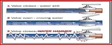
Its commonly called “Water Hammer”, and is defined as a sudden increase in pressure due to an instantaneous conversion of momentum to pressure when flowing liquid stops quickly.
Hydraulic surge is often caused by the transformation of kinetic energy to potential energy as a stream of fluid is suddenly stopped.
Once the pump tripped, you will observe that the pressure in the immediate discharge is decreasing because the flow still going forward with no current supply and a strong wave will rush back towards the pump discharge coming all the way from the close endpoint creating the pressure spike.
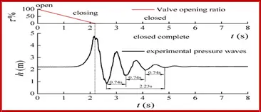
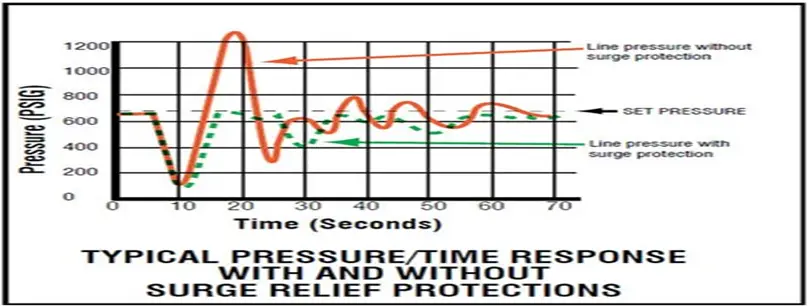
As noticed in the below graph, pressure spikes will continue hitting the pipe/pipeline trying to release the generated excessive energy and therefore your system will be at risk.
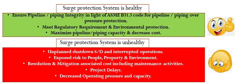
ASME B31.3 defined that the pressure rise due to surge and other normal operation variations shall not exceed the internal design pressure at any point in the piping system and equipment by more than 33%.
Here you have to ask yourself, Do I Have a Safe & Reliable System to Operate?!!!
Why Surge could happen?
- Pumps stoppage/trip / Priming.
- Spurious Closure of manual valves, MOVs (Motor Operated Valves), or an automatic emergency shutdown device – ESD.
- Blackouts / Power failure.
- Slamming shut off a non-return (check) valve.
All of the above will generate pressure waves that travel both upstream and downstream from point of origin.
Please note that some pipelines are in transient operations over 75% of the time.
Surge (pressure rise) increases as much as the pipeline segment length increases since the contained momentum will be higher (more volume).
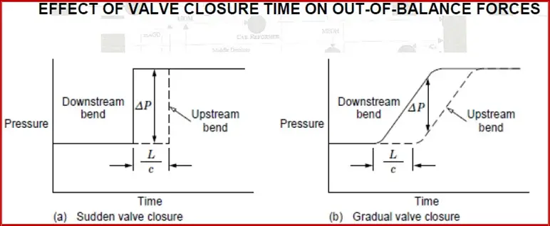
A pressure surge can consist of multiple events, resulting in up to ten times the normal pipeline pressure. When a surge relief valve opens, it vents the pressure to a safety system. Also, it is worth mentioning that Surge pressure is created during the last 20% of valve closure.
Other notes about the Water Hammer
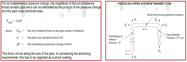
- The rapid closure of a valve can result in an initial reduced pressure downstream which may be sufficient to reduce the absolute pressure below the vapor pressure and generates a cavitation scenario.
- The cavitation might lead to higher transient pressures and unbalanced forces.
- Also, Fast pressurization of a closed system, can double the pressure rise at the far end of the system as the pressure wave is reflected from the closed end.
- This can arise either from the fast opening of a valve at the system inlet or due to pump startup with the pump discharge valve open.
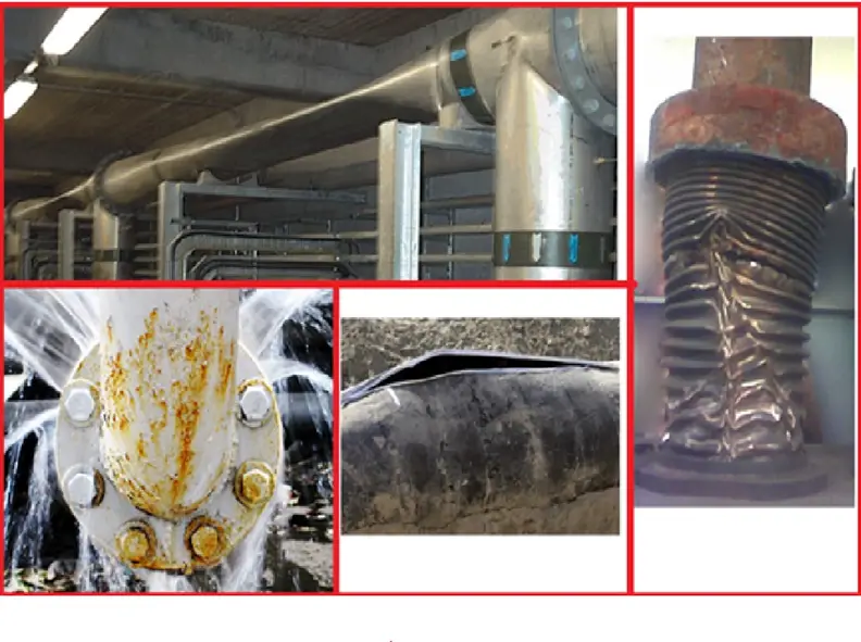
- The surge may result in the creation of huge unbalanced forces within the piping system which may damage the supports, collapse pipe bridges, or even line rupture and displacement from its original location.
- Experiences indicate that the failure of pipework supports as a result of pressure surge is more likely than pipeline rupture due to overpressure.
Challenges of Water Hammer
- Surge can significantly exceed the Maximum Allowable Operating Pressure (MAOP) plus any additional overpressure allowance, typically 33% above MAOP.
- The sudden transition from momentum force (flow) to pressure force will lead to shaking/vibration of pipeline/piping and might lead to severe damage in pipeline/piping if the system design is not adequate.
- Your system could be equipped with a surge relief valve, however, missing calibration and regular checks could lead to failure of the valve to act as required and accordingly lead to destructive failure of the system.
Serious Industrial Incidents due to Lack of Proper Surge Protection
- In 1999, a pressure relief valve failed on a 16-inch gasoline pipeline operated by the Olympic Pipe Line Company in Bellingham, Wash., spilling 277,000 gallons of gasoline into the river. The gasoline exploded, killing three young boys. The incident resulted in five felony convictions for Olympic employees and a $75 million wrongful death settlement.
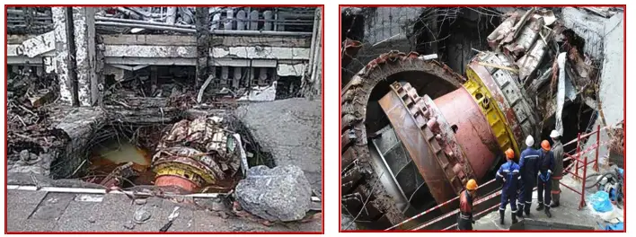
- In 2009, at the Sayano-Shushenskaya hydroelectric plant in Siberia, a severe water hammer ruptured a piping segment going to a turbine due to improper surge relief system design. A transformer exploded, killing 69 people.
Calculation of Water Hammer
A- Manual calculation – Joukowski formula:
- Role of Thumb used in the past to estimate the surge pressure, considering that the only variable is the velocity, P is equal to
0.8 * Weight of liquid per cubic foot * Velocity Change
- Another old way to estimate is to consider a 50 Psi change in pressure with the velocity change of every 10 ft/sec
Can you still use these formulas?
Yes BUT ONLY while you are standing for a quick and rough estimation.
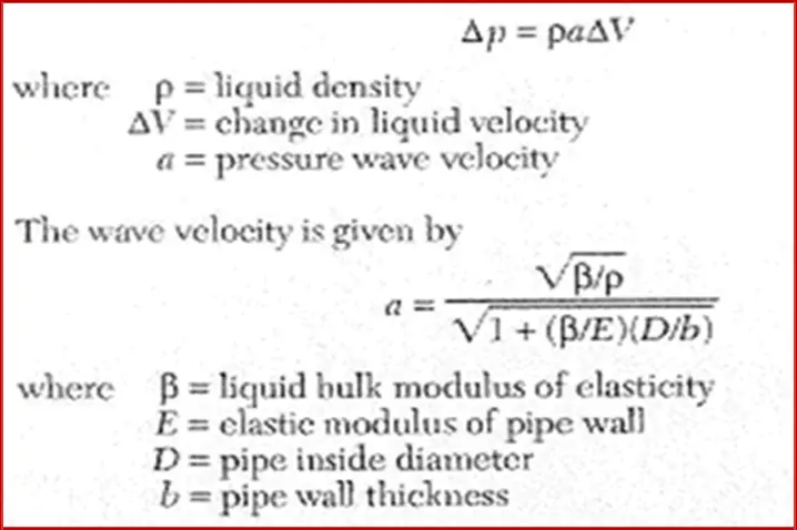
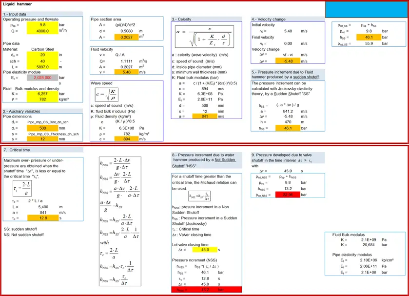
- The Joukowsky equation is a simplified method for calculating the peak transient pressure experienced when a valve is closed against a fluid in motion and may be represented as follows:
ΔP=ρ a Δv
- ρ Liquid Density
- a Pressure Wave Velocity
- Δv Change in Liquid Velocity
- The Joukowsky equation takes into consideration the elasticity of the pipe wall and the compressibility of the fluid itself through the calculation of the speed of sound (a), however, assumes instant closure of the valve.
Manual calculation – Joukowski formula
Required Inputs for Joukowsky Equation:
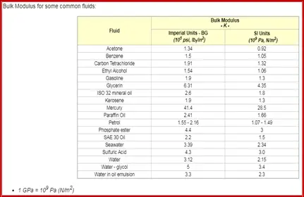
- Fluid Properties: Density, Viscosity, Vapor pressure, Bulk modulus & Temperature.
- Pipe Properties: Roughness, Young Modulus & Poisson ratio.
Explanation of main inputs:
- Bulk modulus: is the property characterizing the compressibility of a fluid, i.e. how easily a unit volume of a fluid can be changed when changing the pressure working upon it.
- The Bulk Modulus Elasticity can be expressed as:
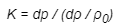
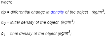
Some fluids have ready-calculated Bulk Modulus Elasticity:
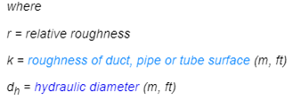
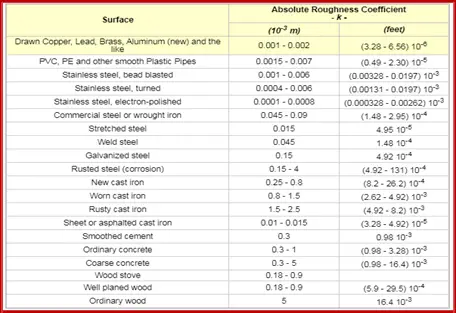
- Relative roughness: Is the ratio between absolute roughness and pipe diameter Relative roughness can be expressed as:

Some pipe material Roughness is available :
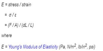
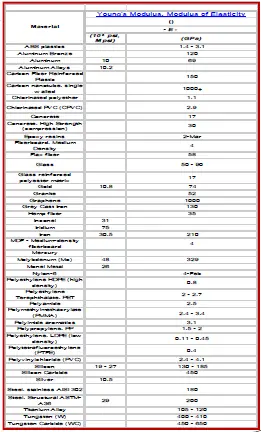
- Young Modulus: is a measure of the stiffness of an elastic material. It is used to describe the elastic properties of pipeline/piping.
- Young’s modulus can be expressed as
Some pipe material’s Young Modulus are available :
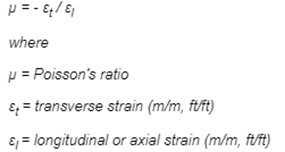
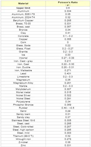
- Poisson ratio: the ratio of the relative contraction strain (transverse, lateral or radial strain) normal to the applied load – to the relative extension strain (or axial strain) in the direction of the applied load
Poisson’s Ratio can be expressed as
Some pipe material Poisson’s ratio is available :
Calculation sheet
Limitations – Joukowsky formula:
- Although the Joukowsky formula is far better and more precious than the past rough estimation formulas, still it can be only applicable to a limited subset of fluid systems.
- Its application should be limited to situations matching the following criteria: Simple ‘linear’ piping systems i.e. there are no branches by which pressure waves can be reflected back and cause constructive interference in the mainline. Valve closure time is significantly shorter than the pressure wave communication time. System frictional losses are similar to that of a water transport system.
- Additionally, the Joukowsky equation does not consider column separation in its analysis of fluid hammer. Column separation can often result in surge pressures exceeding those predicted by the Joukowsky equation and therefore the Joukowsky equation should not be applied when analyzing a system in which the pipeline pressure can rapidly drop below the fluid vapor pressure.
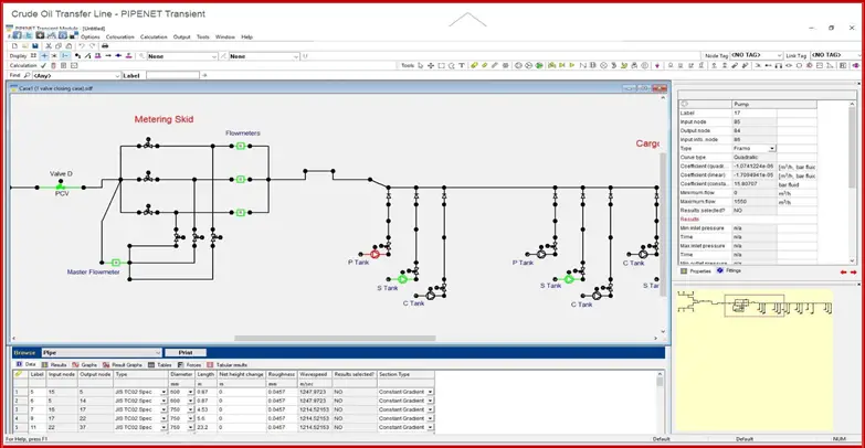
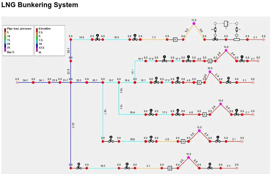
- As a process engineer, you can use it to verify vendor documents or to identify the healthiness of your system, however, for accurate and precise data you need to run PIPENET or similar software to estimate accurately the pressure rise. Then you will be translating this data into generated forces.
- Once you have the generated forces, pick up the phone and call the piping engineer to run CAESAR software which will verify whether the piping/pipeline is granted well-designed supports and structure to make sure that it will not go anywhere else after the surge event occurs.
B- Pressure Transient Assessment using Modelling Software
There are currently various software packages that can be used for analysis such as
- HyTran
- Flowmaster
- WANDA
- Hammer
- AFT Impulse
- PIPENET
- PTRAN
Surge Protection Systems
Initially, we need to agree on the fact that the surge phenomenon is inevitable and therefore we have to identify an optimized option to protect our system with the least associated cost (CAPEX / OPEX). Please refer to our previous article on Optimization @ https://whatispiping.com/process-optimization
Design Consideration of Surge Protection systems:
- The design of a complete surge relief system is dependent upon a complex range of factors, including the potential for pressure increases, the volumes which must be passed by the surge relief equipment in operation, and the capacity of the system to contain pressures.
- Control or ESD valve closure times can also affect surge pressures in a pipeline. By extending valve closure time, a more gradual flow decay can be achieved.
- Control narrative and system interlocks to ensure Staged pump shutdown sequence and linked ship/shore ESDs when your facility is linked to loading berths/jetties.
- Carry out transient/surge analysis using detailed computer modeling to simulate the complex interactions of equipment, pipelines, and fluid to normal, fault, and emergency events.
- Design piping to withstand maximum surge pressure – MSP.
- Although many design approaches can help reduce surge pressures in pipelines, going for a higher pipe rating or massive support arrangements aren’t recommended for an associated significant cost, and a surge relief valve is found to be the most feasible option to protect the system.
- A correctly designed surge relief system will include components to dampen or slow the relief valve on closing, and this often requires sophisticated reverse flow plots.
- In nitrogen-loaded Surge Relief valves, attention must be paid to the nitrogen gas system. The nitrogen system must supply a constant pressure (setpoint) to the modulating valve, even under conditions of varying ambient temperatures. Normally, the system is designed to use standard gas bottles and has its own control system to regulate the nitrogen supply pressure.
Surge Relief Solutions / Devices:
- Ensure Proper design is applied considering the worst-case scenario with its respective control narrative for valve interlocking and proper mitigating means are in place.
- MOVs / ESD Closing time are enough to absorb the wave velocity created by Surge. This can be assured by having a proper Equipment strategy in place which will ensure that Surge relief valves’ set points are verified and the valves are being calibrated on regular basis to ensure that they will be operated whenever required.
- Ensure that operating procedures are in place and operations are well-trained and competent to operate.
- Line design pressure/rating.
- Piping Supports are well designed to withstand the shaking/vibration resulting from Surges.
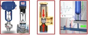
- Surge relief valve and associated relief Drum.
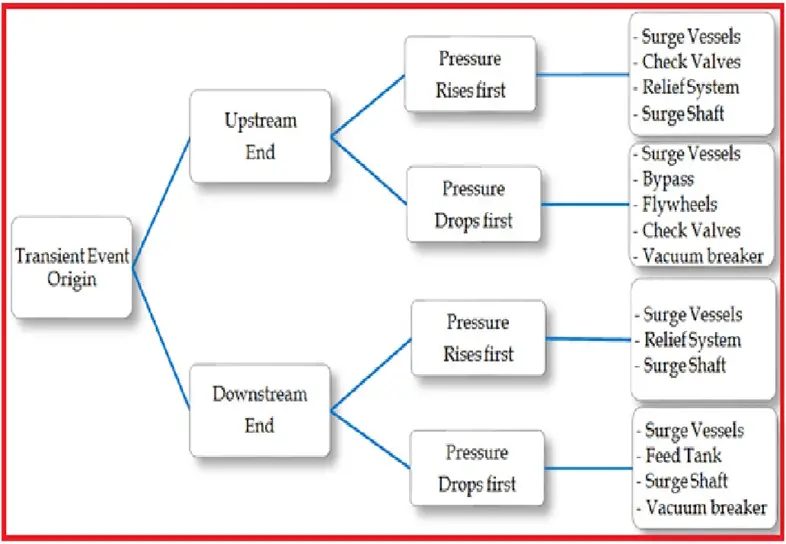
In general, Protection systems can be classified as either Active or Passive:
A- Active Protection
By using devices to actively protect the systems against the effects of pressure surge during pipeline normal operation like:
- Variable speed pumping.
- Soft starters.
- Slow closing and opening valves.
B- Passive Equipment for Surge Protection
- Surge Vessels.
- Surge Shafts.
- Air Valves.
- Vacuum Breakers.
- Pressure Relief Valves.
- Surge Anticipation Valves.
- Intermediate Check valves.
Please note that if there is a shortfall or limitation of this document then it is because of me, while any success or correctness would be solely from the great and generous Allah.
Resources
- ASME B31.4 Pressure Pipeline Code prescribes requirements for the design, materials, construction, assembly, inspection, and testing of piping transporting liquids such as crude oil, condensate, natural gasoline, natural gas liquids, liquefied petroleum gas, liquid alcohol, liquid anhydrous ammonia, and liquid petroleum products between producers’ lease facilities, tank farms, natural-gas processing plants, refineries, stations, ammonia plants, terminals, and other delivery and receiving points.
- API RP 520, ‘Sizing, Selection, and Installation of Pressure-Relieving Devices in Refineries, Part 1 – Sizing and Selection’, Seventh Edition, January 2000.
- API RP 521, ‘Guide for Pressure-Relieving and Depressurizing Systems’ Fourth Edition, March 1997.
- CRR 136/1998, Workbook for Chemical Reactor Relief Sizing, HSE.
- DIERs Manual ” A perspective on Emergency relief system” by DIER Technical Committee. Guide to Pressure Relief (PSG 8), Part C: Section 5, 1999.
- Chemical Engineer’s Handbook – Perry, Seventh Edition
- “Investigation Report: Refinery Explosion and Fire,” U.S. Chemical Safety and Hazard Investigation Board, March 2007.
- “Olympic Pipe Line accident in Bellingham kills three youths on June 10, 1999,” History.org.
- “Lessons from Russian Hydroelectric Plant Accident,” Engineering Ethics Blog.
- “An Introduction to Liquid Pipeline Surge Relief,” Emerson Process Management, April 2007, page 2.
Want to know more!!! Kindly refer to the following:
Introduction to Pressure Surge Analysis (With PDF)
Understanding Centrifugal Compressor Surge and Control
Water Hammer Basics in Pumps for beginners
Pipe Stress Analysis from Water Hammer Loads
Dear,
Calculation sheet, Where can you download the link?
Thank you
Pedro