
Glass Reinforced Epoxy Piping or GRE pipes are becoming a popular choice in the piping and pipeline industry due to their many advantages. The present article aims to give some basic principles and cares to be considered at the moment of the draft design of an aboveground GRE pipeline.
GRE pipe and GRP pipe differ in the used resin during bonding the glass fiber. GRE pipe used Epoxy Resin while GRP pipe used Isophthalic Resin. The designer should evaluate if a deeper stress and strain analysis is required for the pipeline, for the supports, and for other bearing structures connected to the pipeline.
Apart from special cases, GRE pipes should be always connected to the bearing structures by means of saddles, made of steel or concrete or of other materials (GRE itself for instance), in order to distribute the loads on a length and on an angle that is able to minimize the stress concentration on the pipe/support contact points.
In nearly all aboveground applications tensile resistant couplings should be used.
Only in the case of well-supported pipelines for non-pressure applications, a non-tensile-resistant system can be used. The forces close to elbows or other singular points such as valves, reducers, or tees, can become relevant.
GRE/GRP Pressure Class Selection
The selection of the GRE pressure class has to be made according to the following loads:
- working pressure
- surge pressure (water hammer)
- spacing of supports
- thermal load
The stress in the hoop direction due to the internal pressure is calculated as shown in Fig. 1:
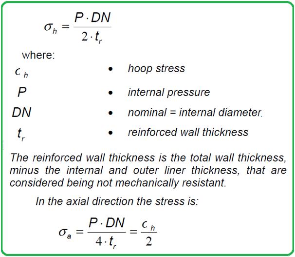
- In GRE pipes it is important to always check the axial stress due to internal pressure since the material is anisotropic and the difference of strength in the hoop and axial direction is relevant.
- The sum of stresses due to the above loads, calculated in the hoop and axial direction, has to be lower than the allowable stresses, defined for each pipe class or by a specific job.
- Approximate values for allowable stresses for a common filament wound pipe for above-ground use are 50 Mpa in the hoop direction and 30 MPa in the axial direction.
- The high working temperature could reduce the allowable stress in the GRP pipe and consequently reduce the pressure class.
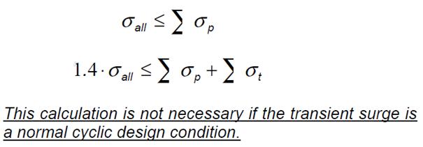
- The Code (AWWA M45) generally considers a 40% tolerance in the allowable stresses in case of transient surge pressure based on the increased strength of fiberglass pipes for rapid strain rates.
Both the following equations (Fig. 2) have to be calculated:
Vacuum Design for GRE pipes
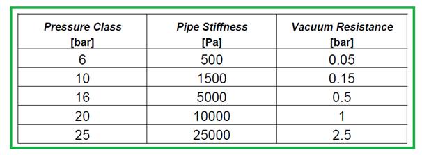
The AWWA M45 standards admit a safety factor for vacuum conditions between 1.3 and 3.
For different pressure classes and the same standard pipe (55° filament winding), the approximate relation between pressure class, stiffness, and vacuum resistance is resumed in the following table (Fig. 3).
For low-pressure pipes with a vacuum, a convenient solution can be either to provide stiffening ribs or a sandwich pipe wall structure with a mortared core.
Thermal Expansion Coefficient of GRE Pipes
The approximate axial coefficient of thermal expansion (α) for a GRP pipe made by filament winding with a winding angle of 55°is:
α = 1.8×10⁻⁵ m/m °C
For different GRP pipe classes (with mortar core) or for different winding angles, please consult the GRP Vendor.
The total expansion (or contraction) of a pipe length ( L ) is calculated as:
ΔL =α ⋅ L ⋅ ΔT
ΔT is the temperature gradient (positive or negative) with reference to the installation temperature T0.
The thermal expansion coefficient of GRP has the same magnitude as the steel coefficient (α=1.2× 10⁻⁵ °C-1), whilst thermal end loads for restrained expansion are significantly lower since the axial E-modulus of GRP (Ea) is around 1/20th of steels.
The loads applied to expansion joints and to bearing structures are hence considerably lower in GRP pipelines.
Thermal End Loads for GRE pipes
The thermal end load (F) due to constrained expansion is calculated as shown in Fig. 4:
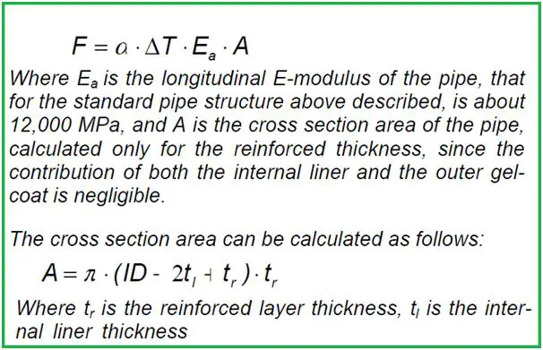
and ID is the internal (nominal) diameter.
The thermal end load due to constrained expansion could be too big for both the stress arising in the pipe and for the load that the bearing structures have to support.
Considering the pipe itself, its elastic stability has to be checked. The pipe’s elastic stability depends on the pipe section, on the E-modulus, and on the span between axial guide supports which is the length of free deflection.
The allowable compressive end load due to instability (Pcr) is calculated as shown in Fig. 5:
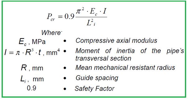
When the end loads are too big, they should be reduced by providing the system with anchor points and expansion joints, or better, by operating on the pipeline’s geometry and on the support placement in order to let the line expand where it is not dangerous. Expansion loops can be added to the system where it is possible.
The second solution is preferable since the involved loads and thrusts are much lower than in a similar steel pipeline.
Selection of Anchor Points in GRE Pipeline
Pipe Anchors have to be placed in such a way that pipeline expansions are forced in predetermined directions, in order to balance loads and displacements on the different expansion devices, and to minimize displacements close to dangerous locations, for example in weak branch connections or in connections that are not allowed to move.
Use of Directional Changes or Offsets in GRE Piping
Changes of direction in a pipeline can be used to partially absorb the line’s elongation, when close to an elbow; a branch that is free to expand is available, as shown in the following figure (Fig. 6):
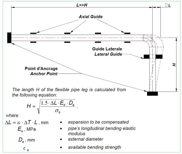
The “available bending strength” is considered the remaining strength, after that, all of the other stresses on the pipe have been removed, such as the stresses due to internal pressure.
Clearly, any term of the equation can be obtained once all of the other terms are known, for instance, the length ΔL that can be absorbed can be found when the length of the leg that is available is H.
Expansion Loops for Long GRE Pipelines
“U” expansion loops are provided for long straight pipeline runs, as shown in the figure (Fig. 7) below:
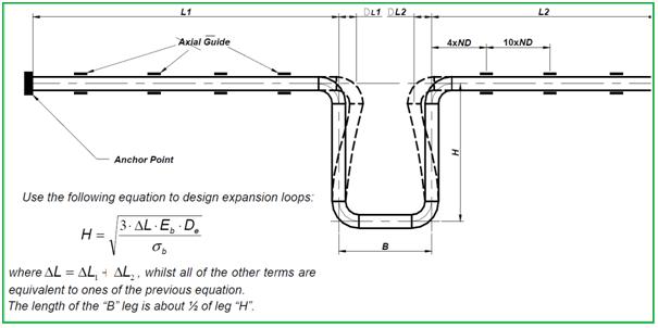
The recommended spacing between axial guide supports close to the expansion loop is also shown in the drawing. Other supports shall be spaced following other calculations (beam load).
Use of Expansion Joints in GRE Piping Systems
Various kinds of standard expansion joints can be used. Low-stiffness expansion joints are preferable since they develop a low reaction in correspondence with relatively big displacements. GRE pipes expand more than steel pipes but have much lower thrusts.
Using stiff expansion joints would reduce the stresses in the pipe only by a little
We suggest rubber joints with one or more waves, possibly with limiting travel devices, with an activation load lower than the Pcr load, and with a working travel equal to the total expansion.
Support Span for GRE Pipes
Horizontal pipes should be supported according to the spacing suggested by the support spacing data or according to a specific project.
A pipe support span is defined as the distance between two consecutive pipe supports or anchoring devices.
The maximum support span/spacing length for every pipe size and class is suggested by the Technical Department of GRP Vendor for standard pipes or according to a specific project.
The span length is limited by the following considerations:
- the maximum axial strain must not exceed the allowable value;
- the mid-span deflection has to be smaller than 1/300th of the span length and anyway not exceed 15 mm which is the minimum value.
If factor (b) is the determinant factor, then the distance between supports must not be changed by reducing the working pressure.
Often the spacing between the supports is set by other reasons, for instance, joint spacing or existing bearing structures. Normally the 6-meter half-length span is the maximum that is used, even for large-diameter pipe, for which a theoretical longer span could be used. The maximum support span in meters is shown in the following table (Fig. 8), for different pipe sizes and pressure classes:
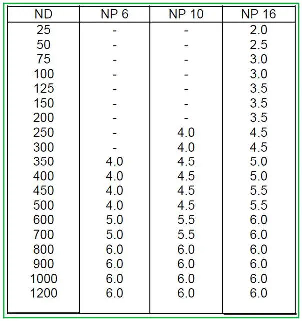
The maximum span has to be evaluated for a continuous span length when the joint can transmit axial loads.
GRE Piping Support Design Rules
The following are suggested basic rules for design and for the positioning of supports, anchors, and guides.
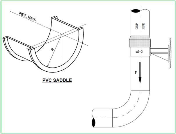
Loads with linear and punctiform contacts have to be avoided, therefore curved supports that bear at least 120 degrees of the bottom part of the pipe and that have maximum bearing stress of 600 kPa have to be used. Unprotected pipes are not allowed to press against roller supports or flat supports. Do not bear any pipe directly against ridges or other points of the support’s surface. Protective sleeves have to be used in these cases.
To protect pipes against external abrasion between the pipe and the steel collar, a PVC saddle (Fig. 9) or a protective rubber layer has to be positioned in between. The PVC saddle is necessary when free axial sliding of the pipe must be permitted (axial guides).
Valves and other heavy equipment must be supported independently in both horizontal and vertical directions.
The pipe clamps must fit firmly but must not transfer excessive force to the pipe wall. This could result in deformations and excessive wall stresses
Vertical runs have to be supported as shown in Fig. 9. Excessive loading in vertical runs has to be avoided. It is preferable to design a “pipe in compression” than a“ pipe in tension”. If the “pipe in tension” method cannot be avoided, take care to limit the tensile loading below the maximum tensile rate recommended for the pipe. The guiding collars will have to be installed by using the same space intervals used for horizontal supports.
Anchoring Points in GRE Piping Installations
An anchoring point must efficiently restrain the movement of the pipe against all of the applied forces. Anchors can be installed in both horizontal and vertical directions. Pipe anchors divide a pipe system into two sections and must be attached to some structure that is capable of withstanding the applied forces. In some cases pumps, tanks, and other similar equipment function as anchors.
However, most installations require additional anchors where pipe sizes change or where fiberglass pipes join another material or a product from another manufacturer. Additional anchors are usually located on valves, pipeline changes of direction, and major branch connections.
It is a good practice to anchor long, straight runs of aboveground piping at intervals of approximately 90 m.
In any case, the correct positioning of anchor points has to be decided only after a detailed stress analysis.
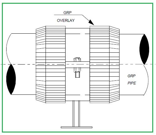
The pipe must be able to expand radially within the pipe clamps.
To secure the pipe to the clamp it is suggested to apply a GRP lamination (as shown in Fig. 10 below) on each side of the clamp. If the movement of the pipe has to be restrained only in one direction, it is sufficient to apply only one overlay ring of GRP in the opposite position.
FAQs for GRE Piping Systems
What is GRE piping?
GRE stands for Glass Reinforced Epoxy. It is a composite material used for manufacturing pipes and fittings. GRE piping systems are known for their corrosion resistance and durability.
What are the advantages of using GRE piping systems?
GRE piping systems offer several advantages, including excellent corrosion resistance, high strength-to-weight ratio, low maintenance requirements, high hydraulic efficiency, and a long service life. They are also lightweight and easy to install.
Where are GRE piping systems commonly used?
GRE piping systems are used in a wide range of industries, including chemical processing, offshore oil and gas, plant piping, oil and gas flowlines, water treatment, power generation, downhole tubing and casing, irrigation, and desalination plants.
How does GRE piping compare to other materials like steel or PVC?
GRE piping is corrosion-resistant, making it an excellent choice for environments with corrosive substances. It is lighter than steel, making installation easier, and it doesn’t require painting or coating. PVC is also corrosion-resistant but may not be suitable for high-temperature applications or certain chemical environments.
What is the temperature and pressure rating of GRE piping systems?
The temperature and pressure ratings of GRE piping systems can vary depending on the specific material and design. Generally, they can handle temperatures up to 250°F (121°C) and pressures up to 1500 psi (10,342 kPa).
Can GRE piping systems be used for underground applications?
Yes, GRE piping systems can be used for underground applications. They are resistant to soil corrosion and can be designed to meet the specific requirements of buried installations.
Are GRE piping systems environmentally friendly?
GRE piping systems are considered environmentally friendly because they are corrosion-resistant, reducing the risk of leaks and spills that can harm the environment. Additionally, they have a long service life, reducing the need for frequent replacements.
How are GRE pipes joined together?
GRE pipes are typically joined using adhesive bonding or flange connections. Adhesive bonding involves using epoxy resin to bond pipe sections together, creating a strong and leak-proof joint. Flange connections are used for larger pipe sizes and provide a more mechanical connection.
What maintenance is required for GRE piping systems?
GRE piping systems require minimal maintenance. Regular inspections for signs of damage or wear are recommended. In most cases, maintenance involves cleaning and visual inspections.
Can GRE piping systems be customized for specific applications?
Yes, GRE piping systems can be customized to meet the specific requirements of different applications. They can be designed to handle various chemical fluids, temperatures, pressures, and sizes.
Are GRE piping systems cost-effective?
While GRE piping systems have a higher initial cost compared to some materials, their long service life, low maintenance requirements, and corrosion resistance can make them cost-effective over the long term.
Are there any limitations to using GRE piping systems?
GRE piping systems are not suitable for extremely high-temperature applications or applications where fire resistance is critical. It’s important to consult the manufacturer to ensure the system meets the specific needs of the project.
What are the Design Codes for GRE Piping Systems?
Design codes and standards for GRE (Glass Reinforced Epoxy) piping systems may vary depending on the specific application and location of the project. The most widely used GRE piping codes are:
- ISO-14692
- NORSOK M-710
- DNV GL RP-F112
- AWWA M45
Few more related Resources for you..
HYDROSTATIC FIELD TEST of GRP / GRE lines
Stress Analysis of GRP / GRE / FRP piping system using Caesar II
A short article on GRP Pipe for beginners
Stress Analysis of GRP / GRE / FRP Piping using START-PROF
We thank you for all the efforts you have made to energize the pipe industry.
Hi Anup,
This simple but very informative write up has been so helpful to me, as a novice in GRP piping.
Thank you so much. Love the fundamentals here and how it relates to applications. Used it for reference in a technical paper write up promoting GRP pipes as an alternative to metallic.
Dear Dev,
I have no words to appreciate the presentation.
This is unique. Appreciate your efforts to educate others and help them to do a good job.
s very informative .pls can sugesst friction force to taken for GRP pipes on sterling steel piperacks and anchor force.water supply works.guide force.
Hi and thank you,
Can u please indicate a reference of vacuum vs stiffness (like the table u have provided in your passage)
Hi Boss
All your notes related to GRE Pipes are very useful
Please update regarding notes of UPVC, PPH, PVC-C and RTR UG Piping Pipes for Construction . It will be more helpful
Hi Dey,
Thank you for your hard work