What is Corrosion Under Insulation (CUI)?
The Corrosion Under Insulation (CUI) war has been fought for many years in the chemical and petrochemical industry. Corrosion Under Insulation is severe localized corrosion damage that is caused by the moisture (intruding water) present on the external surface of insulated equipment. The corrosion processes are well understood, yet corrosion under insulation or CUI often goes undetected until the damage is significant, which may lead to catastrophic failures, e.g., on equipment operating under high pressure. The industries that are highly impacted by CUI are
- Refineries
- Chemical industries
- Petrochemical industries
- Offshore industries and
- Marine and Maritime industries
Materials Prone to CUI
Corrosion under Insulation may occur on:
- Carbon steel (general/localized corrosion)
- Stainless steel (localized corrosion/stress corrosion cracking)
- Alloy Steel
Effect of Corrosion Under Insulation
CUI (Corrosion under insulation) cost studies have shown that:
- 40 to 60 % of pipe maintenance costs are caused by CUI
- NDE/inspection costs with a high confidence level for detecting CUI are equal to or exceed field painting costs
- Approximately 10 % of the total maintenance budget is spent repairing damage from Corrosion under insulation or CUl
If corrosion under insulation is not detected in the proper time, it can lead to failures like explosions, leaks, downtime, equipment failure, etc. The major risks and effects of CUI can be summarized as follows:
Structural Integrity Loss: Weakening of pipes, vessels,
equipment
- Increased Maintenance: Costly and frequent repairs for hidden damage
- Safety Hazards: Potential leaks, ruptures, or fire risks
- Production Downtime: Repairs lead to shutdowns and delays
- Environmental Impact: Risk of hazardous spills affecting surroundings
Corrosion Under Insulation Temperature Range
General temperature ranges in which the risk of Corrosion Under Insulation is prevalent are
- Carbon steel: -4 °C to + 175 °C: Risk of CUI (highest risk area: +60 °C to +120 °C)
- Stainless steel: +50 °C to +175 °C
- Insulation of process equipment is normally implemented when the outer steel temperature exceeds 50 °C (due to the risk of work-related injuries as well as heat loss).
Mechanism of Corrosion Under Insulation
CUI involves the requirement of the following three elements:
- Availability of oxygen.
- High temperature.
- The concentration of dissolved species.
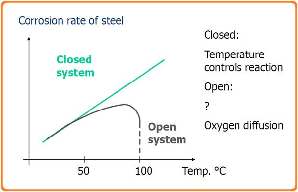
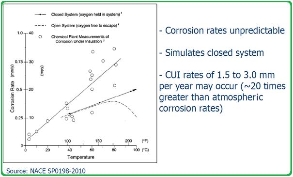
In general, as temperature increases, the corrosion rate reduces as the amount of dissolved oxygen decreases. But when the surface is covered by insulation, moisture makes it a closed system and retains the dissolved oxygen. In some cases, chlorides and acids may be present in the insulation, which greatly promotes corrosion of the underlying surface in the presence of moisture.
For oxygen corrosion to happen, there needs to be some water or moisture on the steel surface. Water usually gets in through cracks or damage in the insulation jacket, which can happen because of poor installation, wear and tear over time, or damage during use. The water typically comes from rain, deluge systems, spills from operations, leaking steam lines, or condensation from humid environments. Depending on the insulation’s ability to absorb water and the temperature of the component, water might stick around. Sometimes, if the conditions are right, the insulation might stay wet and never fully dry out. CUI (Corrosion Under Insulation) can usually be broken down into four types:
- Low temperature (like cryogenic or super-cold conditions)
- Sweating service (when the temperature is below the dew point)
- High temperature
- Cyclic temperature (when temperatures go up and down)
For CUI to happen, there need to be four things: an anode, a cathode, an electrolyte, and a way for electricity to flow between them.
In simple terms, the electrolyte in CUI is oxygenated water, which might have contaminants that can speed up the corrosion process.
Let’s look at how this works in practice on a pipe or pressure vessel with thermal insulation. Once water gets past the insulation, it either gets absorbed or trapped. When the water touches the hot steel, it evaporates. This vapor then moves through the insulation to the cooler outer jacket or barrier, where it condenses. The water that condenses then moves back toward the hot steel, and the cycle repeats. Because of this cycle of evaporation and condensation, contaminants can build up on the steel surface. These contaminants can damage the steel’s coating and eventually lead to CUI. This cycle can also damage the insulation, making it less effective. Insulation that holds less water and dries out faster is usually better at resisting CUI damage. Also, keeping the insulation jacket intact and the steel’s external coating in good condition are key factors in reducing CUI risk. Fig. 1 below shows a typical schematic of the CUI process.

Factors Affecting Corrosion Under Insulation
The major factors that affect the corrosion process under insulation (CUI) damage are:
- Frequency and duration of the moisture exposure
- Service temperature.
- Types of insulation and protective barrier conditions.
- Cyclic operation modes.
- Corrosivity of the environment
- Type of climate where the system is installed.
- Proximity to humidity-causing equipment like cooling towers, etc
Damage Methodology in Corrosion Under Insulation (CUI)
CUI on carbon and low-alloy steels typically results in localized corrosion or pitting, though in severe cases, the damage can be widespread. This form of corrosion happens when moisture and oxygen are present, causing damage when water gets trapped under the insulation and comes in contact with the exposed steel. For these steels, CUI usually occurs at operating temperatures between 10°F (–12°C) and 350°F (175°C).
When insulation is removed, the damage often shows up as a loose, flaky scale on the corroded component. In some cases, the corrosion looks like carbuncle-type pitting, often found under a failed paint or coating. Localized CUI can cause pin-hole leaks, and in extreme cases, it can weaken the structure or pressure capacity of the equipment, potentially leading to a plastic collapse. As the temperature of the metal increases, corrosion rates tend to rise—up to the point where the water evaporates quickly. For insulated components, corrosion is typically worse when metal temperatures are between 212°F (100°C) and 350°F (175°C), because water doesn’t vaporize as easily, and the insulation remains wet.
The severity and rate of corrosion in pressure equipment due to CUI depend on several factors:
- The wet exposure cycle (how long and how often the component is exposed to moisture)
- The corrosiveness of the water or environment
- Failure of protective barriers, like paint or insulation jackets
There are several controllable factors that influence the likelihood of in-service CUI, including the design of the equipment, the choice of insulation and external coatings, operating conditions, construction methods, and maintenance or inspection practices.
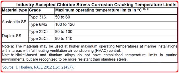
For austenitic and duplex stainless steel components, CUI can lead to Erosion Corrosion Stress Corrosion Cracking (ECSCC). The damage usually appears as surface cracks that spread out in multiple directions, often visible as a craze-cracked pattern on the surface. These cracks can worsen over time and lead to leaks, ductile tearing, or even fractures. Interestingly, the material may not show obvious signs of corrosion. ECSCC occurs when tensile stress (often from weld residual stress), temperature, and an aqueous chloride environment combine. Dissolved oxygen also increases the risk of cracking. The most critical temperature range for ECSCC is between 140°F (60°C) and 400°F (205°C).
Austenitic stainless steels (like 300-series) are particularly vulnerable to ECSCC, while duplex stainless steels are generally more resistant. Nickel-based alloys tend to offer high resistance, although they’re not completely immune. The amount of nickel in the alloy plays a big role in its overall resistance to ECSCC. Alloys with 8% to 12% nickel are the most susceptible, while those with nickel content above 35% are highly resistant, and alloys with more than 45% nickel are almost immune to ECSCC. On the other hand, carbon steels, low-alloy steels, and 400-series stainless steels are not susceptible to ECSCC.
Corrosion under Insulation of Carbon Steel
Insulated carbon steel corrodes due to:
- Infiltration of water under insulation (rain, process liquids, firewater, etc.)
- Condensation water
- Ingress of external contaminants
The insulation material may also contribute to CUI:
- Creates a crevice for water retention
- May absorb water
- May leach contaminants that increase the corrosion rate
Temperature and oxygen – corrosion rate for CUI
CUI of carbon steel
Corrosion under the insulation of Stainless Steel
Stainless steel (austenitic or duplex) corrodes due to:
- Chlorides (or other halides) in the presence of water are transported to the hot surface
- The chlorides are concentrated by evaporation of the water
- The chloride concentration reaches a critical level, causing stress corrosion cracking (SCC). (The critical chloride concentration depends on Temperature and alloy type.)
- The insulation material may also contribute to CUI in the following ways:
- Creates a crevice for water retention
- May absorb water
- May leach contaminants (e.g. chlorides) that cause ESCC
How is CUI avoided?
By preventing moisture from entering the insulation material and the steel surface, corrosion under insulation can be prevented. These can be achieved by
- Correct selection and design of the insulation material
- Good design of the item to be insulated—e.g. it is difficult to insulate around flanges, taps, flowmeters, supports, etc.
- The cover above the insulated item (against rainfall, etc.).
Application of corrosion protection
On average, 60% of all insulation in service for more than 10 years will contain corrosion-inducing moisture, which will result in corrosion under insulation.
Carbon steel:
The following steps are followed to prevent corrosion under insulation for carbon steel piping/equipment materials.
- Organic coatings
- Thermal-sprayed aluminum (TSA)
- Personnel protecting cages
Stainless steel (austenitic or duplex)
To prevent the CUI of stainless steel materials, the below-mentioned steps are taken:
- Organic coatings
- Thermal-sprayed aluminum (TSA)
- Al-foil wrapping (prevents ESCC and pitting)
- Personnel protecting cages.
Organic coatings on carbon steel
- Experience shows that organic protective coatings on piping in CUI service range from 5-13 years
- Once the protective life is reached, field re-painting is necessary (or periodic NDE in order to monitor CUI).
- Coatings may be damaged during handling and installation – leaving unprotected areas.
- Important parameters for coatings used for CUI prevention: – High permeability resistance (barrier protection) – High flexibility (for cyclic temperature service)
Methods of CUI protection
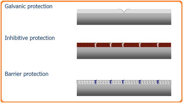
The following image (Fig. 4) shows the methods to prevent various types of corrosion under insulation.
The common ways to prevent CUI are:
- Closed-Cell Insulation: Limits water absorption, reduces risk
- Metal Cladding: Proper sealing and installation block moisture
- Drainage Design: Ensures trapped moisture can escape
- Material Choice: Ensures long-term asset protection
- Sealing Techniques: Properly sealed systems minimize moisture entry
- Protective Coatings: Anti-corrosion coatings on metal surfaces
- Vapor Barriers: Prevents moisture infiltration
- Temperature Control: Reduces condensation and moisture retention
- Preventive Inspections: Scheduled checks to identify potential CUI
- Controlled Environments: Where possible, limiting exposure helps prevent CUI
Thermal Sprayed Aluminium (TSA) to prevent corrosion under insulation
- TSA may provide long-term corrosion protection at significant life cycle cost savings, however at higher initial costs.
- TSA provides atmospheric corrosion protection for more than 40 years.
- Has been recorded to provide 25-30 years of maintenance and inspection-free CUI service.
- Application by electric arc or flame spray.
- It requires high-quality surface preparation and strict application control.
Advantages of TSA in CUI prevention:
- The coating is robust
- Minor pores/damages are protected by the surrounding coating
- No under-rusting
- Unlimited construction sizes
- No risk of deformations (”cold process”)
Disadvantages of TSA:
- No treatment in hollow spaces, inside pipes, etc.
- The treatment prescribes a certain structural design
- Sharp edges must be chamfered/rounded
- Often large variations in layer thickness
- Quality control
- Price
Corrosion Under Insulation Prevention Strategy
Data from operating facilities shows that water-free insulation is not practical in aging facilities. Thus a CUI prevention strategy is necessary in order to provide long-term and reliable prevention of CUI:
A choice between strategies:
- Organic coatings on carbon steel; Ongoing re-painting; NDE (does not prevent CUI but predicts remaining life).
- TSA on Carbon Steel
Stainless steel (+ TSA or Al foil wrapping) Initial, maintenance, and inspection costs need to be assessed for each choice in order to give the lowest total lifetime cost.
Corrosion Under Insulation Inspection
Various codes and standards provide guidelines for corrosion under insulation inspection methods as listed below:
- API 510 covers the CUI inspection in clause 5.5.6 of the standard that says inspection for CUI must be considered for externally insulated vessels and those that are in intermittent service.
- API 570, Piping Inspection Code provides guidance to determine the piping systems susceptible to CUI in clause 5.2.1 and clause 5.4.2.
- API RP 574, in clause 6.3.3 gives a reference to corrosion under insulation.
- API RP 583 provides a detailed overview of CUI.
- ASTM STP 880, provides information on corrosion problems on thermally insulated plant equipment and piping components.
- NACE SP0198 provides detailed guidance on the Control of Corrosion Under Thermal Insulation and Fireproofing Materials.
Corrosion under insulation is detected by any of the following inspection methods:
- Visual Inspection
- X-Rays or Radiography
- Real-Time Radiography
- Computed Radiography
- Digital Detector Array
- Ultrasonic Thickness Measurement
- Pulsed Eddy Current
Susceptible Locations for Corrosion under insulation
The areas that are more susceptible to CUI are:
- Damaged insulation, vapor barriers, weatherproofing, or mastic.
- Areas that tend to trap moisture
- Equipment nozzles and manways.
- Pressure safety valve flanges
- Areas exposed to steam vents, deluge systems, process spills, and acid vapors.
- Areas where steam tracing is leaking
- Systems operating intermittently above 120 degrees C
- Fireproofed support skirts (CUF).
- Anchor bolts covered by fireproofing (CUF).
- The bottom section of horizontal vessels (like the lower third or half).
- Irregularly shaped parts that make insulation difficult to install (like davit arms, lifting lugs, or body flanges).
- Carbon or low-alloy steel flanges, bolts, and parts under insulation in high-alloy piping systems.
- Places where insulation plugs are missing or removed for piping thickness measurements.
- Valves and fittings with tricky, irregular insulation surfaces.
- Spots where insulation jacketing meets equipment at places like manways, nozzles, lifting lugs, platform clips, brackets, supports, gussets, stiffening rings, and other fittings (this includes equipment in cold or cryogenic service, too).
- Insulation seams on the top of horizontal piping runs, or areas where the insulation jacketing isn’t properly sealed or overlapped.
- Areas downwind of cooling towers or places exposed to cooling tower mist.
- Places where caulking is missing, hardened, or peeling off the insulation jacketing.
- Areas where the insulation jacketing is bulging or stained (this could point to corrosion buildup).
- Locations where the banding on insulation jacketing is missing or damaged.
- Areas where mechanical or flow-induced vibrations have damaged the insulation jacketing.
- Equipment exposed to steam vents.
- Areas exposed to process spills, moisture, or acid vapors.
- Any region at risk of being exposed to deluge systems.
- Areas insulated just for personnel protection.
- Areas where the coatings or wraps under the insulation are visibly deteriorated.
- Any areas with leaking steam tracing.
- Pipe and flanges on pressure safety valves.
- Systems that heat up and cool down intermittently above 250°F (120°C).
- Systems operating below the atmospheric dew point.
- Systems that cycle through the dew point of the atmosphere.
- Ice-to-air interfaces on insulated systems that freeze and thaw repeatedly.
- Insulation termination points on vessels or pipes, like flanged joints.
- Equipment with insulation support rings welded directly to the vessel wall (no stand-off), especially around ladder clips, platform clips, nozzles, and stiffening rings.
- Pipes or equipment with leaking steam tracing or near steam tracing penetrations.
- Localized damage to paint or external coating systems.
- Places where water naturally collects and can’t drain or evaporate properly (like insulation support rings on vertical equipment or poorly terminated fireproofing).
- Piping system deadlegs (like vents, drains, etc.).
- Pipe hangers and other support points.
- Where insulation ends on vertical piping.
- The first few feet of horizontal pipe runs near the bottom of vertical runs.
- Bolted-on pipe shoes.
- Low points in piping where the insulation system is breached, like in unsupported piping spans.
- Insulation support rings under damaged or poorly caulked insulation on vertical equipment heads.
- Insulated zones at support skirt-to-shell transition regions.
- Insulated leg supports on smaller vessels.
Few more useful Resources for you…
An Article on Forms of Corrosion
Corrosion under insulation: A Presentation
Corrosion Protection for Offshore Pipelines
Corrosion Monitoring Techniques & Surveys: A short Presentation
Guide for Coating Selection for External Bolting to Reduce Corrosion
Application of Anti-Corrosive Linings in Oil and Gas Industry
Anti-Corrosive Composites for Oil and Gas Industry
Piping Materials Basics
Piping Stress Analysis Basics
Piping Design and Layout Basics


This is a very informative post, but I’d like to know what sources were used to gather the statistical information in your post.
Thanks,
Kim
Very well explained about Corrosion Under Insulation.
I would like to add several inspection methods that can help determine the presence of CUI without removing the insulation. None are foolproof and most don’t offer a good understanding of the maximum depth of the CUI damage.
Brute force: Involves stripping the insulation off the equipment to have a look. Time-consuming, fairly expensive work process (especially if the insulation contains asbestos).
Non-destructive testing: Allows assessing the presence of CUI without stripping the insulation. Includes various flavors of radiography (X-ray), pulsed eddy current (PEC), and UT thickness measurements from inside equipment.
Other: Neutron backscatter and infrared thermography. Help find moisture under insulation, which may help find CUI. False calls—wet insulation, no CUI; CUI, dry insulation that was clearly very wet.
Thanks For Sharing!
Nicely explained and the diagrams completely help to understand the statistical information. Sharing your information with friends to give them a better understanding on corrosion insulation. Appreciate you for sharing the information cheers.
Very nice presentation of CUI
Most complicated engineering becomes the best.. if it is explained simply… ANup you have explained CUI very well… I have small query … does leaching of Chloride from insulation into the metal surface affects CUI mechanism in SS & CS piping with same gravity or differently…??
well done
nice CUI presentation