Pipe color coding is a system of using different colors to identify the contents and the function of pipes in a piping system. The colors used in the pipe color coding system are standardized and recognized by various organizations, including the American National Standards Institute (ANSI), the Occupational Safety and Health Administration (OSHA), and the International Organization for Standardization (ISO).
The pipe color coding system is an important safety measure in industrial settings, as it helps to prevent accidents and ensure that workers can quickly and easily identify the contents and function of pipes in a piping system. By following the pipe color coding system, workers can avoid potentially dangerous situations, such as accidentally connecting pipes carrying different types of fluids or gases.
Industrial Pipe Color Coding and Pipe markings are used to differentiate and keep track of fluids transported inside the pipes; Mainly to identify pipes carrying hazardous fluids. While in a plant, most of you must have seen in operating process plants that pipes are colored in various colors.
Importance of Pipe Color Codes
There are two main reasons behind industrial pipe color coding and pipe marking:
- To allow the metallurgy of each pipe spool to be easily identified in the warehouse before the erection
- Process and utility piping can be properly and clearly identified for use by plant personnel
So pipe color coding will help in identifying the Piping components shipped individually to the construction site and Material identification shall not be required for pipe spools that have been verified by the shop and have mark-piece numbers associated with them.
Permanent color pipe service markers shall be used for process and utility services. The fabricator shall provide service markers for the spools produced. Placing the marker on the spool shall be done after the piping has been installed, coated, or insulated if required.
Pipe Color Coding and Pipe Marking of Systems
Pipe Material Color Coding
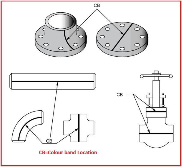
Piping Material color coding is developed to differentiate between various grades or specifications of materials. Color markings are assigned on the basis of nominal chemical compositions. The location of pipe marking shall be as follows:
- The pipe shall be marked with, for example, paint, dye, or tape for its full-length
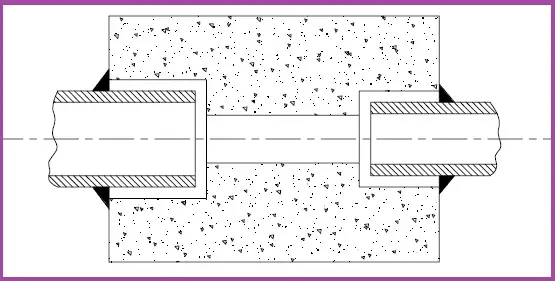
- Flanges shall be banded (Refer to Fig. 1) on the back of the flange at the intersection of the back face and the hub
- Pipe Fittings shall be stripped from bevel to bevel
- Miscellaneous material shall be color-marked so as to provide proper identity
- The paint shall not cover welded surfaces, heat marks, or any other identification
Pipe Service Markers
Permanent color pipe service markers shall be used for all process and utility piping systems within the plant.
Piping systems for pipe color coding shall include utility pipes of any kind and, in addition, fittings, valves, and pipe coverings. Piping systems shall be painted a neutral background color, for example, aluminum or grey, which shall not detract from the high visibility of the colors and lettering of the service markers.
Permanent color markers for piping systems shall be placed at the battery limit and at vertical risers at utility stations. Service markers shall be applied close to valves or flanges, and adjacent to changes in direction, branches, and where pipes pass over or through walls, floors, fences, or roads, and on straight pipe runs, sufficient for identification.
A service marker in English shall be used as the primary and explicit means of identification for the contents of all aboveground piping. Positive identification of the contents of a piping system shall be by a lettered legend giving the name of the contents in full or abbreviated form. Arrows shall be used to indicate the direction of flow. Additional details, for example, temperature or pressure, shall be added as necessary to highlight the degree of hazard.
Shutdown, emergency, or car-sealed valves shall be labeled with P&ID and valve numbers and any descriptive labeling needed to permit easy identification. Firewater system sectionalizing block valves shall be identified by their firewater system identification number.
Contrast shall be provided between the color field and legend for readability. For identification of materials in pipes of less than 3/4 inch (19 mm) in diameter, and for valve and fitting identification, the use of a permanently legible tag is recommended. The size of the service marker letters shall neither be less than 13 mm nor greater than 89 mm, varying in size depending on the outside diameter of the pipe.
For piping 2-inch NPS and smaller running between equipment, where the total length is less than 15 m, no pipe marking shall be necessary. For piping on pipe racks, pipe service marking shall be oriented in a way that it is visible from grade level and from any nearby platform.
The color of the service marker letters shall be black or white, whichever provides a greater contrast to the background color.
Pipe markings shall be clearly visible. Where pipelines are located above or below the normal line of vision, the lettering shall be placed below or above the horizontal centreline of the pipe.
Pipe Marking materials for stainless steel and nickel alloy piping shall not contain any harmful substances, for example, chlorides, fluorides, sulfur, and low melting point metals.
Pipe Color Coding and Marking Execution Process
Surface Preparation: Surfaces to be color-coded or marked shall be free from oil, grease, dirt, and other surface contaminants that might be detrimental to the adhesion of the paint used for color coding and marking.
Application of Pipe Color Coding and Pipe Marking
- Whenever color coding or marking paint is to be applied to a primed surface, the primer shall be dried completely before the color coding or marking paint is applied.
- Color coding, marking, and identification paint shall be applied to dry, clean surfaces in accordance with the manufacturer’s instructions.
- Unless otherwise recommended by the manufacturer, color coding and marking shall not be undertaken when the ambient temperature is less than 10 °C (50 °F), or the relative humidity is more than 90 percent.
- Color coding and marking paint shall be applied in 1 coat.
Industrial Pipe Color Coding Standards
There are several pipe color coding standards used around the world. Here are some of the most common ones:
- ANSI/ASME A13.1: This is a standard used in the United States to identify the contents of pipes in industrial settings. It recommends the use of specific colors and labeling requirements to indicate the type of fluid or gas being transported in the pipe.
- BS 1710: This is a British standard that provides guidance on the use of colors to identify the contents of pipes in buildings and industrial facilities. It recommends the use of specific colors and labeling requirements to indicate the type of fluid or gas being transported in the pipe.
- ISO 14726: This is an international standard that provides guidance on the use of colors to identify the contents of pipes in marine and offshore environments. It recommends the use of specific colors and labeling requirements to indicate the type of fluid or gas being transported in the pipe.
- DIN 2403: This is a German standard that provides guidance on the use of colors to identify the contents of pipes in industrial settings. It recommends the use of specific colors and labeling requirements to indicate the type of fluid or gas being transported in the pipe.
- AS 1345: This is an Australian standard that provides guidance on the use of colors to identify the contents of pipes in buildings and industrial facilities. It recommends the use of specific colors and labeling requirements to indicate the type of fluid or gas being transported in the pipe.
- PFI ES-22 – Recommended Practice for Color Coding of Piping Materials
- IS 2379 – Pipelines Identification Color Code
These standards provide guidance on the use of colors to identify the contents of pipes and ensure consistency and safety across different industries and regions.
Different codes mentioned above use different philosophies with respect to pipe color coding and pipe marking systems. For example, As per ASME A13.1, the following pipe color code system is followed:
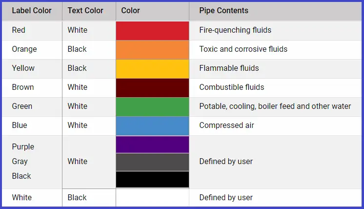
The pipe color coding system uses different colors to represent different types of fluids or gases, as well as to indicate the direction and function of the pipe. Here are some examples of the colors used in the pipe color coding system:
- Red: Used to indicate fire protection piping, as well as piping carrying flammable gases and liquids.
- Yellow: Used to indicate fuel gas piping.
- Green: Used to indicate piping carrying compressed air and other non-toxic gases.
- Blue: Used to indicate piping carrying potable water.
- Orange: Used to indicate piping carrying toxic or corrosive fluids.
- Brown: Used to indicate sewage and other waste materials.
- Black: Used to indicate piping carrying process gases and liquids.
- White: Used to indicate piping carrying steam.
Pipe Color Coding Chart
A pipe color coding chart is a reference tool that lists the recommended colors and labeling requirements for different types of pipes in a piping system. The chart helps workers quickly and easily identify the contents and function of pipes in industrial settings, which is important for safety and efficiency.
The pipe color coding chart typically includes the following information:
- Color coding: The chart lists the colors used to identify different types of pipes, such as red for fire protection, yellow for fuel gas, green for compressed air, and so on.
- Labeling requirements: The chart provides guidance on the labeling requirements for each type of pipe, including the information that should be included on the label, such as the contents of the pipe, the direction of flow, and any hazards associated with the pipe.
- Pipe types: The chart may also include information on the different types of pipes used in a piping system, such as metal, plastic, or composite pipes, and how they should be identified.
Pipe color coding charts are often based on industry standards, such as ANSI/ASME A13.1 in the United States or BS 1710 in the United Kingdom. By using a pipe color coding chart, workers can quickly and easily identify the contents and function of pipes in a piping system, which can help to prevent accidents and ensure that the system operates safely and efficiently.
Typical Examples of Pipe Color Codes
Industrial pipe color coding conventions may vary by region, industry, local codes, standards, and safety regulations. Here are some of the typical examples of pipe color codes.
Ammonia Piping Color Code:
- Pipe Color: Light Blue
- Label or Tape Color: White
- Purpose: Light blue is commonly used to indicate ammonia piping. White labels or tapes may be used for additional information or identification.
Utility Piping Color Code:
- Pipe Color: Green
- Label or Tape Color: Yellow
- Purpose: Green is typically used to identify utility piping, which can carry various non-hazardous fluids like air, compressed air, or cooling water. Yellow labels or tapes may be used to convey additional information.
Water Piping Color Code:
- Pipe Color: Blue
- Label or Tape Color: White
- Purpose: Blue is a universal color for water piping. White labels or tapes can be used to provide further details, such as the type of water (e.g., cold water, hot water) or other relevant information.
Oil and Gas Piping Color Code:
- Oil Pipe Color: Orange
- Gas Pipe Color: Yellow
- Label or Tape Color: Black
- Purpose: Orange is often used for oil pipelines, while yellow is the standard color for gas pipelines. Black labels or tapes may be used for identification and additional information.
Gas Pipe Color Code:
- Pipe Color: Yellow
- Label or Tape Color: Black
- Purpose: Yellow is the established color for gas piping, and black labels or tapes can be used to provide specific details or warnings.
Sewer Pipe Color Code:
- Pipe Color: Green (for non-potable sewage)
- Label or Tape Color: White
- Purpose: Green is used to signify sewer pipes carrying non-potable sewage. White labels or tapes can be used for additional information.
Plastic Pipe Color Code:
- Pipe Color: Various Colors (depending on the material and purpose)
- Label or Tape Color: Often matches the pipe color or follows standard conventions
- Purpose: Plastic pipes come in various colors based on the material and intended use. Labels or tapes usually match the pipe color or adhere to industry standards.
Steam Pipe Color Code:
- Pipe Color: Silver or Aluminum
- Label or Tape Color: Black
- Purpose: Silver or aluminum pipes are often used for steam, and black labels or tapes can be added for clarity and identification.
Power plant pipe color coding vs. Process/Chemical plant pipe color coding
There are differences between power plant pipe color coding and process plant pipe color coding, although there may be some overlap between the two systems.
In general, power plant pipe color coding tends to be more focused on identifying pipes carrying specific types of fluids or gases that are used in the power generation process. For example, power plant pipe color coding may use specific colors to indicate pipes carrying steam, condensate, feedwater, and cooling water.
Process plant pipe color coding, on the other hand, may be more focused on identifying the contents of pipes based on their chemical composition and physical properties. For example, process plant pipe color coding may use specific colors to indicate pipes carrying acids, bases, solvents, and other chemicals.
The specific colors used in power plant and process plant pipe color coding may also differ depending on the region and industry. For example, the colors used in power plant pipe color coding in the United States may be different from those used in Europe or Asia.
It’s important for workers in power plants and process plants to be familiar with the pipe color coding system used in their specific industry and region, as this can help prevent accidents and ensure the safe and efficient operation of the plant.