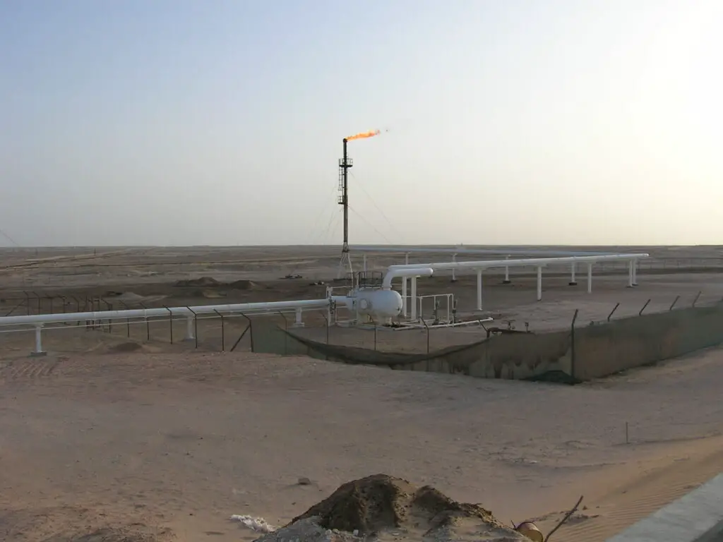
A Flare system is a means of safe disposal of waste gases by burning them under controlled conditions. Flare piping generally comprises of PSVs outlet piping, subheader piping & main header piping.
Design conditions considered for stress analysis are as per P&IDs, line list, and specific information related to flare if any by the process. A typical flare system consists of:
A knockout drum to remove and store condensable and entrained liquids.
Single or multiple burner units and a flare stack.
Fig. 1: Typical Flare pipe with Knock out Drum
The important points that a stress engineer should consider carefully are listed below:
Fluid Density of Flare Lines
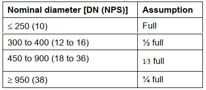
The Fluid density has to be taken from the Line list (Process Department). However, the density given in line designation tables (LDT) is normally very less. But different specification says to use an assumed liquid content while stress analysis of flaresystem lines. For example, Shell DEP 80.45.10.10 says to assume the following liquid content for stress analysis and support design load considerations.
Table: Liquid Content Assumption for Flare Lines
Pressure Test Method for Flare Lines
Flare lines are normally pneumatic tested. So, hydro test weight is not required to be considered during stress analysis. However, in specific cases, water-filled weight may be considered (Check with the Process department).
Supporting Flare Lines
Flare lines are normally provided with pipe slopes as per Process requirements/ Project specifications. So general practice is to support with Shoe/saddle supports. The pipe supporting span is to be maintained so that the sustained sagging should not exceed 5 mm (preferably below 3 mm). The structure below the pipe support/shoe height is to be planned to meet the piping sloping/free draining requirement.
Normal industry practice is to take 45 degrees/90-degree branch connections from Flare Header: Proper SIF (both in-plane and out-plane) should be incorporated at branch connections while entering data into the analyzing software. SIF s can be calculated using Fe-SIF, Nozzle Pro, or some other type of FEA software. Sometimes reinforcement may be required to reduce the SIF value. In absence of proper SIF values of 45 Degree Branch connections through FEA software, many organizations suggest a SIF value for a 45° branch connection as 2.25 times the SIF value of a 90° branch.
In a flare system sometimes a temperature gradient or profile may exist when the hot contents flow into the subheader / main header which is at a lower temperature ( confirmation with the process if required ).
Also, note that the minimum design temperature for flare headers is normally in the range of -50 Deg C. So there will be a wide difference between the maximum and minimum design temperature. So decide on expansion loop locations early in the project stage.
PSV/PRV Reaction Force
There are many PSV/PRVs that are connected to the flare header. It is always a better practice to consider all the PSV systems in a single system along with the flare header to get proper boundary conditions for all PSV/PRV systems. The reaction force for those PSV/PRVs needs to be collected/calculated beforehand. It is preferable to add Rest+Guide+Line Stop in the PSV outlet line and Hold down +Guide in the PSV inlet line. The reaction force is to be added considering one PSV/PRV is popping up and the other is not popping.
Piping Flexibility
Piping shall be evaluated for sufficient flexibility. If necessary expansion loops shall be provided. Expansion joints are to be avoided. Flare piping loops are planned in a horizontal plane (2D loops) in order to ensure pipe slope/free draining requirements. However, the number of loops should be minimized as much as possible.
Flare line routing and supporting are to be planned in such a way that forces and moments on flare knock-out drum nozzle connections are minimized.
Sometimes Flare line may consist of a two-phase flow. So Vibration/Acoustic analysis (AIV) is required to be performed and supporting to be strengthened.
Flare Stack and Knock Out Drum Nozzle Loads
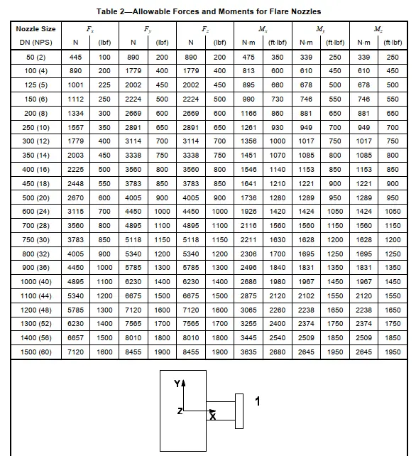
Knock-out drums are normal horizontal vessels and normally have high allowable nozzle load values. So there is no difficulty in qualifying these nozzles. But, Stack has low magnitude nozzle allowable loads. So pipe routing has to be sufficiently flexible to reduce the nozzle loads. Consult with the flare stack vendor at the initial stage and collect the allowable load values early to avoid major design changes at a later stage.
API 537 standard, Table 2 provides some typical values for Flare stack allowable nozzle loads and moments based on nozzle sizes. A part of the flare stack allowable nozzle loads from API 537 standard is reproduced here.
Fig. 2: API 537 flare stack allowable nozzle loads
Site selection for a plant is an important activity for any project. Careful considerations of various factors keeping in view the corporate objectives are required for any company. Such considerations will finally make the plant economically and technologically viable and it will contribute to the environment. Strategic, long-term, and non-repetitive sound decisions are required. During the final decision-making, a certain degree of imaginative future planning will help to a great extent.
What are the factors for Site Selection?
Most of the time, the industrial development policies of the Government of the country where the plant will be situated dictate the allocation of the site. In addition to that, there are various other factors that need to be considered. A few such important factors are briefed in the following paragraphs.
Location Factor for Site Selection
The location factor is of utmost importance and requires careful consideration because of its long-term consequences. Any mistake during the selection of an appropriate location can be costly. Improper location comes with the following major problems:
A higher cost means higher investment.
Difficult marketing and transportation.
Dissatisfied and frustrated employees and consumers
Low availability of high-caliber professionals.
Frequent interruptions of production and
Abnormal wastage.
Also, once a plant is set up at a particular location, it is almost impossible to shift to a better location later because it will again involve numerous economic, political, and sociological reasons. Employee welfare, employment opportunities, etc are a few of the social reasons whereas, the pursuit of a policy of regional development and planning can be a political reason.
At the same time, The location factor needs the consideration of the following facilities.
District Classification
This will ensure that the license for locating the plant in a no-industry district is obtained.
Transportation Facilities
Proper transportation facilities linking with ports and railroads are crucial for the uninterrupted transfer of raw materials and end products. Airport-Connection is important for the easy movement of professionals. In case, foreign collaborations are involved in the plant, these points will be more crucial.
Availability of Manpower
Local access to skilled and semi-skilled manpower will add to the efficient construction and operation of the plant.
Industrial Infrastructure
Sufficient Industrial infrastructure will aid all supporting services required for the successful operation, maintenance, and repair of various machines and other items, availability of workshops, plant services, etc. that may not be feasible to be generated within the factory premises. The availability of communication facilities plays an important part in the infrastructure. Existing vibrant infrastructure in the vicinity is much preferred than the need-based infrastructure getting developed after the plant commissioning.
Community Infrastructure
As all the plants of modern times operate on sophisticated technology, it would be necessary to attract qualified professionals. This means, ensuring a good quality of living is a must. The availability of good schools and colleges, medical services, good communication facilities, cultural and recreational opportunities, etc will be required. Attracting qualified professionals will be very difficult in the absence of good community infrastructure.
Availability of Raw Water
The plant should be located in close proximity to an adequate quantity of water sources. Water will be required for plant operation and other non-plant activities. As the groundwater may be depleted at a future date, drawing the water by boring deep tube wells without the provision of a perennial source is not recommended. The Natural Water Table and flooding history need to be duly considered.
Effluent Disposal
The drainage facility for the Effluent disposal must be examined. It would be economic if an effluent disposal facility after treatment is readily available. Otherwise, there may be legal and ecological consequences in transporting the effluent by drainage to a safe disposal area that far away.
Availability of Power
The required amount of uninterrupted and stable power (without fluctuations in voltage and frequency) for the successful operation of the plant is very crucial. The plant cost can be reduced by locating the plant near to power source.
Wind and Seismic Factors
Careful consideration of Prevailing wind direction, Maximum Wind Speed, and seismic history for the preferred site must be checked.
Availability of Industrial Gas
Nowadays, Industrial gas is the preferred source of energy for many plants as it is highly efficient and contributes very little towards industrial pollution. An uninterrupted power supply and a gas-based captive steam power generation unit are of great importance. Hence, the nearness of the site to a gas distribution network will be advantageous for long-term planning and future expansions.
Size and Nature of the Site for Selection
The plot area, the topography, the township facilities, and future expansions should meet the plant requirements. It is preferred if the grade level of the entire area is the same. In case, the plot area is not flat, it must be leveled to suit the plant’s requirements. The degree of required leveling and filling should be looked into from economic considerations.
Load-bearing capacity and acidity of the soil play a major role in the selection of the site. Filled soil has got less load-bearing capacity as compared to Natural Soil. As a consequence, the civil foundation will be economic in natural soil because piling to support heavy loads will not be needed whereas in a case-filled soil normally piling is required.
Ecology and Pollution
Nowadays, there is a great deal of awareness of the maintenance of natural ecological balance. Regarding the effect of pollution from specific types of plants, social obligations are to be met. The nature of the site selected should preferably have some advantages to meet these requirements.
Quantitative Analysis
The above factors are considered at the time of site selection and the data collected are analyzed, generally by the weight-rating method, in order to finalize the recommendation of the potential site.
In the weight rating method, variable weights are assigned to each factor. Then each site is evaluated on a 0-5 sliding scale for each of these factors. The assignment of points for each site for each factor is obtained by multiplying the rating of the site by the weight of each factor.
The overall site rating is then obtained as the sum of the assigned points for each site. The recommendation will be for the site to have a maximum overall rating.
System Earthing or Grounding can be defined as a conducting connection whether intentional or accidental by which an electrical circuit or equipment is connected to the earth.
Types of Grounding
System Grounding
Equipment Grounding
System Grounding
The System grounding is the intentional connection of neutral conductor to earth.
Purpose of System Grounding
Controlling the voltage to earth within predictable limits
Provides flow of current that will allow detection of an unwanted connection between system conductors and Ground and which may instigate operation of automatic devices to remove the source of voltage from conductors with such undesired connection to ground
Methods of Grounding
Ungrounded Systems (No intentional Grounding)
Provides continuity of supply in case of 1-ph to ground faults
No expenditure required for Grounding system
Excessive overvoltages during arcing, resonance ground faults
Grounded Systems
Greater Safety
Freedom from excessive over-voltages
Easier detection and location of ground faults
Resistance Grounded
Limits earth fault current and subsequent effects on the connected equipment
Reduces momentary line-voltage dip
Control of transient overvoltage
Reactance Grounded
Ground fault current should be preferably 60% of 3-ph fault current to prevent serious transient overvoltage. This is considerably higher fault current than resistance grounded system
Grounding Fault Neutralizer
Reactance is tuned to System charging current so that the resulting ground-fault current is resistive and of low magnitude
Current and voltage are in phase, So if a ground fault is in the air (insulator failure) it is self-extinguishing
Solidly Grounded Systems: Direct connection for systems with Ro<=X1 and Xo<=3X1
Equipment Grounding
The Equipment grounding refers to interconnection and grounding of all non-electrical metallic elements of a system
Purpose of Equipment Grounding
To reduce electric shock hazard to personnel
To provide adequate current-carrying capability both in magnitude and duration to accept ground-fault current permitted by the overcurrent protection system
To provide a low impedance return path for ground-fault current necessary for the timely operation of the overcurrent protection system
Safe Grounding Design
Objectives for safe grounding design
To provide means to carry electric current into the earth under normal and fault conditions without exceeding any operating and equipment limits or adversely affecting continuity in service
To assure that a person in the vicinity of grounded facilities is not exposed to the danger of critical electric shock
Safe grounding strives at controlling the interaction of the two grounding systems as follows:
The intentional ground consisting of ground electrodes buried at some depth below the earth surface
The accidental ground temporarily established by a person exposed to a potential gradient in the vicinity of the grounded facility
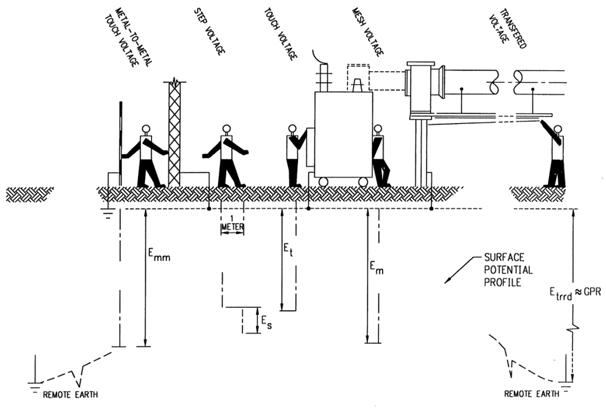
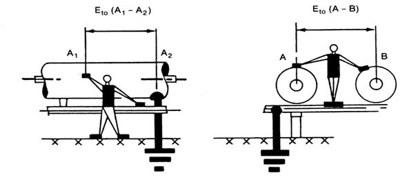
Basic shock situations (Fig. 1):
Fig. 1: Figure showing the basic shock situation
Ground potential rise: The maximum electric potential that substation grounding grid may attain relative to a distant grounding point assumed to be at a potential of remote earth
Mesh Voltage: The maximum touch voltage within the mesh of the ground grid
Metal to metal touch voltage: The difference in potential between metallic objects within substation site that may be bridged by direct hand to hand or hand to feet contact
Step Voltage: The difference in surface potential experienced by a person bridging a distance of 1m with the feet without contacting any other grounded object.
Touch Voltage: The potential difference between ground potential rise (GPR) and the surface potential at the point where a person is standing while at the same time having a hand in contact with the grounded structure
Transferred Voltage: A special case of touch voltage where a voltage is transferred into or out of substation from or to a remote point external to the substation site.
Metal to metal touch situation (Fig. 2):
Fig. 2: Figure showing metal to metal touch situation
Grounding Design
Designed based on IEEE 80-2000
Critical parameters for Design:
Maximum grid current
Fault Duration and Shock duration
Soil resistivity
The resistivity of the Surface layer
Grid Geometry
General Concept of Grounding Design
Combination of Vertical rods and horizontal conductors
Horizontal conductors (grid) installed in a shallow depth (0.3 – 0.5m) are most effective in reducing the danger of high step and touch voltages on earth’s surface
If the magnitude of current dissipated to earth is high it is seldom possible to install a grid with resistance so low so as to assure that rise of ground potential will not generate surface gradients unsafe for human contact. The hazard can be eliminated only by control of local potentials through the entire area by using ground rods.
Soil Treatment for Grounding
It is often impossible to achieve the desired reduction in ground resistance by adding more grid conductors or ground rods
An alternate solution is to increase the diameter of the electrode by modifying the soil surrounding the electrode by use of the following materials
Use of Sodium chloride, magnesium and copper sulfate, etc.
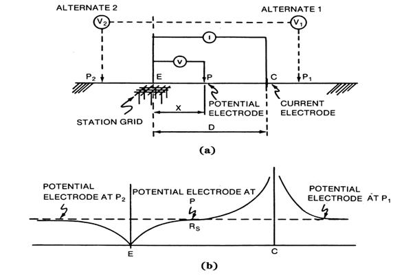
Field Measurements –Fall of the potential method (Fig. 3):
Ground resistance measurement consists of measuring the resistance of the grounding system with respect to the remote ground electrode
It has difficulties and errors when used for large grounding systems
Fig. 3: Field measurements
Survey of Potential contours and Touch and Step voltages:
Use the existing power lines and remote substation as current electrode
Pass test current through substation ground grid via remote current electrode as in substation ground resistance measurements
Measure Touch and Step voltages.
The test values are multiplied with a ratio of actual fault current to test current to obtain potential under fault conditions.
Disturbance due to noise and electrical interference influences the results.
A new approach of measurement: OMICRON CPC-100 can be used to generate current at a Lower and higher frequency than power frequency. Using digital filter algorithms the test set will measure only the signal with a frequency that is currently generated and filters out signals at other frequencies. Disturbance due to noise and electrical interference thus no longer influence the result.
Tank Protection against overpressure due to a fire near the tank or other abnormal upset conditions
Comply with Legal Requirements
Implementation of Advisory Organization Recommendations
Meet Environmental Regulations
Minimize Loss of Stored Products
Follow Corporate Safety Standards
Why would a customer need an Emergency Vent?
Provides emergency pressure relief in case of a storage tank fire or other abnormal pressure conditions
As storage tank contents rise in temperature, the emergency vent allows for the required venting capacity, preventing tank rupture
Prevents tank from rupturing due to overpressure
Operates when relief capacity exceeds normal vent capacity
Available in pressure/vacuum and pressure-only configurations
Larger sizes permit access to the tank
Wide variety of materials available
Codes and Standards for Tank Venting
As per OSHA 29CFR1910.106 Tanks Storing: Class IA Liquids shall be equipped with a venting device; Class IB & IC Liquids shall be equipped with a venting device or with an approved flame arrester; Every above-ground storage tank shall have some form of construction or device that will relieve excessive internal pressure caused by fire
Atmospheric & Low-Pressure Tanks – the normal operating pressure shall not exceed the design pressure.
Low-Pressure Tanks can be used as an Atmospheric Tank
Atmospheric Tanks – API 650
Low-Pressure Tanks – API 620
Normal vent sizing shall be in accordance with API 2000 or other accepted standard
Vents 2” thru 12” size must be flow tested
Vents > 12” in size – flow may be calculated using a flow coefficient of 0.5
API 2000 – Venting Atmospheric and Low-Pressure Storage Tanks
The circumstances that must be considered for calculating the overpressure or vacuum in a tank are:
Liquid Movement into and out of the tank
Tank breathing due to weather changes
Fire Exposure-Emergency vent
Other circumstances resulting from equipment failures and operating errors
Calculating Venting Requirements
OSHA 1910.106 states “Normal Venting” shall be sized in accordance with API 2000, Venting Atmospheric and Low-Pressure Storage Tanks
Emergency Venting requirements are given in OSHA 1910.106 but are exactly the same as API 2000
API 2000 states that we need to consider, as a minimum:
Liquid Movement Into or Out of a Tank
Weather Changes
Fire Exposure
Operating Errors and Equipment Failures
Other forms of Emergency Venting
Emergency Venting requirements may take the form of a floating roof, lifter roof, weak roof-to-shell seam, or other approved pressure-relieving construction.
For a tank roof to be frangible one of the requirements is the tank diameter must be 50 ft. or greater.
Venting of Atmospheric Storage Tanks:
Tanks Designed to operate at pressures from atmospheric through 0.5 psig
Tanks shall be built in accordance with acceptable good standards of design API 650
Protected against excess internal pressure or vacuum from exceeding the tank design pressure or vacuum
Shall have some form of construction or device that will relieve excessive internal pressure caused by fire exposure at or below the design pressure.
Venting of API 620 Low-Pressure Storage Tanks:
Designed to operate at internal pressures above 0.5 psig but not more than 15 psig
Should be built in accordance with acceptable standards of design API 620
Shall have some form of construction or device that will relieve excessive internal pressure caused by exposure fires. Shall be vented to prevent the internal pressure from exceeding the design pressure of the tank plus 20%.
Types of Emergency Vents
Direct-Acting Vents
weight-load vents
spring-loaded vents
Pilot Operated Vents
Characteristics of Weight-Loaded Vents
The setpoint is determined by the total pallet weight
Flow at SetPoint is Zero
Overpressure is needed to Open Vents
Vents have a maximum possible setting
Flow curves or charts are used to represent the flow characteristics of a particular size, configuration, and setpoint of a vent
Characteristics of A Pilot Operated Vent Valve (POVV)
Setpoint is determined by adjusting the pilot set screw
Flow at SetPoint is Zero
The valve is almost bubble-tight up to the set pressure
The valve is fully open at 10% Overpressure
Vents have a maximum possible setting of 14.0 PSIG
Flow curves or charts are used to represent the flow characteristics of a particular size, configuration, and setpoint of a vent
Vent Setting
The Minimum Setting is Pallet with no Loading Weights
The maximum setting is limited by the number of weights without restricting lift on the Top Guided 3400 & 3800 Model.
Weights are usually made of Lead, Carbon Steel, Stainless Steel, FRP Encapsulated
Weights can add considerable weight to vent
The Set Point of a Weight-Loaded Vent
SetPoint = Total Pallet Assembly Weight/Seat Area
For Example: If the total weight of the pallet assembly = 10.945 lbs; The set area of the vent = 21.89 in2; Then the set point would = 10.945 lbs / 21.89 in2 = 0.5 PSIG = 8.0 Oz/In2 = 13.84” WC
Procedure for Selection of Vent (Using Flow Curves)
Decide on which model of vent will be used and obtain the flow curves for all sizes of that model available
Top Guided or Bottom Guided
Calculate the vent flow (SCFH) required in the application, considering tank size.
If you do not have a specific set point and only have the Tank Design Pressure and the required flow. Start with the smallest size, and look at the flow at the tank design pressure. If it is less than the required flow calculated or given, go to the next size larger. Continue to do this until you reach a size that will meet or exceed the flow requirement. This is the size vent to use.
After picking the proper size, choose a setpoint such that the entire required relieving capacity is met exactly at the allowable overpressure
Various Vent Configurations
PRESSURE ONLY VENT TO ATM: Bottom Guided Manhole Cover, Hinged Style, 16” thru 24”
PRESSURE ONLY VENT TO ATM: Top Guided, 2” Thru 24”
PRESSURE ONLY VENT WITH PIPE-AWAY: Top Guided for Venting to a safe distance, 2” Thru 12”
COMBINATION PRESSURE & VACUUM VENT WITH PIPE-AWAY: Top Guided for Venting to a safe distance, 2” Thru 12”
COMBINATION PRESSURE & VACUUM VENT TO ATM: 2” Thru 12”
Emergency Vent: Manhole Cover
Applications: Petroleum, Petrochemical, Chemical, Pharmaceutical, Food and Beverage, Water and wastewater, Pulp & paper
Benefits: Relieves emergency flow due to excessive venting requirement from a fire burning around a storage tank; High Flow Capabilities; Easy installation and convenient handling for inspection; Tank examination requires no gasket replacement or unbolting; Low base for overflow
Sizes: 16”, 20”, 24” diameter manholes for tank inspection
Emergency Vent: Top Guided & Self-Reseating Type
Applications: Petroleum, Petrochemical, Chemical, Pharmaceutical, Food and Beverage, Water and wastewater, Pulp & paper
Benefits: Relieves emergency flow due to excessive venting requirement from a fire burning around a storage tank; High Flow Capabilities; Easy installation and convenient handling for inspection; Tank examination requires removal of weather hood and pallet
Benefits: Relieves emergency flow due to excessive venting requirement from a fire burning around a storage tank; Easy installation and handling for inspection; No gasket replacement or unbolting is necessary, eliminating the expensive manpower needed to put conventional emergency vents back in operation; Pallet construction permits a wide variety of pressure settings; A flexible diaphragm affords a tight seal between the pallet and the corrosion-resistant seat below set pressure. This also assures low leakage. The diaphragm is intended for normal ambient temperature storage.
Sizes: 16”, 20”, 24”
Hinged Cover
Spring Loaded Emergency Vent
Applications: Petroleum, Petrochemical, Chemical, Pharmaceutical, Food and Beverage, Water and wastewater, pulp & paper, Natural gas industry
Benefits: Spring Loaded Emergency Relief for Higher Design Pressures; Simple, yet Rugged Design; Superior Flow Characteristics; 1 to 15 PSI Settings
Sizes 16”, 20” and 24”
Emergency Vent and Manhole Cover (Pressure and Vacuum)
Applications: Petroleum, Petrochemical, Chemical, Pharmaceutical, Food and Beverage, Water and wastewater, pulp & paper.
Benefits: Versatile design incorporates pressure and vacuum relief; Reduced maintenance costs; No need to unbolt vent for gasket replacement or tank examination; Unique “self-energizing” diaphragm construction assures tight seal between pallets and seats; 20” diameter manhole for tank inspection; Low base for overflow
Information Required for calculating the emergency Venting Requirement
Type of Tank: Horizontal, Vertical, Sphere, Etc.
API 650, 620, or other
Tank Dimensions
Design Pressure
Relieving Temperature
Operating Pressure & Relief Vent Setting
Product to be Stored
MW & latent Heat of Vaporization if sizing for the actual product
Determine the total wetted surface area of the tank (π x D x Ht.)
See API 2000, Table 3A for the required Emergency Venting for Fire Exposure vs. Wetted Surface Area based on Hexane
For Vertical Tanks: The wetted surface area is equal to the total surface area of the vertical shell to a height of 30 feet above grade. If the vertical tank is sitting on the ground, the area of the ground plate is not included. If it’s supported above grade, then the bottom plate is to be included as an additional wetted surface area.
For Horizontal Tanks: The wetted surface area is equal to 75% of the total surface area or the surface area to a height of 30 feet above grade, whichever is greater.
For Sphere and Spheroids: The wetted surface area is equal to 55% of the total surface area or the surface area to a height of 30 feet above grade, whichever is greater
API Allows taking Credit for other Vents on the same Storage Tanks by subtracting the maximum available flow of the Conservation Vent from the Emergency Vents Required Flow
API method used to calculate the emergency venting requirement is based on a product that has the characteristics of Hexane
Most of the time this is adequate but there are some cases where this method will underestimate the emergency venting requirements.
What is Pipe Stress Analysis? A Comprehensive Guide
Piping Stress Analysis is the most important activity in Piping Design. Once, pipes are routed following design guidelines, they need to be verified by piping stress analysis to ensure they will work smoothly throughout their design life. This article will explain the basic points for Piping Stress Analysis. Piping Stress Analysis is also termed Piping Flexibility Analysis.
What is Pipe Stress Analysis?
Pipe Stress Analysis is an engineering activity that focuses on evaluating the stresses, deformations, and forces within a piping system. It plays a vital role in ensuring the safe and reliable operation of piping systems in various industries, including oil and gas, petrochemical, power generation, and more.
Limiting sagging & displacement within allowable values.
3. Optimal Design:
Avoiding excessive flexibility and high loads on supporting structures. Aim towards an optimal design for both piping and structure.
Basic Concepts of Piping Stress Analysis
Piping Components
Pipe stress analysis considers various components like pipes, fittings, valves, and supports. Understanding the properties and behavior of these components is crucial for accurate analysis.
Pipes: Different materials, sizes, and schedules are used for pipes, and they exhibit specific stress-strain behaviors.
Fittings and Valves: These components introduce stress concentrations and affect the overall behavior of the system.
Supports: Supports and restraints are essential for controlling pipe movements and distributing loads.
Load Types
Pipe systems experience several load types, including:
Static Loads: Steady-state conditions like internal pressure, deadweight, and thermal expansion.
Dynamic Loads: Transient events such as water hammer, relief valve discharge, and seismic activity.
Thermal Loads: Temperature variations causing thermal expansion and contraction.
Stress-Strain Relationships
Pipe stress analysis relies on understanding the stress-strain relationship of materials. Key concepts include:
Elasticity: Materials return to their original shape when the load is removed within their elastic limit.
Plasticity: Beyond the elastic limit, materials deform irreversibly.
Creep: Slow, time-dependent deformation under constant load and elevated temperature.
Governing Codes and Standards for Pipe Stress Analysis
Sustained Stresses are the stresses generated by sustained loads. (e.g. Pressure, Weight). These loads are present continuously throughout plant life.
Resistive force arising out of sustained stresses balances the external forces keeping the system in equilibrium. Exceeding sustained allowable stress value causes catastrophic failure of the system. As per ASME B 31.3, (clause 302.3.5):
“ The sum of the longitudinal stresses, SL, in any component in a piping system, due to sustained loads such as pressure and weight, shall not exceed “Sh“. Where Sh=Basic allowable stress at the metal temperature for the operating condition being considered.
Change in length of a pipe of length L due to temp change (ΔT) is given by ΔL=L α ΔT Here, α =Co efficient of thermal expansion = change in length of unit length element due to unit change in temp.
Two “α” values (denoted by A and B) in Code (Table C-1 and C-1M in ASME B31.3 Appendix C):
The thermal Co-efficient “A” of Table C-1 denotes the mean coefficient of linear thermal expansion between 70 degrees F to the indicated temp (μin/in/0F).
The thermal Co-efficient “B” of table C-1 denotes total linear thermal expansion between 70 degrees F to Indicated temp (unit=in/100ft).
Table C-1M provides thermal co-efficient values in the metric system.
Expansion stresses are generated when the free thermal growth due to temperature change is restricted. These are self-limiting or self-relenting.
Stress Intensification Factor in Piping Stress Analysis
SIF( Stress Intensification Factor): This is the ratio of the maximum stress intensity to the nominal Stress. SIF factors for different components can be obtained from Appendix D of ASME B31.3 till edition 2018. From ASME B31.3-2020 onwards Appendix D has been deleted. Now users are required to use ASME B31J or FEA for finding the values of SIF.
Equations for Calculating Expansion Stress Range and Allowable Stress Value
The displacement Stress Range due to thermal expansion is calculated based on equation SE per equation 17 from ASME B31.3( clause 319.4.4).
This SE value shall not exceed the SA value where SA= Allowable Displacement Stress Range.
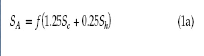
As per ASME code B 31.3 (Clause 302.3.5) the allowable displacement stress range (SA) can be given by the equation (Fig.2):
Fig.2: Equation for Displacement Stress Range Allowable
Here, f= Stress range reduction factor and Sc= basic allowable stress at minimum metal temp
When Sh > SL, the allowable stress range is calculated by the following equation (Fig. 3): SL=Longitudinal Stress due to sustained loads.
Fig.3: Equation for Liberal Displacement Stress Range Allowable
Occasional Piping Stresses
Occasional Stresses are generated by occasional loads such as Wind, seismic, PSV discharge, etc.
These loads act in a piping system for a very short period of time, usually less than 10% of the total working period.
As per ASME B31.3, clause 302.3.6 “The sum of the longitudinal stresses, SL, due to sustained loads, such as pressure and weight, and of the stresses produced by occasional loads, such as wind or earthquake should be ≤ 1.33 times the basic allowable stress, Sh”
The code does not explicitly explain the stresses generated due to vibration.
The vibration problems are solved by engineering judgment and experience.
Reducing Piping Stresses
Piping stresses can be reduced by various methods like
Providing Support at a suitable span to reduce Weight (Sustained) stresses.
Providing Flexibility to reduce piping expansion stresses generated by thermal loading e.g. Expansion Loops, Offsets, and Inclusion of elbows to change direction.
Flexibility Analysis Requirement (as per clause 319.4.1, ASME B 31.3):
Clause 319.4.1 of ASME B31.3 states that
No formal stress analysis of adequate flexibility is required for a piping system that (a) duplicates, or replaces without significant change, a system operating with a successful service record. (b) can readily be judged adequate by comparison with previously analyzed systems. (c) is of uniform size, has no more than two points of fixation, no intermediate restraints, and falls within the limitations of the empirical formula given below in Fig. 4
Fig.4: Flexibility Check Equation for Simple Systems
This means all other piping connections that do not fall in the above-mentioned group need to be analyzed. As most of the lines will not fall in any of the above groups, the numbers of lines requiring stress analysis will be huge. That is why organizations based on their experience group the lines as mentioned below and decide the method of stress analysis requirement:
Stress Criticality and Analysis Methods
Highly Critical Lines (Steam turbine, Compressor connected lines, jacketed piping system, very high-temperature pipes, Non-metallic pipes, etc): Stress analysis is to be performed by Computer Analysis
Moderately Critical Lines (AFC connected lines, Pump connected lines, pressure vessel connected lines, etc): Stress analysis to be done by Computer Analysis
Low critical Lines: Visual/Simple Manual Calculation/Computer analysis and
Pipe materials have defined stress limits to ensure their safety. The basic allowable stress for a pipe material is calculated as follows:
Minimum of (As per ASME B 31.3)
1/3rd of the Ultimate Tensile Strength (UTS) of Material at operating temperature.
1/3rd of UTS of material at room temperature.
2/3rd of Yield Tensile Strength (YTS) of material at operating temperature.
2/3rd of YTS of material at room temp.
100% of average stress for a creep rate of 0.01% per 1000 hr.
For structural grade materials basic allowable stress=0.92 times the lowest value obtained from 1 through 5 above.
Loads on a Piping System
There are two types of loads that act on a piping system: Static loads and Dynamic Loads
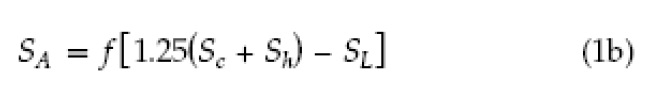
Fig.5: Examples of Static Loads
Static loads are those loads that act very slowly and the system gets enough time to react against it. Examples of static loads are shown in Fig.5
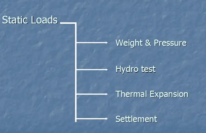
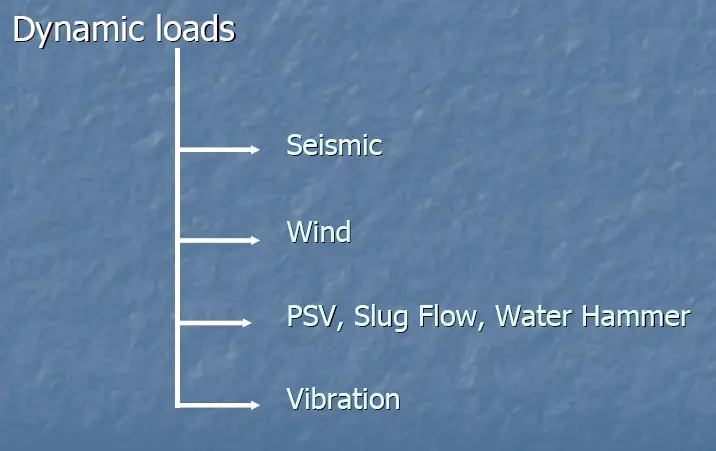
Fig. 6: Examples of Dynamic Loads
On the other hand, dynamic loads act so quickly that the system does not get enough time to react against them. Examples of dynamic loads are shown in Fig.6
Work Flow Diagram for Pipe Stress Analysis
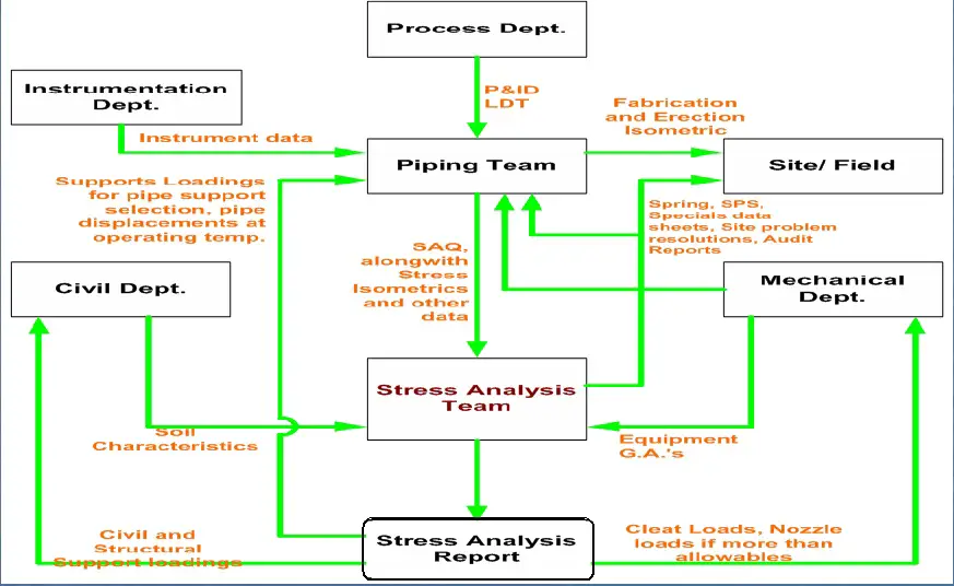
The interaction of the Piping Stress team with other disciplines in any organization is shown in Fig. 7:
Fig.7: Inter-Departmental Interaction with Stress Team
Pipe Stress Analysis Software Programs
Here’s a list of some widely used pipe stress analysis software programs
CAESAR II developed by Hexagon PPM (formerly Intergraph)
ROHR2 by Sigma Ingenieurgesellschaft mbH
PASS/START-PROF by PASS Engineering
AutoPIPE by Bentley Systems
ANSYS Pipe (part of ANSYS Mechanical) by ANSYS, Inc.
Caepipe developed by SSTUSA
Among all the above, Caesar II is the most widely used piping stress analysis software package and comprehensively used worldwide. Further details about pipe stress analysis software programs are mentioned here.
Modeling the piping system in Caesar using parameters from stress Iso.
Analyzing the system and obtaining results.
Conclusion & Recommendation:
Whether to accept the system or to suggest necessary changes in layout and support to make the system acceptable as per standard requirements.
Outputs from Stress Analysis | Stress Analysis Deliverables
The major pipe stress analysis deliverables are listed below
1. Final marked-up Isometric drawings (Stress isometrics) to Layout: The stress markup isometric consists of all the recommendations marked on the stress isometric drawing. In general, the following information is provided in stress isometric:
Node numbers of all relevant points.
Support Types (Rest, Guide, Line Stop, Spring Hanger, Anchor, or mix of Rest, Guide, or Line Stop Support)
Displacements at the interface points and wherever more than the normal acceptable limit.
Pipe routing changes if required.
Additional support if required.
Preliminary spring hanger details like Tag number, hot load, cold load, hydro test load, vertical maximum displacement, etc.
Shoe lengths in case the length has to be increased from the standard length.
Preliminary support arrangement drawing in case non-standard support is used.
Equipment Nozzle Node Numbers.
Trunnion Length and Reinforcement requirements, etc
Page Continuation number
Any special notes
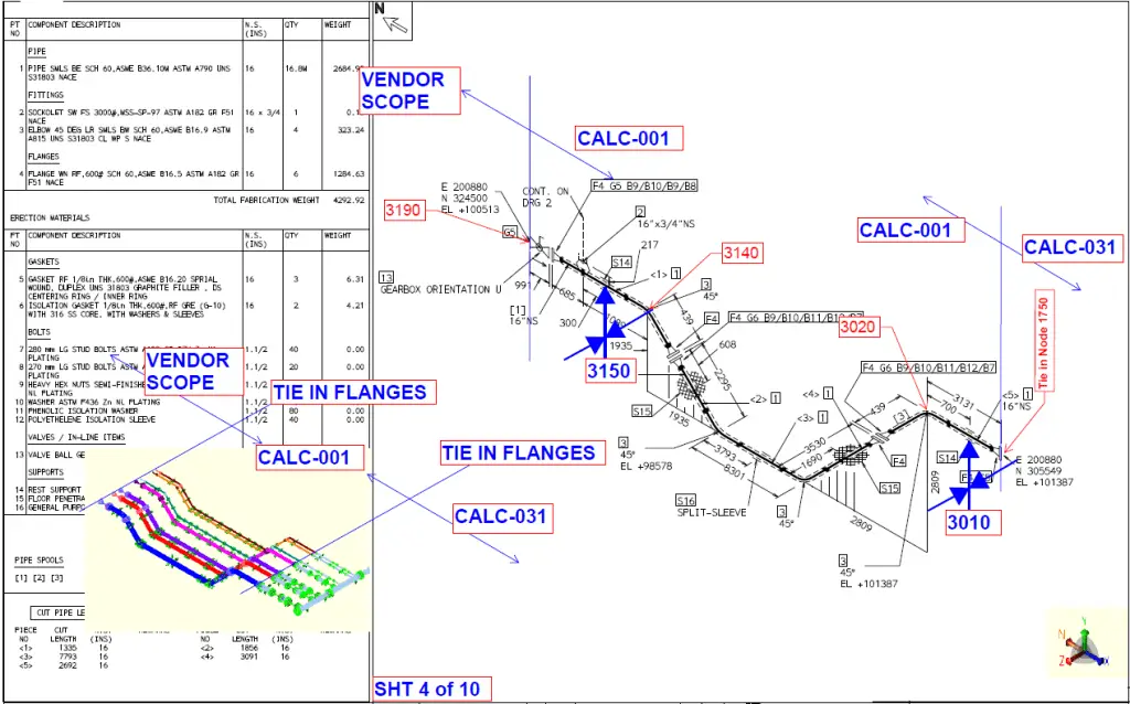
Axis markup with respect to the north direction of isometric drawing. Refer to Fig. 8 for a typical stress mark-up isometric.
2. Support Loads to Civil for support member design: Support loads are transferred to the civil team along with the isometric markup drawing to understand the node number and support location. Usually, loads are transferred in an Excel sheet format. The different company applies different formats for providing loads to civil and structural departments. In general, the following information is provided:
Vertical Load, Axial Load, and Lateral load in consistent units.
A general cushion/margin is used based on project-specific criteria while providing loads.
Notes to be considered
In general, the loads from the following load cases are provided separately:
Hydrotest loads
Design temperature loads (Both maximum and minimum design temperature cases)
Maximum of all the operating and sustained load cases (excluding occasional loads)
All individual pure occasional loads
Empty pipe loads
Mention in notes that the civil team should consider the vertical load and act in a downward direction. The axial and lateral loads are to be considered to act in both positive and negative direction and the worst case will govern.
For Hold down supports specifically provide the vertical uplift force that will act on the support.
8. Clip or Cleat location and loading information to pressure vessel/tank vendors for their design and fabrication work.
Fig. 8: Typical Stress Mark-up Isometric Drawing
Loads and Load Combinations for Piping Stress Analysis
Pressure Loads
Internal and external pressure loads must be accurately analyzed to determine their impact on the piping system.
Temperature Changes
Temperature fluctuations can cause significant thermal stresses, particularly in large, high-temperature systems.
Deadweight and Operating Loads
The weight of pipes, fittings, valves, and insulation contributes to the system’s overall load.
Wind and Seismic Loads
External forces like wind and seismic events must be considered in high-risk areas.
Water Hammer Effects
Water hammer, or hydraulic shock, occurs when there is a sudden change in fluid flow, resulting in pressure surges that can damage piping systems.
Pipe Stress Mitigation Techniques
Redesign
Modifying the piping layout or design to reduce stress concentrations and improve overall system performance.
Adding Supports or Expansion Joints
Introducing additional supports or expansion joints to reduce stress and accommodate thermal expansion.
Reinforcement
Strengthening critical areas of the piping system to withstand higher loads and pressures.
Pipe Stress Analysis Books
To learn the basics of pipe stress analysis, every pipe stress engineer should refer the following books on piping stress analysis
Pipe Stress Engineering by Peng
DESIGN OF PIPING SYSTEMS by M W Kellogg Company
Piping Handbook by Mohinder L. Nayyar
Introduction to Pipe Stress Analysis by Sam Kannappan
Piping Stress Handbook by Victor Helguero
COADE STRESS ANALYSIS SEMINAR NOTES by Hexagon
PIPING DESIGN HANDBOOK by John Mcketta
THE FUNDAMENTALS OF PIPING DESIGN by Peter Smith
Type of Pipe Supports
Pipe Stress Analysis will be incomplete without a few words about piping supports. Piping stress analysis, in one way, is the selection of proper supports and placing them in the correct location to avoid detrimental stresses in the piping systems. Various types of supports are used in the piping and pipeline industry like
Rest Support: Restrict downward movements.
Guide Support: Arrest lateral movements.
Line Stop or Axial Stop: Restrict axial or longitudinal movement of the pipe.
Anchor Support: Completely fixed. Restrict all six degrees of freedom. The pipe at this support point can’t translate or rotate.
Variable Spring Hanger Support: Flexible support, acting as Resting support with flexibility to thermal movements.
Constant Spring Hanger: Flexible support, that acts as Rest support allowing thermal displacements.
In piping stress analysis supports can be classified into two groups
Uni-Directional Piping Support and
Bi-Directional Pipe Support.
Unidirectional pipe support is free to move in one direction like +Y, +X, +Z, etc here the supports are free to move in +y, +x, and +z respectively. However, bi-directional piping supports arrests movement in both directions like Y, X, or Z supports.
Basics of Piping Stress Analysis Tutorial Video
To learn the above-mentioned points in detail refer to the following video:
Basic Piping Stress Analysis Video Tutorial
Pipe Stress Analysis Online Video Course
If you wish to explore more about pipe stress analysis, then the following online pre-recorded video course is highly recommended: Caesar II Pipe Stress Analysis
Questionnaire for Piping Stress Analysis
What are the various types of loads that cause stresses in the piping system?
Which code do we refer to for Refinery Piping?
Which standard governs the design of Pumps?
The coefficient of thermal expansion of a substance is 1.8 mm/m/Deg.F. What is its value in mm/mm/Deg.C.?
Calculate the minimum pipe thickness of a seamless 10” NB A106- Gr B material with a design pressure of 20 bars. (Design Temp= 350 degrees C and Corrosion allowance= 1.6 mm)?
Modeling Fired Heater Piping Connection is a bit tricky as the pipe is not welded to a fired heater shell similar to ordinary equipment. The heater has a hole, the pipe runs through that hole inside the heater body.
There are two techniques for modeling fired heater piping connection:
First method: Use an anchor at the point where the piping goes inside the heater. The heater vendor must provide the allowable loads for this anchor point. Or the API 560 code may be used
Second Method: Model the whole or part of the furnace coil that is inside the heater. The vendor should provide allowable displacements at the point where the pipe goes inside the heater (+dx, -dx, +dy, -dy, +dz, -dz). Usually, it’s the gap values between the pipe and heater shell
You can choose one of these two methods.
First Method – Allowable Loads
The first method is very conservative. The loads on the fired heater usually are very huge, but allowable loads are very small and can’t be met.
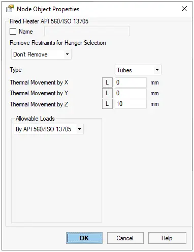
In START-PROF software the “Fired Heater” Object can be used.
Allowable Nozzle Loading Method of Fired Heater Piping Connection Model
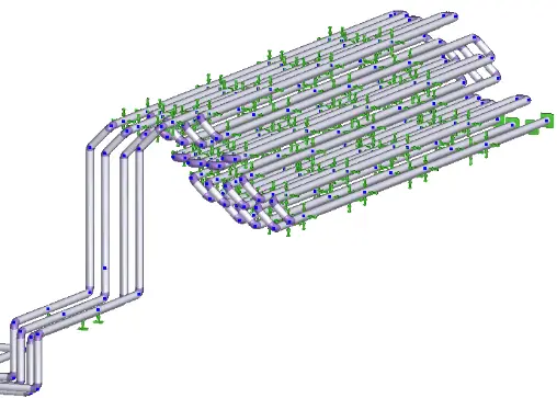
Second Method – Allowable Displacements
Using the second method it is easier to satisfy the vendor requirements. There’s no need to model the whole furnace coil, just 3-4 U-Tubes are enough.
Allowable displacement model of Fired Heater Piping Connection model
The supports in the furnace coil should be modeled correctly.
The following conditions should be met:
Pipe displacements at the point where pipe hoes inside the heater should be less than the vendor’s allowable
All stresses both in the pipe and in the furnace coil should be less than allowable according to the selected code
Loads on the furnace coil supports should be less than allowable