14 major changes in ASME B31.3-2016 with respect to its earlier edition (ASME B31.3-2014)
Most of you are aware that the latest edition of Process Piping Bible (ASME B31.3-2016) is issued on 31st January 2017 and This Code will become effective 6 months after the Date of Issuance (i.e. from August 2017 onwards).
There are many changes in this edition with respect to its earlier edition. This article provides only 14 major changes that readers will find in that code. Readers are requested to list down other major changes in the comments section.
1: For the first time the code provides some reference for a piping system that has already been placed in service. For existing piping systems, The code suggests using ASME PCC-2, Repair of Pressure Equipment and Piping, and API 570, Piping Inspection Code: In-service Inspection, Rating, Repair, and Alteration of Piping Systems.
2: A new section for rounding of values (Test data or dimensions) based on ASTM E29 is added in clause 300.1.4.
3: The conventional definition of severe cyclic conditions (either equivalent no of cycles>7000 or Se>0.8Sa) has been modified in this edition. As per B 31.3-2016, Designating piping as being under severe cyclic conditions should be considered when piping is subjected to both a high-stress range (when the calculated stress range approaches the allowable stress range) and many cycles (the stress range factor, f, is less than the maximum, fm).
4: New Appendix R (Use of Alternative Ultrasonic Acceptance Criteria) is added. The fracture mechanics ultrasonic acceptance criteria in Appendix R may be used for acceptance of discontinuities if all requirements of Appendix R are met.
5: In the 2014 edition, for the first time the code provided stress values in MPa in table A-1M and Table A-2M. Those metric values are partly provided and were equivalent to their FPS (KSI) counterparts. Please note that In the 2016 edition The values stated in ksi (Table A-1 and Table A-2) are not exact equivalents to the values stated in MPa (table A-1M and Table A-2M). Therefore, for any given material, the user of the Code should use only the ksi or the MPa values.
6: As per the latest edition of the code; In no case shall a coupling or half coupling have a rating less than Class 3000 in accordance with ASME B16.11.
7: In B31.3-2016 when inplane and out plane SIF’s (for sustained stress sustained moment index) are determined by experimental or analytical means the bending stress calculation for branch pipe is permitted using section modulus of parent pipe (not branch pipe). However, if SIF’s from Appendix D are used branch section modulus to be used.
8: As per the latest code the Impact testing is not required if the design minimum temperature is greater than or equal to −104°C (−155°F) and the stress ratio (as defined in Fig 323.2.2B of the code) does not exceed 0.3. and For stress ratios greater than 0.3, the lowest design minimum temperature permitted is −48°C (−55°F). Also, it has included Tabular Values for Reduction in Lowest Exemption Temperature for Steels Without Impact Testing.
9: The minimum PWHT holding temperature for P-No. 15E, Group No. 1 material may be 675°C (reduced by 45°C from 2014 edition) for nominal material thicknesses ≤13 mm (1⁄2 in.).
10: The Assembly requirements for bolted flanged joints are added in clause 335.2.5.
11: Now Hardness tests are not required to verify proper heat treatment except as otherwise specified in the engineering design.
12: When piping sub-assemblies are tested separately, A special provision for testing is provided in clause F345.2.3 where consideration should be given to performing an additional leak test of the assembled piping system with nonhazardous test fluid prior to initial operation and Examination for leaks should be at all joints that have not been previously examined for leaks, or that have been reassembled after being examined for leaks.
13: Piping systems designed for vacuum service may be subjected to a vacuum leak test (in place of leak testing under internal pressure)method by a qualified and certified Leak-testing personnel with technique and acceptance criteria specified by the owner following a written procedure complying with the applicable technical requirements of the BPV Code, Section V, Article 10.
14: During leak testing, the Joints previously tested in accordance with this Code may be insulated or covered. Also At the owner’s option, for Category D Fluid Service, joints that are subject to a hydrostatic leak test or an initial service leak test may be insulated and have protective weather sheathing installed prior to leak testing. However, Consideration shall be given to increasing the test period to allow time for possible leakage to pass through the insulation and weather sheathing.
Learn the ASME B31.3 code changes in different years:
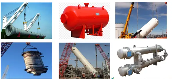
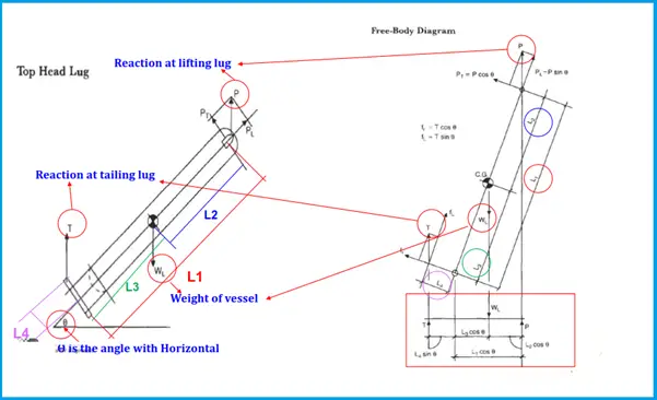
A Lifting lug is a plate with a hole in it. As the term specifies, lifting lugs are used for lifting. The hole is sized to fit a clevis pin. Using lifting lugs combined with the clevis pins, loads are transferred from one mechanical component to another. For mechanical static equipment (Fig. 1), these lifting lugs are used by cranes for transportation and installation.
While lifting this mechanical equipment, the lugs must be able to carry the complete weight of the equipment. Also, while transporting and installing various kinds of forces act on those lifting lugs. Hence, the lifting lug design has to be accurate enough to avoid any failure. In this article, we will briefly explore the lifting lug design methodology.
Types of Lifting Lugs
Lifting lugs are commonly used in process industries to facilitate the safe and efficient lifting and transportation of heavy equipment and components. Here are some common types of lifting lugs used in process industries:
Fixed lugs: Fixed lugs are permanently attached to the equipment or component and are designed to provide a secure lifting point. Fixed lugs are typically welded or bolted to the equipment and are load rated to ensure they can safely support the weight of the equipment.
Swivel lugs: Swivel lugs are designed to rotate around a central axis, which allows the lifting force to be evenly distributed and reduces the risk of the equipment or component twisting or turning during lifting. Swivel lugs can be fixed or removable and are often used in conjunction with spreader bars to lift large or irregularly shaped equipment.
Adjustable lugs: Adjustable lugs are designed to accommodate different sizes and shapes of equipment and can be adjusted to fit the specific lifting points of the equipment. Adjustable lugs are typically bolted or clamped onto the equipment and can be adjusted to ensure a secure lifting point.
Hinged lugs: Hinged lugs are designed to pivot around a central axis, which allows the lifting force to be evenly distributed and reduces the risk of the equipment or component twisting or turning during lifting. Hinged lugs can be fixed or removable and are often used in conjunction with spreader bars to lift large or irregularly shaped equipment.
Removable lugs: Removable lugs are designed to be attached and detached from the equipment or component as needed. Removable lugs can be bolted or clamped onto the equipment and are often used in situations where a permanent lifting point is not feasible or when the lifting points of the equipment need to be changed frequently.
Overall, the type of lifting lug used in a process industry will depend on the specific application, the size and shape of the equipment being lifted, and the required load capacity. It’s important to select the appropriate lifting lug and to ensure that it is properly installed and load-rated to ensure the safe and efficient lifting and transportation of equipment and components.
Lifting Lug Arrangements for lifting Vessels
Fig. 1 below shows the lifting lug arrangements that are attached to pressure vessels for industrial use.
Fig. 1: Lifting Arrangements for Vessels
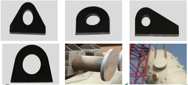
Lifting Lug Shapes
Lifting lugs can be of various shapes as shown in Fig. 2. The shapes are decided by manufacturers.
Fig. 2: Shapes of Lifting Lugs
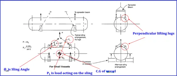
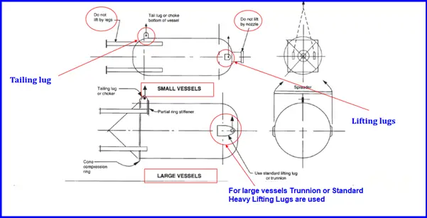
Lifting Lug Arrangements for Horizontal Vessels
Fig. 3 shows widely used industrial lifting arrangements during construction for horizontal vessels.
Fig. 3: Lifting Arrangements for Horizontal Vessels
Lifting Arrangements for Leg-Supported Vessels
Fig. 4 shows typical lifting arrangements popularly used for vertical vessels in industries.
Fig. 4: Lifting Arrangements for Vertical Vessels
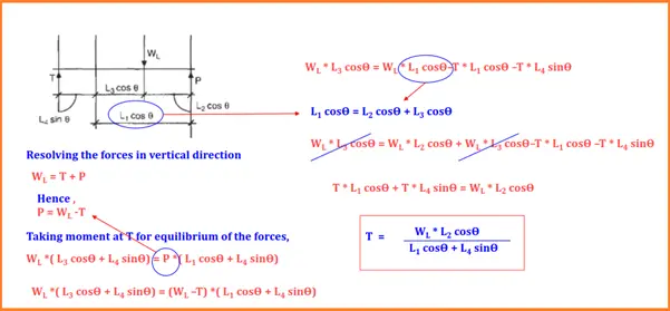
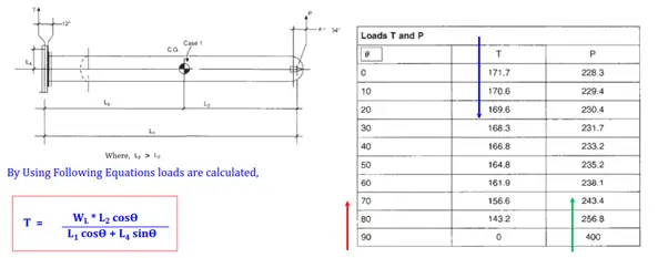
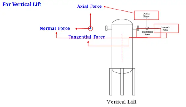
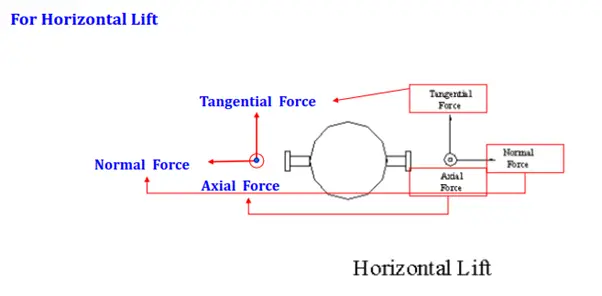
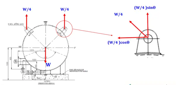
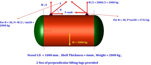
Forces in Lifting Lug Design
Horizontal to vertical lifting Forces:
Horizontal to vertical lifting Forces Calculations:
Horizontal to vertical lifting Forces Calculations with Sample Problem:
Lifting Lug design Standard
ASME BTH-1 “Design of Below-The-Hook Lifting Devices.” governs the design of lifting lugs for industries. For producing a safe reliable design, This is the most widely used lifting lug design standard. However, As such standards do not clearly address the local stress calculation steps, Finite Element Analysis is performed using various software like Ansys, PV-elite, etc.
Lifting Lug Design
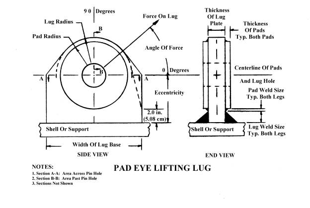
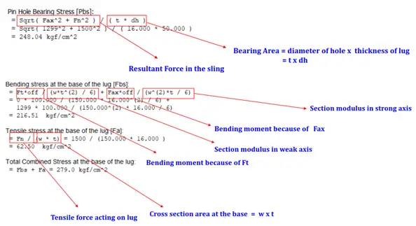
Lifting lug design is very critical and hence mostly done using FEA software. The basic design of a lifting lug consists of the following four parts;
the design of the lug plate,
verifying the weld used to connect it to a shell or structure,
checking the bearing stress at the pin-hole and
confirming the end area of the lug.
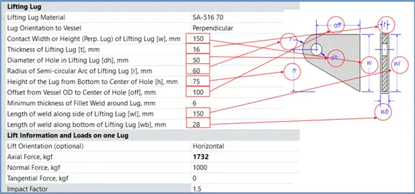
The following image shows the parts of a Pad-Efe Lifting Lug.
Part of a typical lifting lug
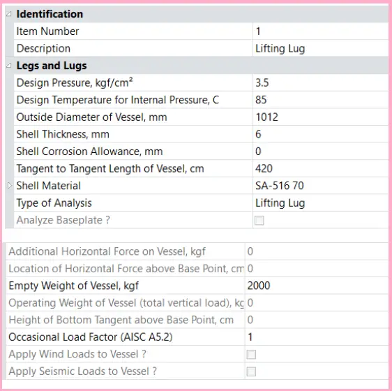
In the following section, we will see the design methodology followed for lifting lug design using PV-Elite software.
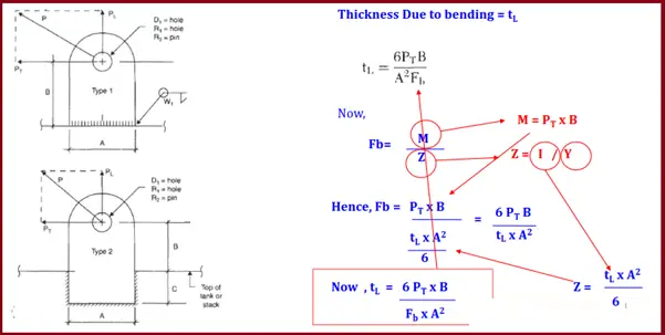
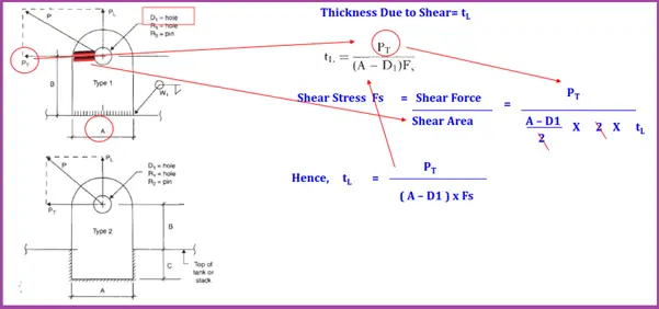
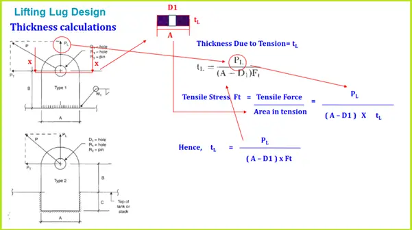
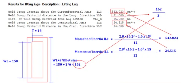
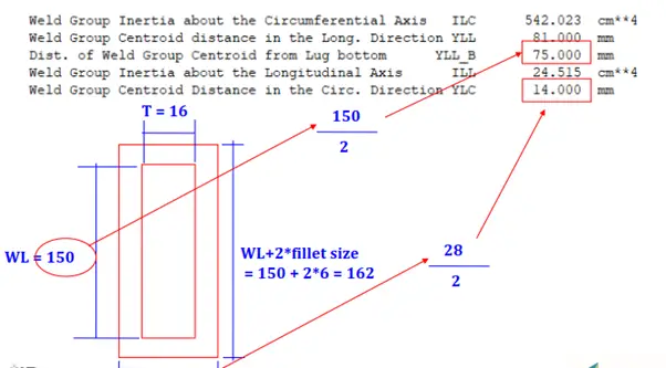
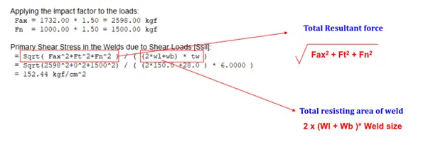
Lifting Lug design Thickness calculations:
PV Elite Forces and sign Conventions:
PV Elite Lifting Lug Sample Example
Factors Affecting Lifting Lug Design
Designing lifting lugs for process equipment and components requires careful consideration of a range of factors to ensure safe and efficient lifting operations. Some of the factors that can affect the design of lifting lugs include:
Load capacity: The lifting lugs must be designed to safely support the weight of the equipment or component being lifted, as well as any additional weight from rigging, slings, or lifting accessories.
Load distribution: The lifting lugs must be designed to evenly distribute the lifting load across the equipment or component to prevent damage or distortion during lifting.
Center of gravity: The lifting lugs must be positioned at the appropriate location to ensure that the equipment or component is lifted in a stable and balanced manner.
Equipment design: The lifting lugs must be designed to accommodate the specific shape and size of the equipment or component being lifted, as well as any protrusions or obstructions that may affect the lifting operation.
Rigging and lifting accessories: The lifting lugs must be designed to accommodate the type and size of rigging and lifting accessories being used, such as slings, shackles, and spreader bars.
Environmental factors: The lifting lugs must be designed to withstand the environmental conditions of the lifting operation, such as temperature, moisture, and corrosive substances.
Standards and regulations: The lifting lugs must be designed to meet applicable industry standards and regulations, such as ASME B30.20, which outlines the design requirements for below-the-hook lifting devices.
Overall, the design of lifting lugs for process equipment and components requires careful consideration of a range of factors to ensure safe and efficient lifting operations. It’s important to work with experienced engineers and rigging specialists to select the appropriate lifting lug and to ensure that it is properly designed, load rated, and installed.
This presentation is prepared by Mr. Deepak Sethia who is working in ImageGrafix Software FZCO, the Hexagon CAS Global Network Partner in the Middle East and Egypt. He has extensive experience in using Caesar II and PV Elite software and troubleshooting.
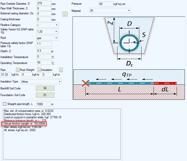
What if Piping Continuation is Unknown? Part 2. Underground Piping
What if Underground Piping Continuation is Unknown?
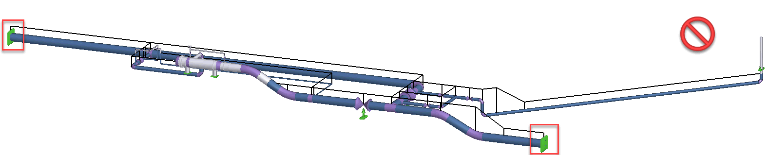
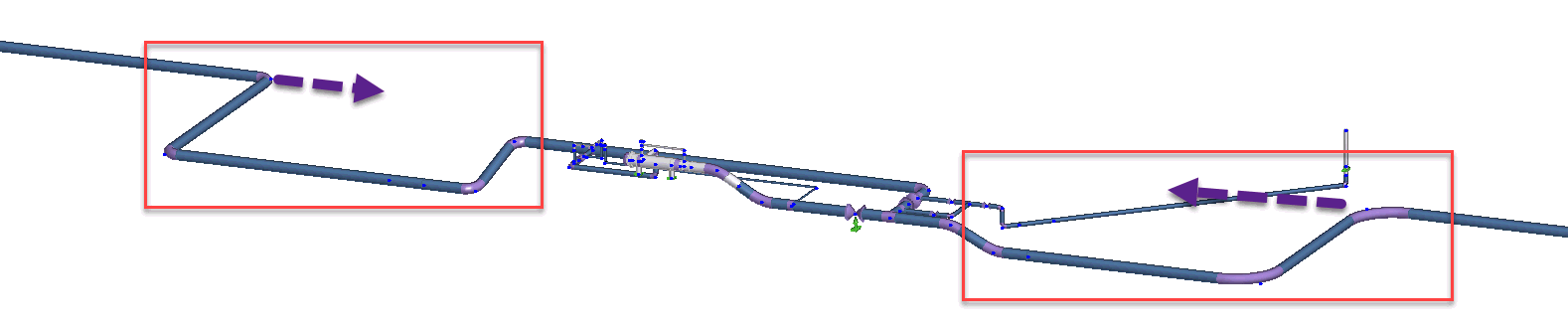
It is necessary to specify the correct boundary conditions while modeling main pipeline stations: valve station, pig launcher, pump and compressor station etc. Sometimes engineers use anchor or hinged anchor (rest+guide+limit stop in other software) at the points of connection to the main pipeline. This trick work for above ground piping, but doesn’t work for buried main pipelines. The wrong model of pig launcher station is shown below.
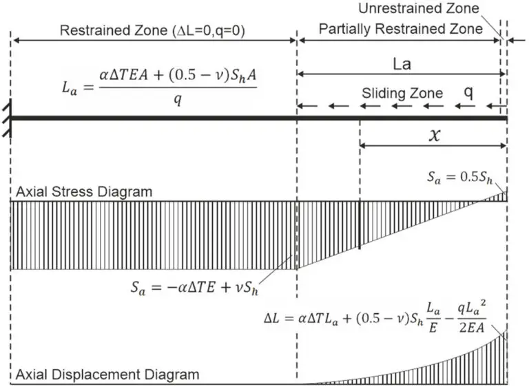
For a very long buried pipeline the anchor is not enough to achieve enough safety margin. Even if temperature difference between installation and operation temperature is very small 10-40 degrees, then temperature expansion can be up to 100 mm due to huge length. Such a big displacements can damage the piping inside the station.
To correctly model the temperature expansion model must include the part of main pipeline with a length greater than La. Where La is a sliding zone length, also called virtual anchor length. In sliding zone pipe moves along it’s axis. But in restrained zone pipe doesn’t move. The maximum displacement umax will be a constant for any length of pipeline greater than La. For more information about this, please refer this arcticle.
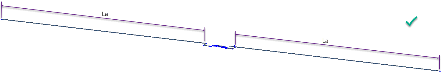
To correctly model the temperature expansion of main pipeline, just add the pipe with length greater than La value (see picture below).
La value can be found by three ways:
Using Manual Calculations
Using Start-Elements Procedure
Using step-by-step pipeline length increasing
Using Manual Calculations
The equation for “La” is given on the picture above
Using Start-Elements Procedure
Start-Elements is a special part of PASS/START-PROF software that allows to calculate wall thickness of pipes, bends, tees, reducers, spacing between the supports, stability analysis and much more.
To select the pipe length just add the pipe with some initial length. For example 100 m. Then run analysis and check stresses or support loads. Then increase the pipe length, for example to 150 m and run analysis again. If stresses or support loads become greater, then you need to increase the pipe length again and repeat analysis. Continue increasing of the pipe length until the stresses or support loads become almost the same as at previous analysis. It means that the pipe length already greater than La. START-PROF analysis is a very fast and allows to run analysis several times per short period of time, so this method is easiest.
Then the correct model is ready, maybe you will need to add U-, Z- or L-shape pipe loops to compensate the temperature expansion of connected main pipeline that is shown by dotted arrow on the picture below.
Please see the related video at 24:20, like, share and follow our channel:
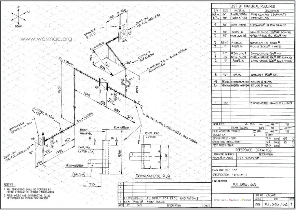
Piping Isometric Drawings | Symbols, How to Read, Software | Piping Isometrics
Once the three-dimensional (3D) model has been established in piping design software like PDS, PDMS, or SP3D, Piping Designers/Engineers need to convey that information to the yard for fabrication and the site for Construction. The transferred information must be sufficient for the fabricator with the vision of what is to be fabricated and how the piping should be connected with other elements, with exact dimensions and a complete build/Bill of materials (BOM). This is where Piping Isometric Drawings play a magnificent role. So piping isometrics are directly used for the following situations:
For Construction Services
For marking up deviation during site modifications/ as-builting.
For reference as Stress Analysis model built-up and the final stress markup for updating stress requirements.
Uses of Piping Isometrics
Isometric Drawings for Piping help to calculate many parameters required during project execution like:
Inch Meter can be estimated as the Length of pipe (in meters) x Size of pipe ( in inches).
Inch Dia is calculated as the Size of the Pipe joint ( in inch) x No, of Joints.
Pipe Weight is calculated as π x diameter of the pipe (in m) x length (in m) x thickness (in mm) x density of pipe material. The density of CS = 7.85 g/cm3.
The volume of Water required for hydro testing is estimated as π x {Pipe ID (in meter)}² x Length of Pipe.
Insulation Area (in m²) can be found as [π(Pipe OD+ insulation thickness)] (all in meter) x Length of Pipe (in meter).
Additionally, isometric piping drawings serve the following purposes:
Maintenance teams use isometric drawings to understand the existing piping layout and plan for repairs or modifications.
Fabricators and construction teams use these drawings to cut, assemble, and install piping systems accurately.
Engineers and designers use isometric drawings to plan and design piping systems, ensuring all components fit together correctly and meet design specifications.
What is Piping Isometric Drawing?
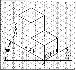
By definition, Isometric drawings are a pictorial representation that combines height-width-depth/length into a single view with 30 degrees from its horizontal plane as shown in the attached image.
Built-up of Isometric Drawing
It is a detailed 3D representation of a piping system that allows for visualization and understanding of the system’s layout, components, and flow paths.
Features of Piping Isometric Drawing
An isometricDrawing is a two-dimensional (2D) drawing that represents the 3D piping system. Sometimes piping isometrics are also known as pipe fitting isometric drawings. The important features are
It is not drawn to the scale, but it is proportionate with the exact dimensions represented.
Pipes are drawn with a single line irrespective of the line sizes, as well as the other configurations such as reducers, flanges, and valves.
Pipes are shown in the same size. The actual sizes are notified in the Bill of Material, tagging, call-out, or notes.
A piping isometric drawing provides all the required information like:
Piping and Component descriptions with size, quantity, and material codes
Precise dimensions for all components and the distances between them are provided.
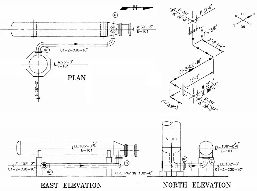
Piping Isometric drawings are popular because of their simplicity, yet efficient in conveying complex information. The following figure gives an example of how one Isometric drawing can represent three orthographic drawings. That is just a simple piping drawing. Imagine complex design and yet orthographic drawings are used for construction, that is really a headache.
Orthographic Vs Isometric Drawing
In earlier days, Isometric drawings were hand-drawn. With the innovation and advancement of the digital age, isometrics are drawn by AutoCAD/Microstation software. In recent days, 3D models could automatically extract the Isometric with a single click of a mouse.
Example of Piping Isometric Drawing
Creating a piping isometric drawing template can help standardize the process and make it easier to produce consistent and accurate drawings. However, the isometric drawing template may differ from one organization to another.
How to Read Piping Isometric Drawings?
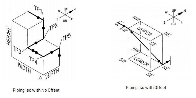
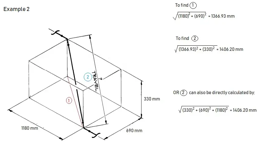
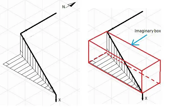
1. Imagine that the piping system is built in a box. This basic imagination is required for the piping to have an offset. So, it will help you to imagine, how the piping configuration will look as it travels.
Generation of Piping Isometric
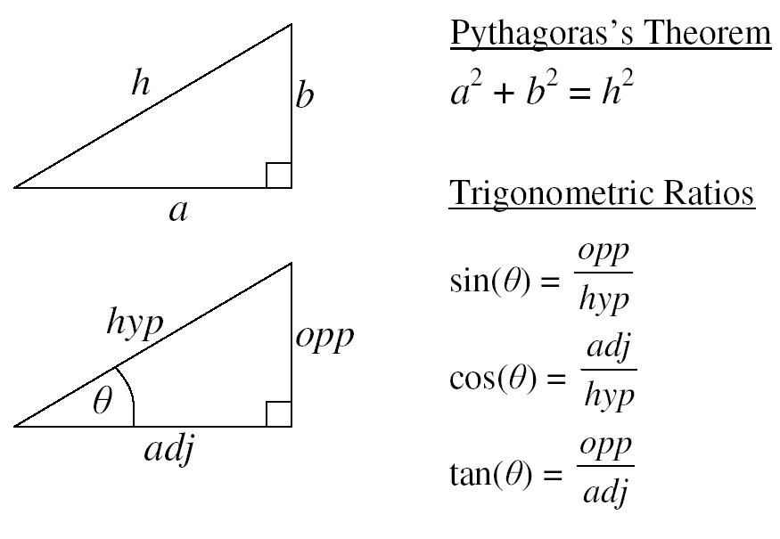
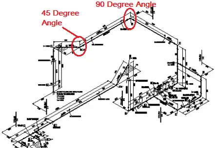
2. Offset happens when the pipe turns to any angle other than 90 degrees or to accommodate the odd nozzle’s location or tie-in point connections. A popular use is a 45-degree elbow and this is used extensively in piping design. In such cases, piping design may land on Northeast, Southeast, Northwest, or Southwest axes. In order to check the dimension of pipe length with offset, common Pythagoras’s theorem and Trigonometric rule can be used. A sample calculation is shown below as a reference-
Pythagoras Theorem
Length Calculation in Piping Isometric Drawing Examples
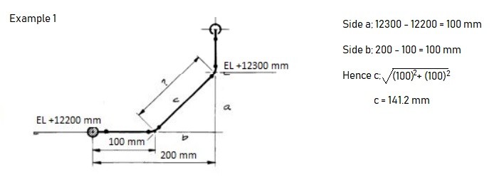
Example 1 of Pipe Length Calculation
Example 2 of Pipe Length Calculation
Example of offsets in Piping Isometric Drawing
Image showing Offset in Pipe Isometric Drawing
If you happen to have difficulties reading the offset, try to draw the imaginary box. It could help you have a better understanding of which axes the pipe travels and how the piping should look like. In the example given, take the flow from ‘x’, the pipe goes up; then up-northwest; then north. As you get along with Iso a lot, things will come naturally.
Piping Isometric Drawing Rolling:
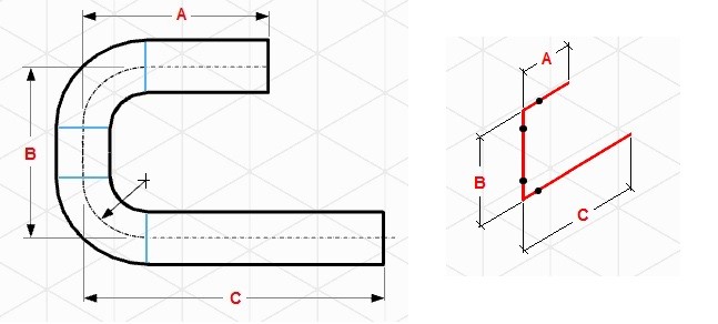
In piping isometric drawings, “rolling” refers to the change in direction of a pipe in more than one plane. A “roll” occurs when a pipe changes direction both horizontally and vertically simultaneously. This is a common occurrence in complex piping systems where space constraints or other design considerations necessitate such a change. Sometimes, the 3D offset is also known as rolling in the piping isometric drawing.
3. A North arrow is provided in all piping isometrics to inform the location of the piping system in the piping/ general arrangement drawing.
4. The piping isometrics also has coordinates & elevation detailed information to verify the exact length of the pipe in horizontal and vertical axes respectively. The dimensions in Isometric drawings are measured from the pipe centreline and not from the outer diameter of the pipe (refer to the image attached below for reference).
Piping Dimension in Isometrics
With the advancement of technology, there could be minimum or even zero possibilities that the North arrow, coordinates, and elevation in Isometric would differ from the piping arrangement; hence the dimensions and MTO should match exactly if the source 3D model is the same.
However, It is always better to check and verify as there could be some issues with the modeling itself that may cause discrepancies in material and quantity. For example, if double piping is modeled by mistake, it will read the double quantity of material.
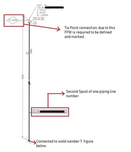
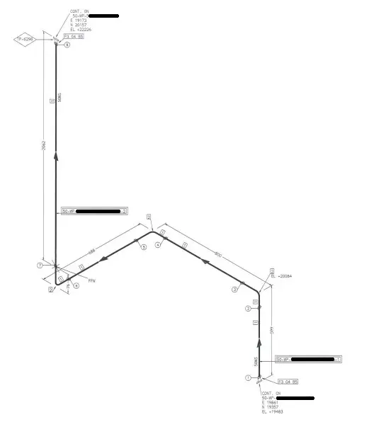
5. Isometric pipe drawings also inform which piping should be constructed at the fabrication shop and which should be assembled at the construction/platform field itself. The complete piping system is separated into pieces that are transported to the site for erection. These small pipe pieces are termed piping spools. One sheet of Isometric drawing normally has few spools.
Every weld that is assembled between spools at the construction site is termed a field weld (FW). There is one more type of weld that is known as field-fit weld (FFW). This FFW is defined by the designer if he/she could foresee that the spool might require some adjustment before the final fit-up, so at the location of FFW that has been marked, it will be given some pipe length tolerance (commonly 150-300mm). Usually, FFW will occur at the nozzle of equipment or tie-in locations.
FFW at Tie-in Point
FFW example 2
The whole assembled piping will look like the following after it is assembled at the field.
Assembled Drawing
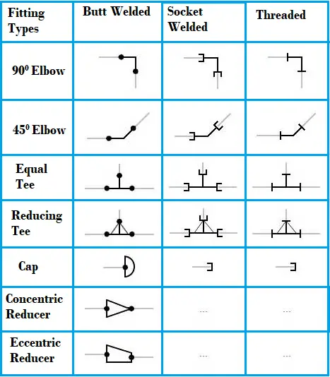
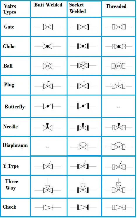
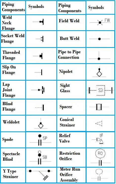
Piping Isometric Drawing Symbols
For reading and understanding a piping isometric drawing, one should learn the piping isometric drawing symbols thoroughly. Usually, all these piping and pipeline drawing symbols are similar and do not vary much from one organization to another. Knowing the isometric drawing symbols for piping and pipeline will provide various information like:
Type of Piping Joint: Piping and pipeline drawing symbols throw lights on the type of joint like Buttweld, socket weld, or Threaded.
Type of Piping Components: Piping symbols for Isometric drawings serve as a ready reference for the type of fittings and components.
Instrument items: Knowing the piping isometric symbols will help in recognizing the instrument and special piping items in the isometric.
Equipment Connection: Equipment connected to a piping system is also understood with piping symbols.
Knowing piping symbols for isometric drawing is useful in preparing MTO/BOM.
Examples of commonly used piping isometric drawing symbols are shown below for reference purposes
Piping Isometric Symbols for Pipe Fittings
Piping Isometric Symbols for Various Valve Types
Piping Isometric Symbols for Various Piping Components
Piping Isometric Drawing 45 Degree Angle Example
A typical example of piping isometric drawing that includes a 45 degree direction change is shown below:
Piping Isometric Example with 45 Degree Angle
Piping Isometric Drawing Software
Piping isometric drawing software is an essential tool for piping engineers and designers to create detailed isometric drawings of piping systems. These tools generate the 3D representation of the piping layout, including pipe dimensions, fittings, valves, and other components. There are many piping isometric drawing software programs available in the market which makes the task of a piping designer very easy. The piping isometric drawing software packages are two types; 2D software and 3D software. In 2D software, the piping isometric is generated manually whereas 3D piping isometric software programs have the capability of automatic isometric generation.
Top Piping Isometric Drawing Software Tools
Choosing the right piping isometric drawing software tool may be difficult as there are various options available. However, most design consultancies choose the complete software program considering the complexity of the job, costs, and client requirements. Here are some popular piping isometric drawing software tools:
AutoCAD
AutoCAD is the most widely used 2-D tool for Piping Isometric Drawings. To edit or modify any part of the isometric, piping designers frequently make use of this software.
AutoDesk Plant 3D:
AutoDesk Plant 3D is an industry-standard software for piping design and isometric drawing. It offers specialized tools for creating and editing piping layouts, generating isometric drawings, and managing pipe specifications.
CADWorx:
CADWorx, developed by Hexagon PPM, is a 3D plant design and modeling software that integrates with AutoCAD to provide piping engineers with tools for generating isometric drawings, equipment modeling, and structural design.
AVEVA E3D (Everything3D):
AVEVA E3D is a next-generation 3D design and modeling software that supports detailed piping design and the creation of isometric drawings. It offers advanced capabilities for multidisciplinary plant design.
AVEVA PDMS (Plant Design Management System):
AVEVA PDMS is a powerful 3D modeling and design software widely used in the process industry. It allows for the creation of isometric drawings, as well as detailed 3D modeling of piping and equipment.
SmartPlant 3D (SP3D):
SmartPlant 3D (SP3D) is another powerful 3D plant design and modeling software offered by Intergraph (Hexagon PPM). It supports the creation of detailed piping layouts and isometric drawings, often used for large-scale projects.
SmartPlant Isometrics:
Part of the SmartPlant suite by Intergraph (now Hexagon PPM), SmartPlant Isometrics is designed to create isometric drawings and provide automated tools for generating accurate and standardized piping isometrics.
SolidWorks Piping:
SolidWorks, a popular 3D CAD software, includes a Piping add-on module, that allows users to create detailed piping designs and generate isometric drawings directly within the SolidWorks environment.
Pipe-Flo Professional:
Pipe-Flo Professional is a piping system design and analysis software that includes features for generating isometric drawings, as well as assessing the hydraulic performance of piping systems.
AutoCAD MEP:
AutoCAD MEP is a specialized version of AutoCAD designed for mechanical, electrical, and plumbing (MEP) systems. It includes tools for creating isometric drawings of piping systems.
MicroStation:
MicroStation is a CAD software platform developed by Bentley Systems. It can be used for piping design and the creation of isometric drawings, especially when integrated with Bentley’s other plant design software solutions.
PDS (Plant Design System) by Intergraph (Hexagon PPM):
PDS is a comprehensive plant design and modeling software suite that includes tools for creating isometric drawings, 3D modeling, and engineering analysis for piping and equipment. This software is seldom used in recent times.
Bentley AutoPIPE:
Bentley AutoPIPE is a comprehensive software solution for piping analysis and design. It includes features for creating isometric drawings, analyzing stress and load conditions, and ensuring compliance with industry standards.
CAESAR II:
While CAESAR II is primarily a pipe stress analysis software, it can generate isometric drawings as part of its output. It is commonly used to verify the structural integrity of piping systems.
Online Video Courses on Piping Isometrics
If you wish to explore more about piping isometrics, you can opt for the following online video course
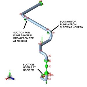
Many times, as stress guys, we come across complicated and long piping layouts to be modeled in CAESAR II. These may include parallel pump suction/discharge piping, inlet/outlet piping to/from multiple Coke Drums, and outlet piping from two sides of Fired Heaters.
In the majority of the cases, we found that these parallel paths are either absolutely similar, or mirror each other, with respect to pipe length, fittings, valves, supports and hangers, and other details.
In case we go for modeling these parallel or similar paths separately, not only it consumes additional man-hours, there is always a chance of human error.
Thus, if we can identify the lines having similar or mirror geometry, we can model once, and make copies as required.
Even in case, the paths are similar but not parallel, e.g. discharge lines two groups of pumps, seating orthogonally to each other, we can re-use the portion of the model with suitable rotation of duplicated path. Now, we will cite the example of a pair of process pump suction lines.
Fig. 1
Now, we need to model another suction branch from Node 50, by duplicating Elements between Node 70 to Node 220.
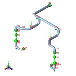
Now click on ‘List Input’, and select the Elements between Node 70 to Node 220. Then right-click, select ‘Block Operation’, and then ‘Duplicate’.
Fig. 2
Now, choose the option as ‘Mirror Y-Z’ (this needs to be assessed beforehand). And select ‘Insert Copied Block’ as ‘At End of Input’. Put Node increment as ‘150’, so that Node 80 would be incremented to 230 and so on, and finally Node 220 would be incremented to 370.
Fig. 3
Now, at Row 22, change the ‘To’ Node No. to 50.
Fig. 4
Now, the complete model with Suctions for both Pump A and Pump B is ready for analysis.
Fig. 5
Note: This method would transfer all the elements and properties of the first branch, except Node Names and Line Numbers, which the user needs to update manually.
A Combined Cycle Power Plant (CCPP) is a highly efficient type of electricity generation facility that combines two distinct thermodynamic cycles, namely the Brayton cycle and the Rankine cycle, to maximize energy conversion and overall efficiency. This innovative approach to power generation has become increasingly popular due to its ability to produce electricity with lower emissions and higher fuel efficiency compared to traditional power plants. In this comprehensive guide, we will explore every aspect of the Combined Cycle Power Plant in detail, covering its components, working principles, advantages, disadvantages, and more
What is a Combined Cycle Power Plant?
A Combined Cycle Power Plant (CCPP) is a type of power generation facility that utilizes a combination of two thermodynamic cycles to generate electricity efficiently. It incorporates a gas turbine cycle, known as the Brayton cycle, and a steam turbine cycle, known as the Rankine cycle, in a coordinated manner. This combination allows for the efficient utilization of high-temperature exhaust gases from the gas turbine to produce steam, which drives a steam turbine to generate additional electricity. CCPPs are renowned for their high thermal efficiency, which makes them an attractive choice for both baseload and peaking power generation.
A Combined cycle power plant is a highly efficient power generation unit. They are the cleanest and most efficient. The process of combined cycle power generation recovers the temperature from the exhaust gas and utilizes that heat in power generation. It is believed that they produce around 50 percent more electricity from the same fuel consumption. So combined cycle power plants are economical as compared the conventional ones.
Introduction of Combined Cycle Power Plant
The development of CCPPs can be traced back to the mid-20th century. The concept of combining gas and steam cycles to enhance power plant efficiency gained significant attention during the energy crisis of the 1970s. Early CCPPs were relatively small and used for specific industrial applications. However, advancements in gas turbine technology, materials, and control systems have made CCPPs more widely applicable for large-scale electricity generation. Today, they play a pivotal role in meeting the world’s increasing demand for electricity while addressing environmental concerns.
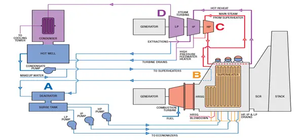
In a combined cycle power plant (Fig. 1), electricity is produced by two turbines; a gas turbine, and a steam turbine. The gas turbine is operated by the combustion products of the fuel (Brayton cycle), while the steam turbine (Rankine cycle) is operated by the steam generated by HRSG from the heat content of the exhaust gases leaving the gas turbine.
The name combined cycle power plant is provided because the gas turbine operates according to the Brayton cycle and the steam system operates according to the Rankine cycle. So, two cycles generate power combinedly. Fig. 1 below shows a schematic overview of a combined cycle power plant.
Fig. 1: Schematic of Combined Cycle power plant
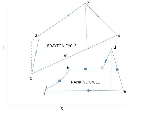
The gas turbine cycle works in the high-temperature region. Once the work is produced by the Brayton Cycle, the exhaust heat is routed to the nearby steam turbine for producing extra power by the Rankine cycle. Fig. 2 below shows both Brayton and Rankine Cycle.
Fig. 2: Brayton & Rankine cycle for Combined Cycle Power Plant
Components of a Combined Cycle Power Plant
The main components of a combined cycle power plant are
a Gas Turbine (GT)
an HRSG or heat recovery steam generator
a Steam Turbine and
other accessories or associated items.
Gas Turbine
A gas turbine in a combined cycle power plant converts natural gas or fluid into mechanical energy. A simple gas turbine has three sections: a compressor, a combustor, and a power turbine. It operates on the Brayton cycle principle. The working philosophy of gas turbines is simple. The compressed air is mixed with fuel and then burned under constant pressure. Then the hot gas flows through the turbine to produce work. Here’s how it works:
Compression: Air from the atmosphere is drawn into the compressor, where it is compressed to a high pressure and temperature. This compressed air is then directed into the combustion chamber.
Combustion: In the combustion chamber, fuel is injected and ignited, producing high-temperature, high-pressure exhaust gases. The combustion process releases a significant amount of thermal energy.
Expansion: The hot exhaust gases flow through a turbine, causing it to spin. This spinning motion drives the gas turbine’s shaft, which is connected to a generator, thus converting the thermal energy into mechanical energy.
Exhaust: After passing through the turbine, the exhaust gases exit the gas turbine at a lower pressure and temperature, typically at a velocity high enough to drive the compressor, creating a closed-loop cycle.
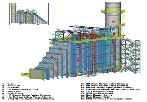
HRSG or Heat Recovery Steam Generator
The HRSG (Fig. 3) receives the exhaust gases from the Gas Turbine discharge. The exhaust gas, flowing in the counter-flow direction with respect to the steam/water coils, cools down by transferring heat to the steam/water. The flue gas temperature at the stack is about 110°C. Lower temperatures of 93°C can be used if the fuel gas is very clean and sulfur-free.
The HRSG is similar to a heat exchanger in which the shell side carries the flue gas and the tube side carries steam or water. It also has the characteristics of a boiler because there are steam drums, where the generated steam is separated from boiling water before entering the superheaters.
The HRSG can be horizontal or vertical, according to the direction of the flue gas path. The horizontal HRSGs are the most common. The vertical ones mainly are limited to installations where space is very tight.
HRSG Pressure and Temperature Levels
The HRSG can have one, two, or three pressure levels according to the size of the plant.
For plant sizes of 200–400 MW, the pressure levels used are HP, IP, and LP.
Plants down to 30–60 MW usually have two pressure levels (HP and LP),
Smaller units only have one pressure level. Sometimes, with three pressure levels, the LP section produces the steam needed for deaeration only.
The following tube banks are used for each pressure level (starting from the GT exhaust): 1) steam superheaters, 2) evaporator, and 3) economizer.
Fig. 3: HRSG
HRSG Design Features
Sometimes empty module is inserted in the flue gas ducts of large HRSGs where the flue gas temperature is 350–380°C, which can be used in the future for the installation of a selective catalytic reduction unit for further NOx abatement. Sometimes, a spool piece for the future addition of an oxidation catalyst for CO abatement is included for the same purpose as the SCR and located in the same position.
The pressure drop across the HRSG on the flue gas path is in the range of 200–375 mm water column. This pressure drop is the back-pressure of the GT and influences its generated power and efficiency by 1 and 2%, respectively. The HRSGs are provided with a set of motor-operated valves that are installed in the steam and water lines.
The feedwater inlet lines to the economizers are also provided with on/off shut-off valves. Having these shut-off valves allows the “bottling in” of the HRSG by closing all inlet and outlet lines, thereby keeping the boiler pressurized when the shut-down period is expected to be short. Additional motor-operated valves are used to remotely and automatically operate the drains in the superheaters.
The HRSG also includes a pressurized blow-down tank and an atmospheric blow-off tank and is also equipped with chemical injection pumps to maintain the water and steam chemistry specifications. The HRSG is also equipped with nitrogen connections for purging (dry lay-up) to prevent corrosion in case of long shut-down periods.
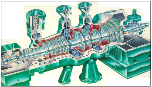
Steam Turbine
Steam turbines in a combined cycle power plant extract energy from the steam and convert it to work, which rotates the shaft of the turbine. The amount of energy that the steam turbine extracts from the steam depends on the enthalpy drop across the machine.
The enthalpy of the steam is a function of its temperature and pressure. As inlet and outlet temperature and pressure are known, one can use a Mollier diagram to determine the amount of energy available. Steam turbine (Fig. 4) sizes range from a few kilowatts to over 1000 megawatts.
Operating Control Modes of Steam Turbine
Steam Turbine operates in three control modes:
Fixed pressure mode– Below 50% load, which corresponds to about 50% of the live steam pressure, the steam turbine will be operated in a fixed pressure mode. In this mode of operation, pressure from the steam generator remains constant and is controlled by the main control In case the steam turbine is not taking all produced steam, the pressure of the steam generator is controlled by the bypass valves.
Sliding pressure mode– When the 50% load is reached the main control valve is fully open. With increasing gas turbine loads the steam turbine will be operated in sliding pressure mode. In this case, the live steam pressure varies proportionally with the steam flow.
Load control– when the generator is synchronized to the grid, its frequency is governed by the grid. The turbine controller maintains the baseload by adjusting the steam flow.
Fig. 4: Steam Turbine
Other Accessories of Combined Cycle Power Plant
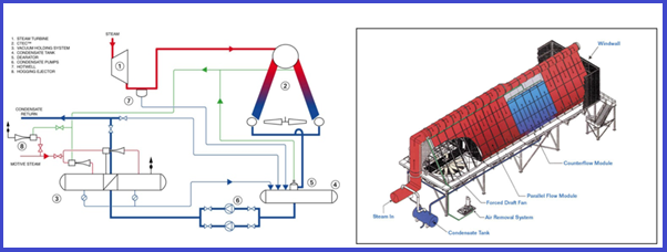
Air Cooled Condenser
The air-cooled steam condenser (ACC-Fig. 5) condenses the turbine exhaust steam or the de-superheated steam from the turbine bypass. The condensate collected in the steam/condensate headers drains under gravity to the condensate tank, from where it is pumped by the condensate extraction pumps to the boiler system on level control.
The turbine back pressure is controlled by fans using pressure transmitters on the ST exhaust. Pressure transmitters protect the ACC in case of overpressure. The control system modulates a number of fans into operation and fan speed and steam isolating valve position to meet the back pressure set point.
Temperature transmitters in the main steam duct protect the condenser against overheating.
Fig. 5: Air Cooled Condenser
Types of Condensing Systems
The selection of the condensing system for a combined cycle power plant varies based on environmental conditions. They are classified into the following categories:
Water-cooled surface condensers and wet condensing system
Air-cooled condensers
Alternative condensing systems
Air Extraction System
The non–condensable has to be evacuated from the condenser before steam can be introduced at start-up (hogging process) and should be continuously removed during normal operation (holding process)
HOGGING PROCESS – For the hogging process, the requirements are to lower the pressure as quickly as possible from the atmospheric pressure (946 mbar(a)) to 250 mbar(a) ) within 30 minutes.
HOLDING PROCESS – Once the vacuum is established and during normal operation, the hogging extraction skid is shut down and only one holding vacuum set continuously removes the non-condensable.
Bypass Stack and Diverter
In some instances, when electric power generation is a must, it should be possible to run the gas turbine in an open cycle and exhaust the flue gas into the atmosphere instead of sending it to the HRSG, regardless of the overall efficiency. This requires a bypass stack and a diverter that closes the path to the HRSG and opens it to the atmosphere through the bypass stack.
The diverter is connected to the GT exhaust duct before the diverging cone of the HRSG, and this implies that the GT has to meet the plant emissions limits, as any SCR in the HRSG is also bypassed. Throttling by the diverter could also be used to control steam generation in the HRSG. This configuration is rare.
The most important characteristic of a well-designed diverter is its ability to completely switch the flue gas from the bypass stack to HRSG, under all operating conditions.
Auxiliary Systems of Combined Cycle Power Plant
Boiler Feed Water Pump:
The LP drum can be used to feed the boiler feedwater (BFW) pumps on level control as explained in the three elements control system. If there are HP and IP sections, the BFW pumps can be multiple-stage centrifugal pumps with an intermediate discharge for the IP section. Automatic minimum flow bypass, a Three-way Yarway valve, on the HP discharge nozzle of the pump, is used for minimum flow protection.
Bypass System:
The superheated steam to the steam turbine is bypassed to the condenser during the start-up, ST shutdown, and load rejection. The bypass arrangement includes
HP bypass from the HP header to IP header (cold reheat side if reheating is implemented)
IP bypass from the IP header (hot reheat side if reheating is implemented) to the condenser.
LP by-pass from the LP header to the condenser.
Each bypass requires a pressure reduction and desuperheating with boiler feedwater or condensate to meet downstream condenser conditions.
Blow Down Tank:
To keep the required steam purity, a small percentage (1–3%) of the water in the steam drums is discharged to continuous blow-down.
For large boilers, there is a pressure blow-down tank into which the HP and IP steam drums drain. In addition, an atmospheric blow-off tank is also provided to receive the water from the blow-down tank plus the drains from the LP drum and the blow-off from the HP and IP drums.
Demineralization Plant:
The water needed for filling the HRSG and as make-up water during normal operation is generated in a demineralization plant. The demineralization plant is usually controlled by its own PLC, which is interfaced with the DCS, but sometimes is controlled directly by the plant DCS system.
The demineralized water is stored in a tank that should be sized sufficiently large to provide water in case of disruption in production. It should also store enough water to supply the quantity needed for pipe blowing in the pre-commissioning stage, without the need for waiting for the production of new water. This consideration can be the basis for sizing the demineralized water storage tank
Closed Circuit Cooling Water:
If an air condenser is used, the closed-circuit cooling water system becomes much smaller, because the amount of water needed in the rest of the plant is a relatively small percentage of that needed for the water condenser. The users of the CCCW are turbine generators, condensate and feed water pumps, sampling systems, etc.
Other auxiliary components of a gas turbine can be
Gear Box
Intercooler heat exchanger
regeneration heat exchanger
supplementary firing system
Start-up philosophy of Combined Cycle power generation plants
The main concern in starting a combined cycle power plant is to avoid thermal stresses to the machines that would shorten their life and produce unsafe conditions. This consideration extends the time for start-up, while economics require that start-up take place in the minimum possible time and with minimum fuel consumption.
Each manufacturer of the main plant equipment sets the requirements for its machine. The process design engineers shall combine these requirements with their own to arrive at start-up procedures that will minimize the overall start-up time.
The gas turbine is the fastest starting component in a combined cycle power plant. It takes about less than 10 min to get to the synchronized speed.
HRSG of the combined cycle power plant has thermal inertia and rapid heating may result in high thermal stresses which would affect the life of the HRSG. In HRSG, the HP steam drum is most vulnerable to the build-up of thermal stresses if heating is done rapidly. To avoid this possibility the drum is heated in a controlled manner. The magnitude of the thermal stress development depends on the temperature difference which in turn depends on the material, operating pressure, and thickness of the material.
The temperature difference can be effectively controlled by controlling the pressure inside the drum. If a certain temperature difference is close to the design limit it can be controlled at that level by holding the pressure constant. This is indicated by the constant pressure/temperature line.
The heat input is controlled by operating the GT at a reduced load. A gas-side bypass system, which diverts part of the hot GT gasses to the atmosphere is also used to control the heat input to the boiler.
HRSG start-up without gas bypass damper:
The GT and the HRSG of a combined cycle power plant are connected directly without a bypass damper if the power production is to be maximized and there is no requirement for simple cycle operation. It is possible under certain circumstances to run the HRSG ‘dry’ or produce no steam while the GT is operating. Usually, this requires additional constraints in the design and limitations of GT exhaust temperature.
HRSG start-up with gas bypass damper:
The damper can control the gas flow to the HRSG, part of the gas at operating temperature passes through the HRSG. Thus the amount of steam production and the drum pressure can be maintained at the required level by allowing the required amount of gas through the HRSG
Most of the damper systems have limited turndown capability. Therefore venting or bypassing the steam is still needed, though the capacity and time required may be less. The bypass damper must be utilized when there is a need to run the plant in a simple cycle.
The heating of IP and LP drums and the steam production in these drums is not of much concern because they are operated at low pressures and have low capacities.
Steam turbine warm-up:
The steam turbine of a combined cycle power plant has the most mass and has components with much thicker cross-sections. Therefore, it needs the longest warming uptime. Warm-up generally takes three to five hours. Since the Steam Turbine start-up takes longer, the HRSG needs to be maintained at the low load operation for a much longer time if the steam is supplied for warm-up.
Various combinations of start-up scenarios are feasible for a power plant. These are mainly determined by the temperature of each of the components at the start-up time. For instance
a ‘cold’ state means that the component is at room temperature, having been down for a considerable time, usually days.
A ‘warm’ start results when the unit is down for a few hours and most of the heat is not lost.
A ‘hot’ start occurs when the unit is shut off for a very short period of time after operating for a considerable time at full load.
Fuel for Combined Cycle Power Plant
Combines cycle power plants can be fuelled using the following:
Natural gas
Crude oil
Bunker fuel
Distillate and
Residual oil
However, Fueling with crude or residual oil calls for extra capital spending for fuel treatment equipment. Also, the operation suffers due to additional operating costs for additives to counteract contaminants present. The type of fuel and mode of operation decide the maintenance intervals and the amount of maintenance work required.
Advantages of Combined Cycle Power Plant
The major advantages of a combined cycle power plant are:
Increases overall plant efficiency: plant efficiency increases by 50% or more
Reduced investment cost: Investment cost is reduced by 30% as compared to a conventional steam power plant.
Reduced water requirement.
Phased installation is possible.
Fully Automatic Operation, so less staff is required.
Lower environmental impact.
Highly reliable and Flexible
Can start up and shut down quickly.
Lower maintenance and installation costs.
The lowest global warming effect
Lower construction time.
Disadvantages of Combined Cycle Power Plant
Some disadvantages of a combined cycle power plant are:
Technologies are complex and expensive which increases the initial investment.
The efficiency of part-load demand is poor.
To operate at high temperatures and pressure, special metals are required.
Limited fuel switching capability.
Applications and Types of Combined Cycle Power Plants
Base Load and Peaking Plants:
CCPPs can serve as base load power plants, providing a steady and reliable source of electricity, or as peaking plants, responding to periods of high electricity demand. The flexibility of CCPPs allows them to adapt to different operational roles based on grid requirements.
Single-Shaft and Multi-Shaft Configurations:
CCPPs can be designed with single-shaft or multi-shaft configurations. In a single-shaft design, both the gas turbine and steam turbine share a common shaft and generator. In a multi-shaft configuration, separate generators are used for the gas and steam turbines, providing greater operational flexibility and control.
Cogeneration and Combined Heat and Power (CHP):
Some CCPPs are configured for cogeneration or combined heat and power (CHP) applications. In these setups, the waste heat from the HRSG is not only used to drive a steam turbine but also for industrial processes or district heating, maximizing overall energy efficiency.
Future Developments and Innovations
Advanced Gas Turbine Technologies:
Ongoing research and development efforts are focused on improving the efficiency and performance of gas turbines used in CCPPs. This includes advancements in materials, aerodynamics, and combustion technology.
Integration with Renewable Energy:
CCPPs can be integrated with renewable energy sources, such as solar and wind, to provide a more reliable and stable electricity supply. This combination of fossil fuel-based and renewable energy helps mitigate the intermittency of renewables.
Hybrid and Integrated Energy Systems:
CCPPs are increasingly being incorporated into hybrid and integrated energy systems that combine various energy sources and technologies, including energy storage and grid management solutions. These systems aim to enhance grid resilience and optimize energy generation.