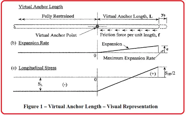
A pipeline restrained by fixed anchors will experience a series of stresses including longitudinal, bending, and axial. Virtual anchor lengths are taken as the distance required for the frictional force provided by the soil surrounding the pipe to equal the forces applied by thermal/ pressure expansion and the soil’s resisting friction per unit length of pipe.
Anchors are placed strategically along the pipeline to help prevent movement. Unrestrained pipeline movement can cause damage to the connecting piping and equipment. The length of piping required to form the virtual anchor is known as the active length. It must be noted that the force required to fully restrain a pipe is not a function of its length. Factors that influence the required force to restrain the pipe include temperature, pressure, and percentage strain within the pipe.
Soil provides a constant frictional force along a buried steel pipeline. The magnitude of the frictional force depends on the burial depth, pipe weight, soil density, and coefficient of friction between the soil and steel. Therefore, starting from a free end, the total restraint exerted by the soil on the pipe gradually increases until it reaches the fully restrained load at the virtual anchor. At this point, the naturally occurring forces are balanced with a restraint point. Similarly, moving along the pipe away from the virtual anchor, the pipe expansion becomes gradually minimized until a point of zero expansion is reached indicating the pipe is fully held in place.
Axial expansion is calculated by taking the average of the full axial restraint at one end of the pipe and zero restraint at the opposite end of the pipe. When compared to above-ground piping, the total axial expansion at the free end of a buried pipeline is half of the calculated value for a similar scenario involving the above-ground pipe.
In reality, most pipes do not have a totally free end but have some resistance due to soil restraint as the pipe exits the ground and from the connection to above-ground piping. This acts to reduce the expansion at the ‘free’ end. Soils with lower friction resistance or pipes with less depth of cover have longer active lengths and thus have greater expansion at the free end.
Fig. 1: Visual Representation of virtual Anchor Length
Virtual Anchor Length Calculation Sequence
Variables Required for Virtual Anchor Length Calculation
Pipe Properties
The following Pipe Parameters are required for Pipeline Virtual Anchor Length Calculation:
FEx(T) = Expansion Force Due to Temperature Change
FEx(P) = Expansion Force Due to Pressure
FP = Force due to Pressure
FF = Frictional Force
La = Anchor Length
Virtual Anchor Length Calculation
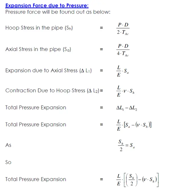
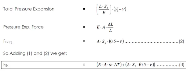
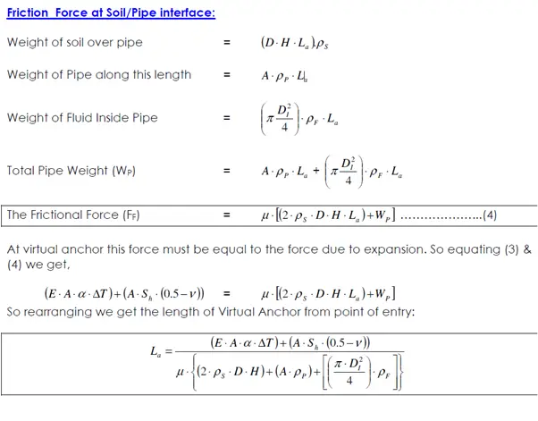
Theoretically, there will be pipe movement from the entry point due to thermal expansion. Also, an expansion will be there due to the pressure. Opposing these two is the frictional force between pipe and soil. Let us find these factors first:
Expansion Force due to Temperature Change:
Expansion Force due to Change in Temperature will be:
FEx(T) = E × A×a × DT ………………………………..(1)
Few more Pipeline-related useful Resources for You.
A water hammer is a hydraulic shock that occurs in a piping system when a fluid (usually water) is suddenly stopped or forced to change direction. This sudden change in the fluid’s momentum can create a pressure surge that travels through the piping system, causing a loud banging noise, and vibrations, and potentially damaging the system.
Water hammer occurs when a valve is closed too quickly, causing the fluid to stop abruptly, or when the flow direction of the fluid is suddenly changed. The pressure surge created by the water hammer can be many times greater than the normal operating pressure of the system, potentially causing pipes to burst or fittings to fail.
Water hammer can be prevented or minimized by designing the piping system with gradual changes in direction and using properly sized piping and fittings. Additionally, valves should be closed slowly to prevent sudden changes in the flow direction, and air vents or expansion tanks can be installed to absorb pressure surges.
Water hammer can also be controlled by using pressure relief valves or surge tanks to release excess pressure before it can cause damage to the system. It’s important to address the water hammer promptly to prevent damage to the piping system and ensure safe and efficient operation.
It is well-known that water hammer is caused in a piping system by sudden closure or opening of the valves or due to pump trips. During those events, the pressure increases to a huge extent and that causes an unbalanced load in the piping system which is known as the Water hammer load. All these loads are created due to water hammer acts in the changes in directions and can be of sufficient magnitude to cause the piping system failure. So, during the design phase, water hammer analysis must be performed to calculate the water hammer loads and design piping and support systems to avoid failures. In this article, we will discuss the pipe stress analysis methodology for water hammer loads.
In piping systems, sudden changes in flow cause pressure unbalanced forces between elbows, valves, tees, reducers, and other inline components. These forces damage the piping system when it is not properly designed to accommodate them.
The main advantage of using PASS/START-PROF + PASS/HYDRO SYSTEM is that the 3D piping model can be easily converted between these software packages both ways.
3D piping model from PASS/START-PROF can be converted into the 3D piping model in PASS/HYDRO SYSTEM, then generate 3D water hammer loads for all nodes at certain moments of time (not only just in one node!) and pass it directly into stress analysis software PASS/START-PROF automatically (not manually!).
PASS Suite START-PROF + HYDRO SYSTEM allows us to model it very easily, just in several clicks, and help to find a way to reduce water hammer damage to the piping system. Let’s study how to perform stress analysis of the piping system from water hammer loads.
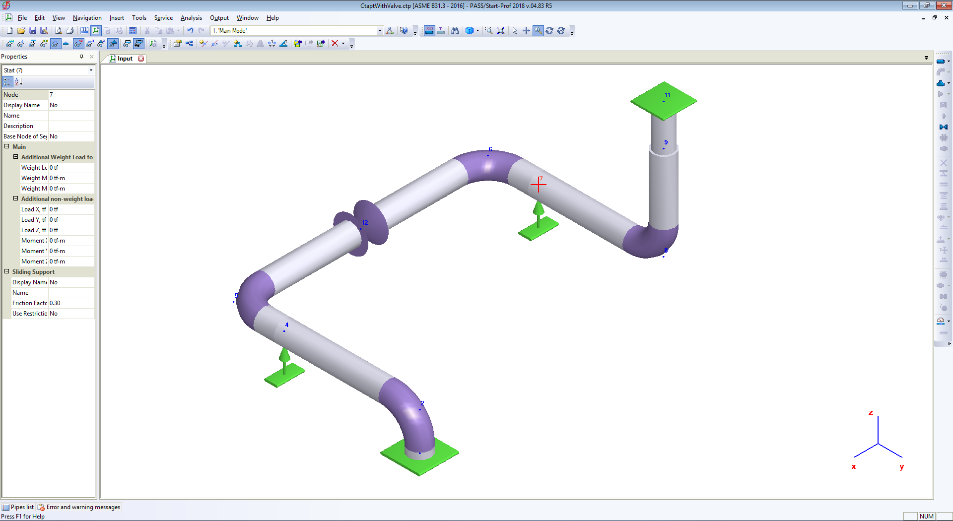
The simple piping system created in PASS/START-PROF software is shown below screenshot:
Simple Stress System for Water hammer load explanation
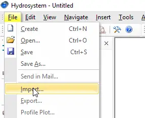
After saving the PASS/START-PROF file, we can open it using the PASS/HYDRO SYSTEM software.
Importing the file in HYDROSYSTEM
Set pressure 0.15 MPa at node 1, and 0.16 MPa at node 11
Inputting for Water hammer Analysis
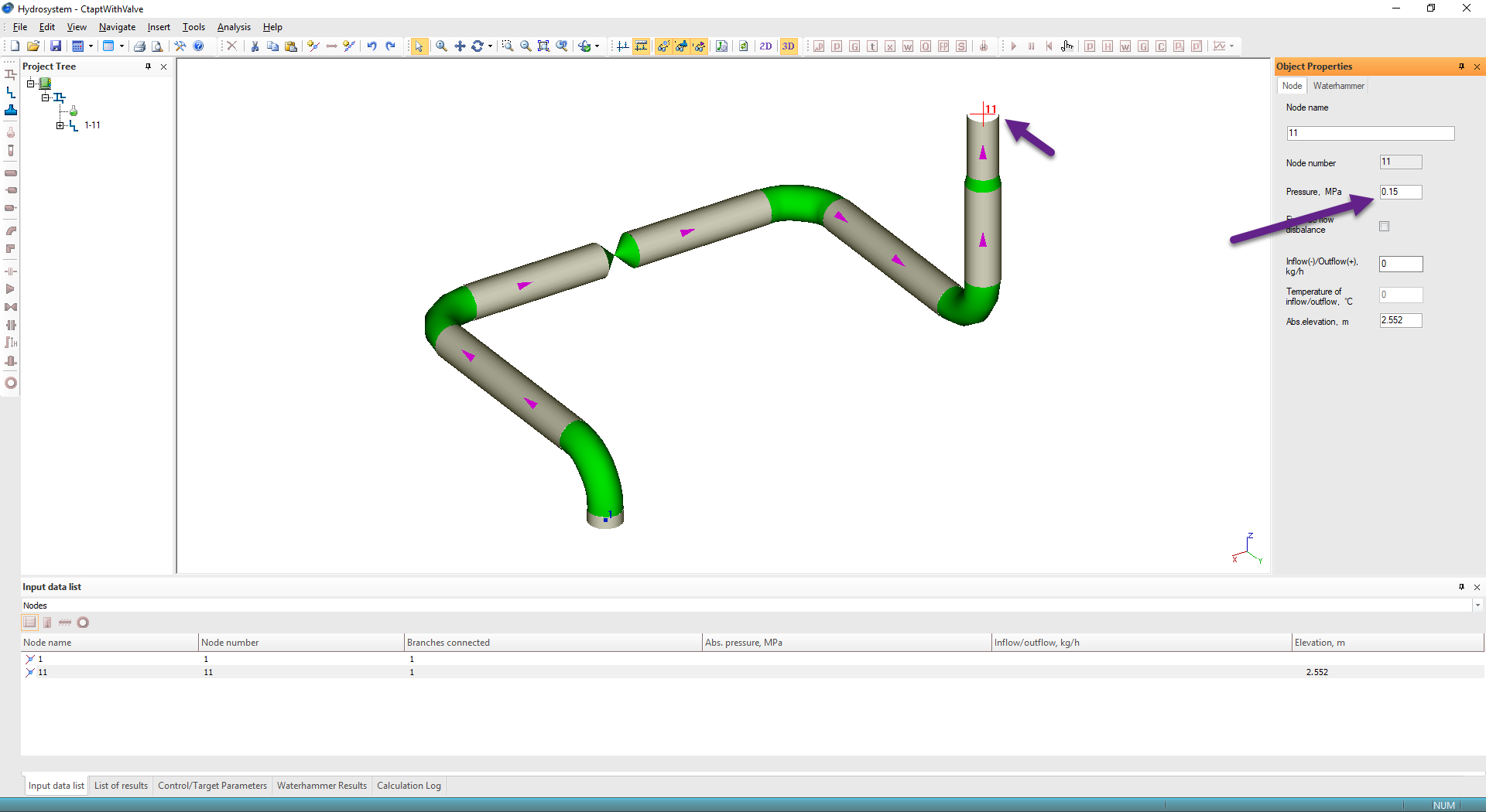
Choose water steam library
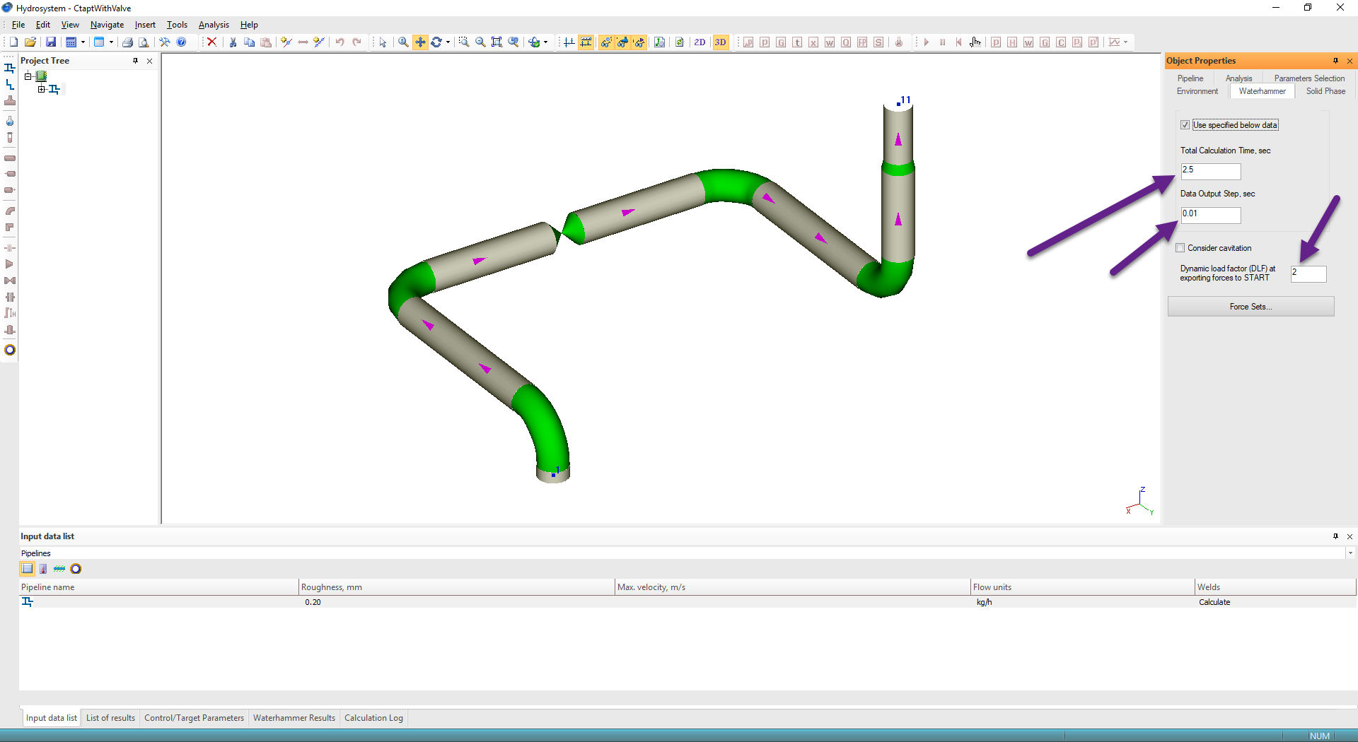
Choosing Object properties for Water Hammer Analysis
Define the period of surge analysis 2.5 sec, data output stem 0.01 sec, and dynamic load factor DLF=2.0.
Entering Dynamic parameters for Water hammer loads
Select Valve in node 12 and in the “Waterhammer” tab set that valve is immediately closed.
Setting the valve for Water Hammer Analysis
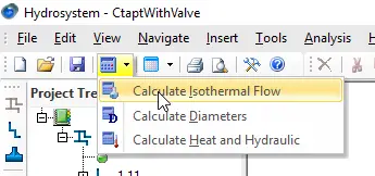
Run Isothermal Flow analysis
Calculating isothermal Flow
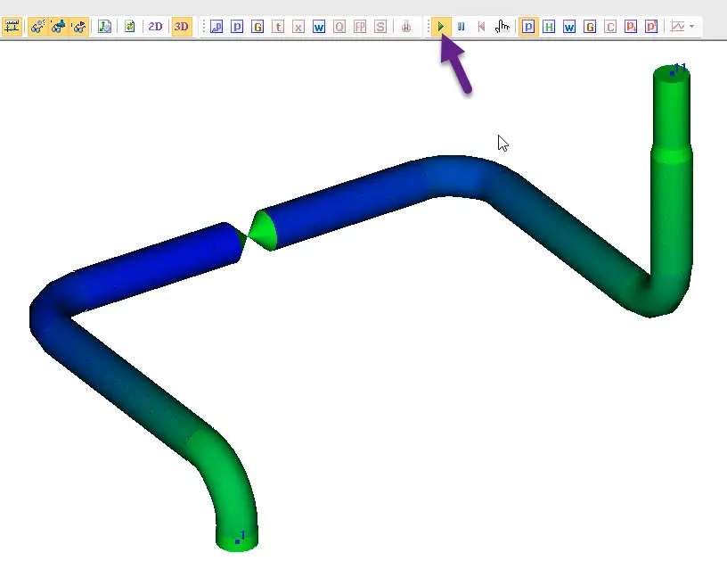
Run water hammer analysis
Running the Water Hammer Analysis
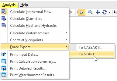
After that export unbalanced pressure forces into (.ctpf) file. Also, HYSROSYSTEM allows exporting data into (.frc) file that can be opened by CAESAR II.
Exporting Unbalanced pressure forces into FRC file
(.ctpf) file contains forces multiplied by DLF factor for all nodes in piping models at several most dangerous moments of time. The most dangerous moments of time is found automatically by HYROSYSTEM software.
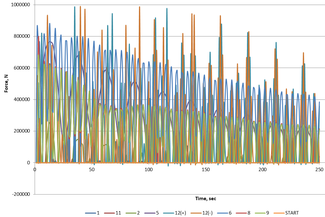
Force vs Time Plot for water hammer loads
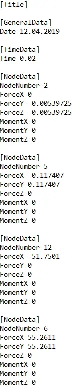
This is the (.ctpf) file structure
Structure of CPTF file
This means, that PASS/HYDROSYSTEM generates unbalanced pressure loads for all nodes in the piping system at a certain moment of time.
Water Hammers loads with respect to Time
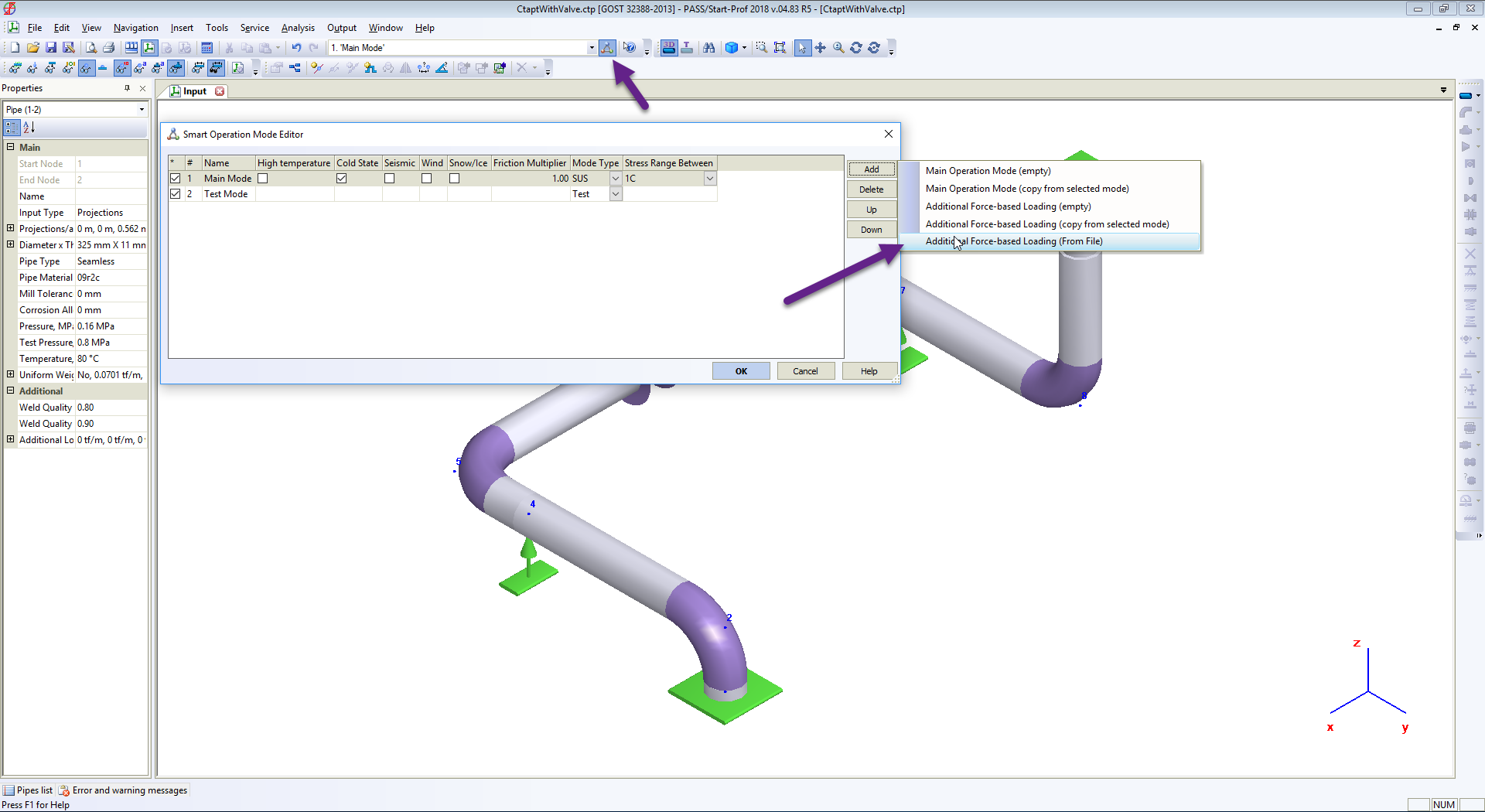
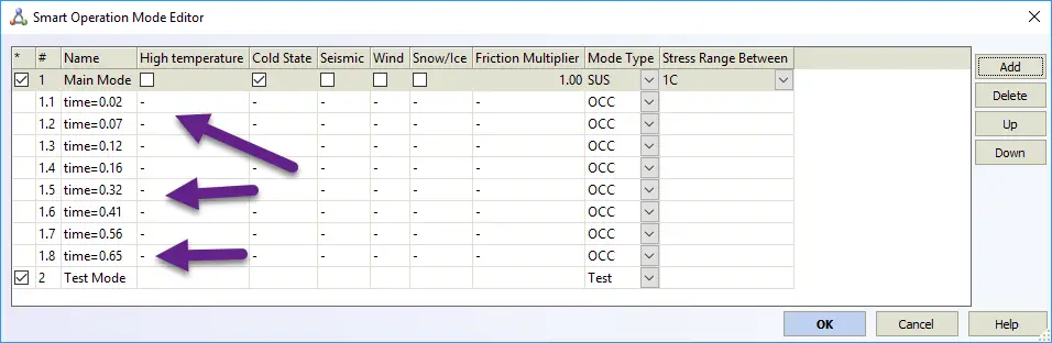
Now open PASS/START-PROF, open Operation Mode Editor and import waterhammer forces into first operating mode.
Importing water Hammer loads
Eight additional force-based load cases are imported from the file
Creating additional load cases for water hammer analysis
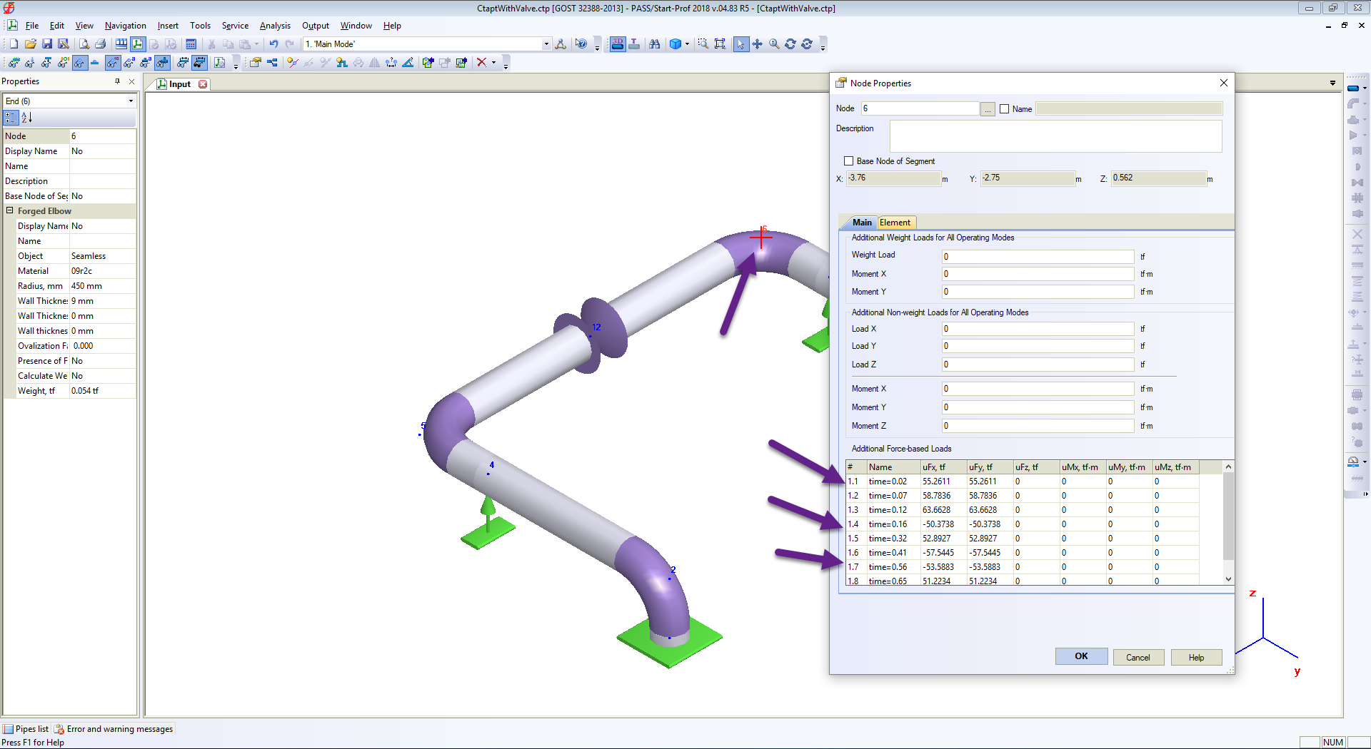
You can check the force values at any node properties
Water hammer loads at nodes
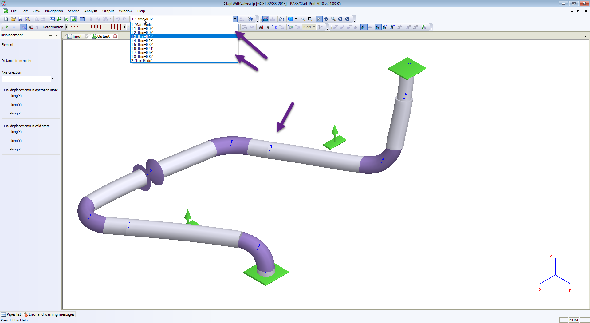
Now run piping stress analysis and see results
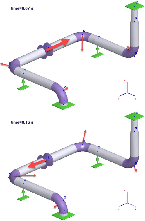
Deformed Shape at any moment of time
Deformed shapes due to water hammer loads
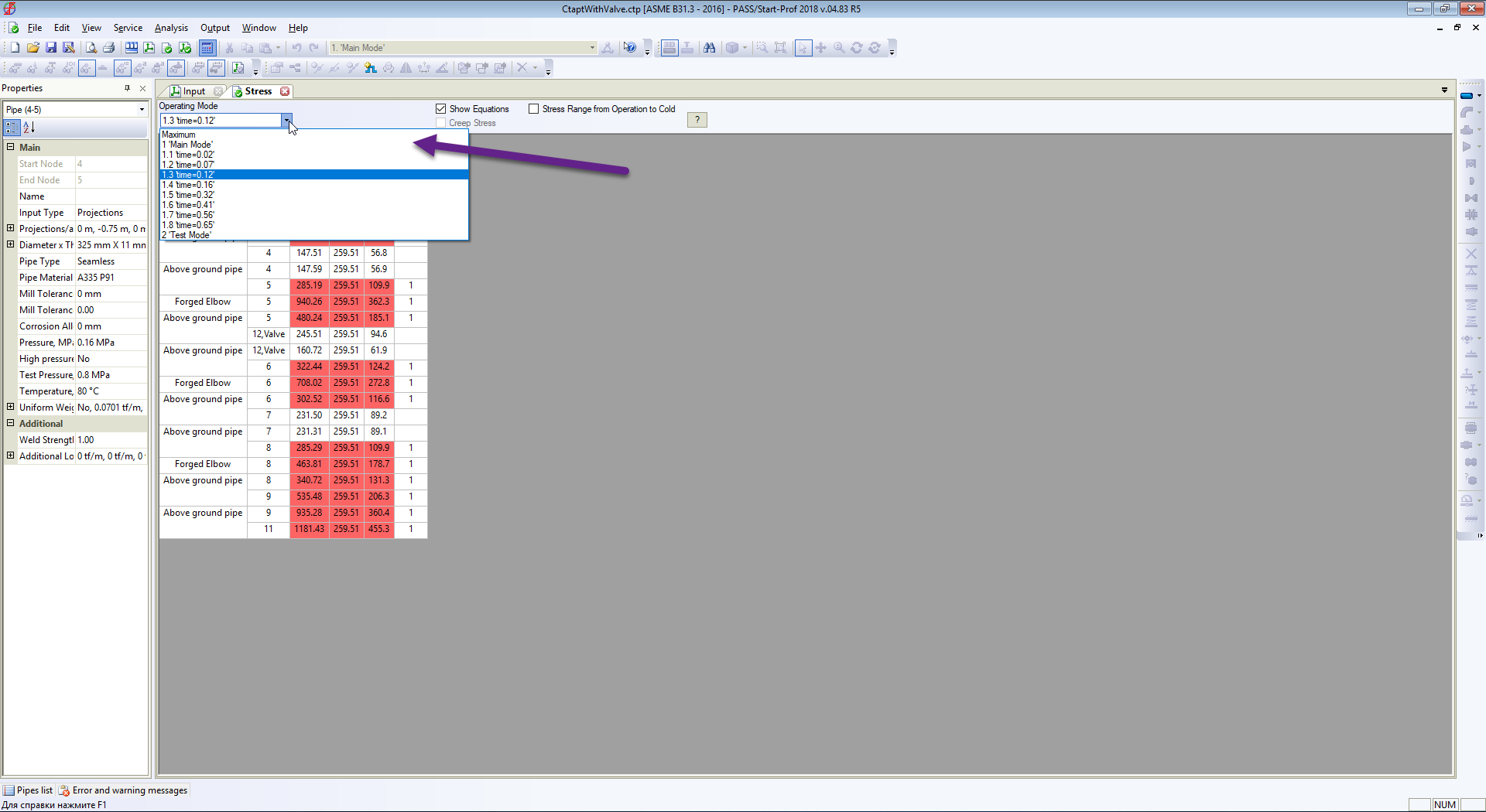
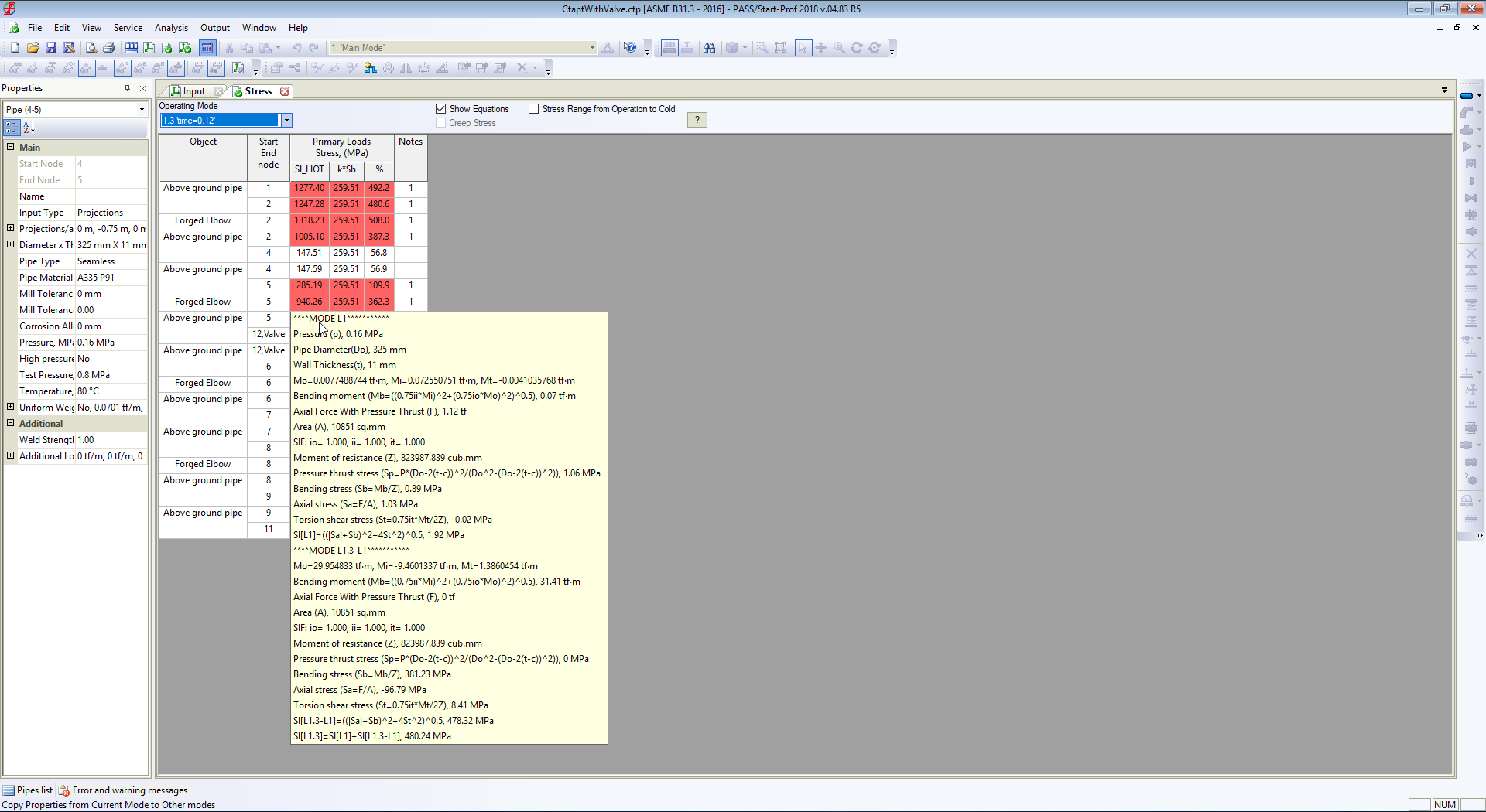
Stress table at any moment or time
Stress Table during water hammer analysisDetailed stress value during water hammer analysis
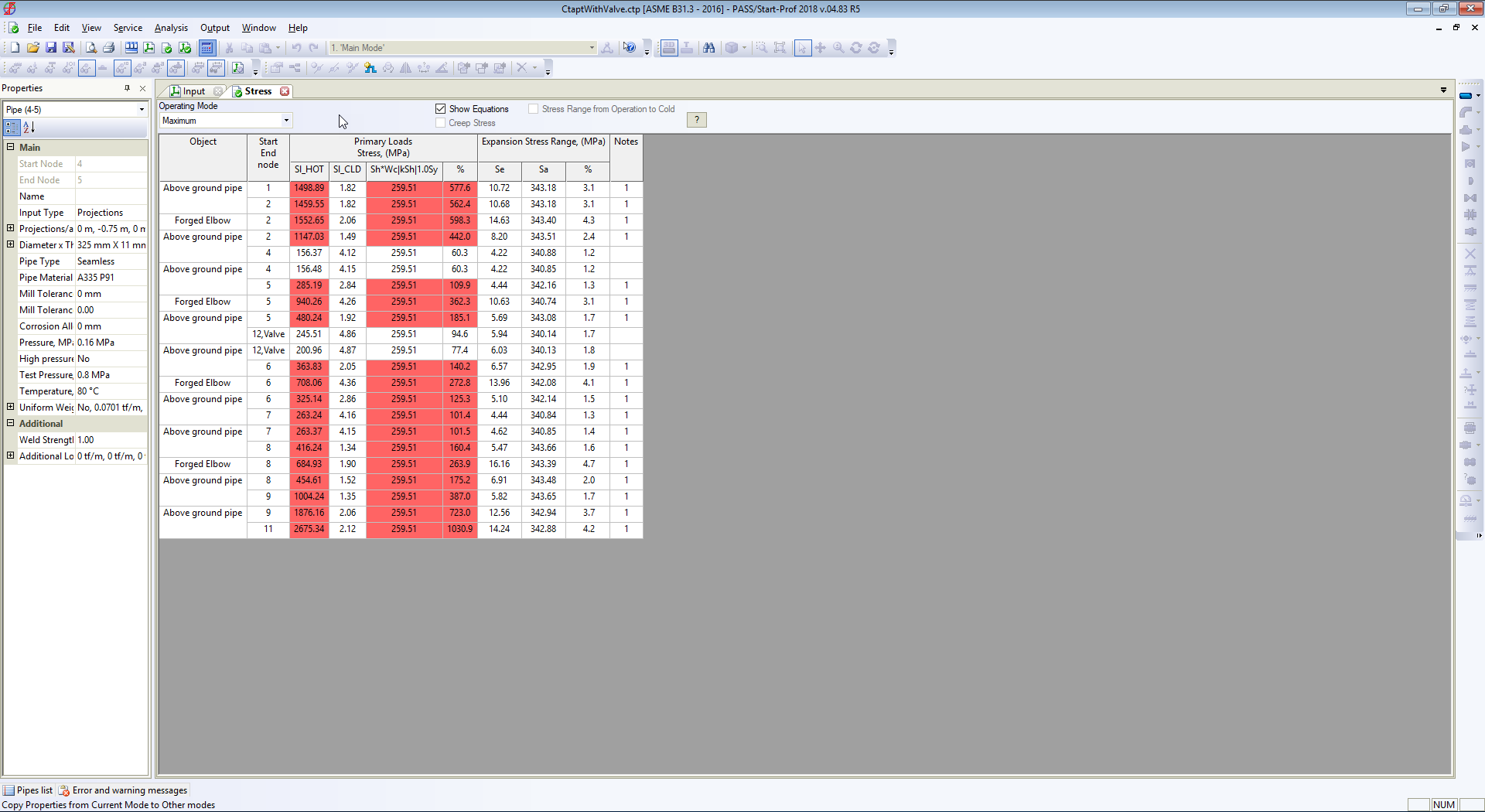
And maximum stresses from all load cases (static and all moments of time during waterhammer)
Maximum stresses
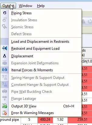
The same table can be checked for displacements, support loads, flange leakage, expansion joint deformations, etc.
Output results
Watch the following video with detailed analysis process described above:
Video Tutorial for Pipe Stress Analysis from water hammer loads
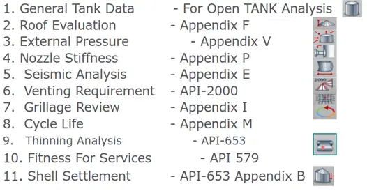
Designing storage tanks are a critical activity. Various parameters need to be considered during design. In recent times the design of storage tanks is automated using various software. In this article, we will explore oil storage tank design methodology using the software “TANK”, developed by Intergraph (Now Hexagon).
What is Intergraph tank?
Intergraph TANK is a comprehensive, easy-to-use software package for the design, analysis, and evaluation of oil storage tanks. It provides users with quick and accurate designs for new tanks and evaluations of existing tanks.
TANK performs calculations in accordance with the latest API Standards 650, 620, and 653. Analysis can also take into account wind, seismic and settlement conditions plus calculate air venting requirements to API 2000 Section 4.3.
Material Database for Above-ground Storage Tank Design
The program includes the following material databases:
TANK has many databases integral to the package which make it easy to select standard data for accurate analysis. A number of US and international structural steel databases are provided.
Apart from this, the user can edit or customize the material properties as per the project requirement.
This will be the starting point of every tank that you analyze.
It defines the diameter, liquid specific gravity and liquid height, any small internal pressure, materials of construction, and the number of shell courses in the cylindrical shell.
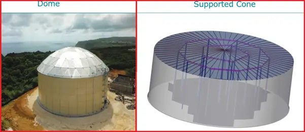
As the name suggests, all the details about the roof are entered here. The types of roofs available for analysis are:
Supported cone
Rafter supported cone
Cone
Dome
Umbrella
The real power of the TANK is calculating the roof and its supporting steel support structure automatically.
Design of Storage Tanks for External Pressure– Appendix V
Here we provide minimum requirements for tanks that are designed to operate with external pressure (vacuum). So with the help of this parameter how we can evaluate the external pressure capacity of the tank.
Storage Tank Nozzle Stiffness- Appendix P:
Where nozzles are subjected to mechanical loadings and temperatures that differ from the shell temperature where differential expansion takes place, Tank will evaluate the stresses in the nozzle to shell junction.
Intergraph Tank Allows you to specify up to fifteen tank nozzles. The data specification can include external piping loads from a pipe stress analysis, if available.
When you select API 650 as the API Design Code in General Tank Data, the software uses the data acquired from this dialog box to implement the rules of API 650, Appendix P.
When the tank temperature value in General Tank Data is changed, the software updates the Modulus of Elasticity and Expansion Coefficient values automatically.
If you check Use PVP-1279, TANK uses an alternate method to compute the nozzle stiffnesses.
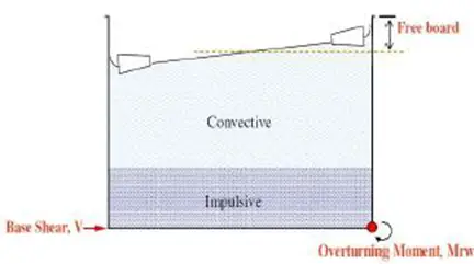
Storage Tanks may have to withstand seismic disturbances in the normal course of their service life. California and Japan are seismically active areas, and the accelerations to which the tank may be subjected must be built into the tank at the design stage before construction. Appendix E of API 650 addresses this aspect of design. Here will see what happens when the vessel has to slurp liquid inside after a seismic disturbance and how we can get shear resistance force, combined hoop stress, and required freeboard value.
Allows you to define the measured settlement of up to 40 points around the tank shell circumference.
With the help of this, we can determine the optimum cosine curve which most closely represents the user’s measured values of shell settlement. After the cosine curve is known, the out-of-plane settlement and out-of-plane deflection can be determined.
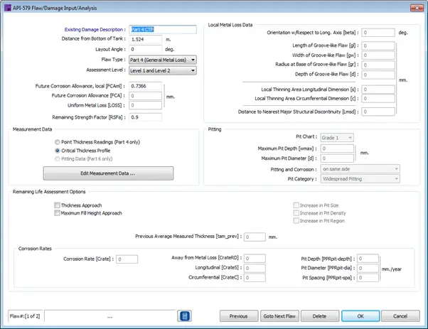
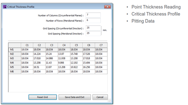
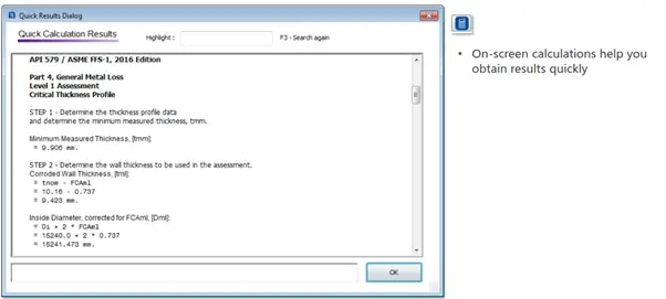
API 579 Analysis Capability Added
In this version, they added calculation per API 579 for analyzing corrosion and flaws for Tanks that have been in service.
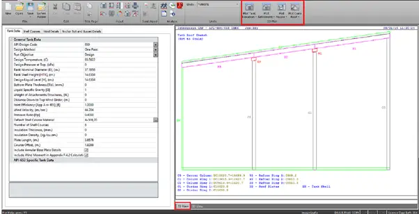
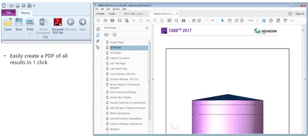
Input spreadsheet and 2D graphics interface:
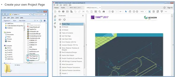
User Definable Project Page:
One Click to Create a PDF of all Reports:
This presentation is prepared by Mr. Deepak Sethia who is working in Image Grafix Software FZCO, the Hexagon CAS Global Network Partner in the Middle East and Egypt. He has extensive experience in using Caesar II, TANK, and PV Elite software and troubleshooting.
Jacketed Piping: Definition, Types, Design Considerations, and Stress Analysis
Jacketed piping is a specialized engineering solution used in various industries to transport fluids that require precise temperature control, such as chemicals, food products, and pharmaceuticals. This complex system combines two distinct pipes: an inner or core pipe that carries the process fluid and an outer or jacket pipe that contains a separate heating or cooling medium. Jacketed piping systems are designed to maintain the desired temperature of the process fluid throughout its journey, ensuring product quality and process efficiency. In this comprehensive guide, we will delve deep into every aspect of jacketed piping systems, covering their components, design considerations, applications, advantages, and challenges.
What is a jacketed Piping?
Jacketed piping is required to transport highly viscous fluids having very low flowability. The jackets usually provide temperature to the core pipe so that the flowability of the fluid inside the core is maintained. The jacketed piping system consists of two pipes of different sizes. The larger pipe covers or jackets the smaller size pipe. Jacketed piping is often referred to as jacketed pipe or jacketed tubing.
Components of Jacketed Piping
Jacketed piping consists of four main components. They are:
Core Pipe: This central smaller-sized pipe of a jacketed piping system that carries the fluid from one point to the other.
Jacket Pipe: This is the larger size pipe that carries superheated steam to maintain the temperature of fluid flowing in the core pipe.
Steam Feeder: This is a tapping connection in the Jacket pipe to provide a path for the steam inlet or outlet.
Spacer/ Guide Plate/ Spider: Spacers shall be provided for supporting the core pipe from the jacket pipe and to ensure a uniform gap between the core and jacket pipes. The detailed dimensions and design of the spacer shall be as the design guide of jacketed piping prepared by the layout team. Stress engineer to follow spider spacing chart while analysis.
Types Of Jacketed Piping
Depending on the nature of the jacket pipe over the core pipe, two types of Jacketed Piping are found; Continuous jacketing and Discontinuous jacketing.
Continuous Jacketing: In this type of piping all piping components including the straight lengths of pipe, fittings, flanges, valves, and branch connections are fully covered by the jacketed pipe.
Discontinuous Jacketing: This type of Jacket pipe consists of jacketing of only straight lengths of the core pipe. Here Branch connections, elbows, Tees, other Fittings, and Valves are not jacketed.
Applications Of Jacketed Piping
Jacketed piping is not used widely and has got some limited applications. This type of piping is only required where a certain temperature needs to be maintained throughout the transportation of fluid from one point to another. Some of the typical examples of jacketed piping are:
To transport molten Sulphur through pipes in a sulphuric acid plant.
To convey cryogenic liquid oxygen in the oxygen generation unit.
Jacket piping can also be used to stop the piping network from getting frost.
To maintain fluidity throughout the piping network in the vegetable oil manufacturing plant
To keep the pipeline system warm when passing through cold areas.
To stop choking of pipes because of extremely cold temperatures in a Bulk career merchant ship.
Design Consideration for Jacketed Piping Systems
Jacketed piping systems are highly complex systems as compared to the usual process piping due to their double-walled piping network. So, these types of piping networks require special consideration during the engineering, designing, and execution phase. Some of the design points are mentioned below:
Fluid Pressure: The core pipe will be subjected to both internal and external pressure. So the thickness of core piping must be designed for both pressure considerations. Also, It is preferable that the fluid flowing in the core pipe has lower operating pressure as compared to the jacket pipe. This will ensure that the product can be contained in the jacket for any unforeseen failure in process core piping.
Feeder Port Location: The feeder inlet and outlet port locations vary as per the media in the jacket pipe. For Liquid medium in the jacket pipe, the inlet feeder port should be located at the lowest point and the outlet should be at the highest point. This will ensure the jacket is filled with media before leaving the system.
While for gaseous media in the jacket, the Inlet port of the feeder should be at the highest point and the outlet point should be at the lowest point.
Slope: A jacketed piping system is usually installed with some piping slope to help in the fluid flow of the core pipe. This will also ensure the complete drain out of process fluid from the core pipe.
Fluid Flow Direction: The fluid flow direction inside the core and jacket pipe preferably be opposite to each other for better heat transfer. This will increase the heat transfer efficiency.
Continuity Breaks And Joints: The number of break-up flanges should be minimized to reduce fitting costs.
System Components And Layout: During the designing of the jacketed piping network following points need to be considered:
Thermal difference and expansion between the core pipe material and jacket pipe material.
The potential of corrosion on both the core and jacket side of the pipe.
Types of section connectors to be used.
Any requirement of turbulence mechanisms in the pipe such as flow disruptors, fins, and wraps.
Internal supports or guide strips are installed between the jacket and core pipe.
Here are some additional general guidelines for jacketed piping design:
Determine the Process Requirements: Determine the temperature range and the heating or cooling medium required for the process fluid. This will determine the size and type of jacket required.
Select the Appropriate Materials: Select materials for the inner and outer piping and the jacket that are compatible with the process fluid and the heating/cooling medium. The materials should also be able to handle the required pressure and temperature range.
Determine the Jacket Type: Choose the appropriate type of jacket for the application, such as a half-pipe jacket or a dimpled jacket. The jacket should provide sufficient heat transfer to maintain the desired process temperature.
Calculate the Heat Transfer Area: Calculate the heat transfer area required to maintain the process fluid temperature. This will depend on the temperature range, fluid flow rate, and the heat transfer coefficient of the jacket.
Determine the Jacket Width: The width of the jacket should be determined based on the heat transfer area and the size of the inner pipe. The jacket width should be sufficient to provide adequate heat transfer while maintaining a reasonable flow velocity.
Design the Connections: Design the connections between the jacketed piping and other components, such as pumps or vessels. The connections should be designed to minimize stress and prevent leakage. Flanges, threaded connections, or welded connections can be used depending on the application.
Insulation: Choose an appropriate insulation material and thickness based on the temperature range and the application. The insulation should be sufficient to minimize heat transfer between the jacket and the environment.
Consider Expansion and Contraction: Consider the thermal expansion and contraction of the piping system due to changes in temperature. Adequate space should be provided to accommodate these changes and prevent stress on the piping system.
Testing: Test the jacketed piping system to ensure that it meets the required specifications and is functioning properly. Tests may include hydrostatic testing, pneumatic testing, or other non-destructive testing methods.
It’s important to note that specific design guidelines for jacketed piping may vary depending on the application and industry standards. Therefore, it’s essential to consult with experts in the field to ensure that the design meets the specific needs of the application.
Introduction to Jacketed Piping Stress Analysis
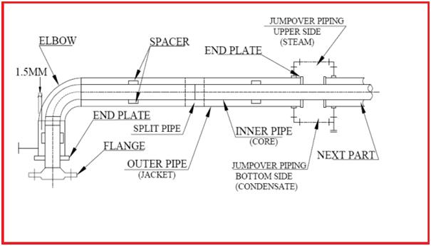
Jacketed piping requires special stress analysis. Jacketed piping is commonly used to convey very viscous process fluids in an inner pipe, heated by steam/hot water/hot oil or other heating media between the jacket and core pipe. Fig 1 shows the normal components of a jacketed piping system. General Definitions of Jacketed Piping Components for stress analysis are mentioned below:
Fig. 1: Components of a Jacketed Piping System
Partition Plate/End Plate:
A partition plate or end plate shall be placed where the flow of steam or heating medium is interrupted for fully jacketed system or at the end of the partially jacketed system. The detailed dimensions and designs shall be as a design guide prepared by the layout team for jacketed piping.
End Closure:
End closure shall be used to terminate jacket piping. There are two types of end closure: Cap Type and Plate Type.
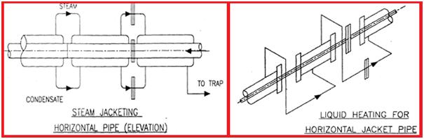
Jump-over:
The length of a single jacket circuit is limited & the supply of heating medium cannot be provided separately for each circuit. Jump-overs (Fig. 2) are used to connect two different jacket circuits in series for a continuous supply of heating medium and draining system. Details of Jump-over sizes and design shall be as per the guide prepared by the layout team for jacketed piping.
Fig. 2: Figure showing typical jump overs in Jacketed Piping System
Jacket Medium:
The heating medium can be gas or liquid.
Reinforcing Ring Plate:
In case the jacket pipe is to be terminated on the core pipe having a thickness of SCH 10S and below, the core pipe shall be suitably reinforced with a reinforcement ring at the weld joint.
Supporting Concept for Jacketed Piping Systems
All supports shall be provided on the jacket pipe.
CAESAR II Modelling of Jacketed Piping
Modeling the Core Pipe:
The core pipe of a jacketed piping system is modeled in Caesar II as per the below-mentioned steps
Do not give pipe insulation thickness while modeling core pipe.
The temperature should be the temperature of the process line.
Pressure should be the pressure of the process line.
Fluid density should be the fluid density of the process fluid.
No wind/wave or earthquake is to be applied on the core.
All core bends are of large diameter (R = 1.5D). For slurry lines where the radius may be 4D then the same shall be entered (refer to project standard).
In the case of Cross-Arrangement for providing a rodding facility, SIF can be obtained from the vendor and shall be entered in all four points of Cross-Connection.
No supports shall come directly on the core pipe.
The selection of node numbers is the same as normal pipe modeling starting from node 10.
All spiders, which are acting as internal supports, can be modeled as vertical restraints plus lateral restraints (guides) with gaps as mentioned in the jacketed piping specification.
The location of the spider shall be presumed before modeling & provide a free node at that location.
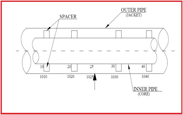
At places where the jacket will be supported, give node numbers of those locations in the core pipe like 5, 15, 115 (Refer to Fig. 3), etc. All other nodes will be multiple of 10.
The starting and finishing node to the rigid node should be defined as restraints, which will help to connect the core pipe and jacket pipe.
All rigid elements shall be modeled as a normal modeling procedure.
Modeling the Jacket Pipe:
The following steps are used to model the jacket pipe:
An easy way is to model the jacket pipe by running through the entire core and then duplicate the core piping using a proper node increment (like 1000).
Change the diameter of the jacket pipe according to the specifications.
Change the wall thickness of the jacket pipe.
All jacketed bends are of short radius i.e. R=1D. For slurry lines, the radius may change. Refer to project standard.
In the case of Cross-Arrangement for providing a rodding facility, SIF can be obtained from the vendor and shall be entered in all four points of Cross-Connection.
Apply insulation thickness and insulation density.
Apply wind/wave/seismic if any.
The temperature should be the temperature of the heating medium.
Pressure should be the pressure of the heating medium.
All supports should be on the jacketed portion only.
If steam is flowing in the jacket pipe then put the density as zero, otherwise, follow the formula provided in the next point.
If both the jacket and the core are fluid-filled, the fluid density of the jacket must be reduced to avoid excess (incorrect) weight. Caesar-II does not do this automatically.
Calculate the actual density as per below calculation:-
Actual jacket fluid density = [(rj2 – Rc2)/ rj2 ] x dj
Where, rj = Inner radius of the jacket; Rc = Outer radius of the core; dj = Density of heating medium
Fig. 3: Figure showing the node numbering
Combining the Core and Jacket Modeling:
The jacket will end with flange joints/ Plate/ Capped End. So at these points, there will be a physical connection between the core and the jacket. So these points need to be connected by an anchor. For example, if there is a flange at node 50 then;
50 ANC CNODE 1050; 60 ANC CNODE 1060
Delete the rigid element 1050-1060 from the jacket portion.
At the spider locations, define Y, and Z restraints (on the core pipe) if the pipe is in the X direction and then connect it by giving CNODE on the jacket.
If the line is partially jacketed then model it the same as the full jacket piping and delete the element from the jacket portion where the line is not jacketed.
Somewhere in the full jacketed system delete the rigid element.
In some systems, the jacket and the core consist of different materials. This condition must be modeled very carefully since the thermal growth in the core will be different from the thermal growth of the jacket.
In general engineering practice, the maximum length of the jacket served by one hot water inlet shall be 20m and one steam inlet shall be 25m.
In the same way, the total length of one circuit shall not exceed 20m in case of continuous jacketing and 25m in case of discontinuous jacketing.
Max length required for a single jacket shall also be dependent on the buckling load (Pcr) check.
Jump-overs shall be designed such that air pockets may be avoided with a heating medium as the liquid.
The flow of the heating medium through the jacket shall be in series to avoid any cold points in the system.
For heating medium, as liquid, the feed and drain nozzle shall be provided at the lowest and highest point of the jacket respectively. For heating medium, as vapor, the feed and drain nozzle shall be provided at the highest and lowest point of the jacket respectively.
As far as possible flange joints on the core pipe shall be avoided. They are to be provided only at equipment nozzles, valves, sp. fittings, instruments, etc. having flanged ends. Also for lines that need to be dismantled during maintenance.
Additional lateral restraints, in the form of spacers, can cause high axial loads which could conceivably initiate distress at the pipe to flange welds.
Spacers should be located to act only as ‘supports’ for the deadweight bending of the core pipe. The indiscriminate location of spacers can produce a “locked-up” condition resulting in high expansion stresses. Check forces on Spiders. The forces shall not be too high that cause bending/ crushing of spiders. Spider is meant just for alignment.
Sometimes break-up flanges may be required after each change in direction. Stress engineer to model the same from initial modeling. And sometimes in a straight run, two/three break-up flanges may come. In that case, the force and moment at anchor points will be too high if the temperature differential between the core and jacket is large.
The weight of flanges and valves used for jacketed piping and flanges will be reduced flanges and valves may be jacket valves. Weight shall be taken from vendor print.
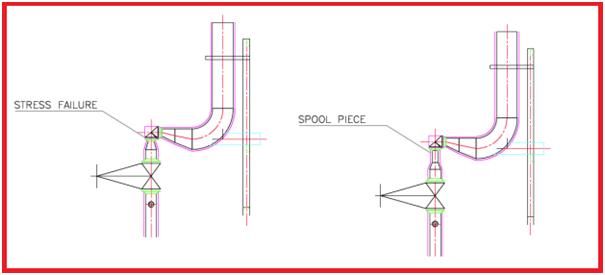
After each jacketed reducer provide at least a 300 mm spool piece (Refer to Fig. 4) before attaching any flange or reducer to reduce chances of thermal failure if required. Inform the layout about this from the initial stage to avoid unnecessary changes later. (For control valve assembly and PSV lines)
Fig. 4: Spool piece in between flange and reducer to avoid stress failure.
Specifying a Jacketed Piping
Jacketed piping is a type of piping used in applications where the process fluid needs to be maintained at a specific temperature. The jacket is typically an outer shell that surrounds the inner piping, which is used to circulate a heating or cooling medium. Here are some general specifications for jacketed piping:
Materials: The materials used for the inner and outer piping and the jacket depend on the process conditions and the fluid being transported. Typically, carbon steel, stainless steel, or other alloys are used.
Pressure Rating: The pressure rating of the jacketed piping should be equal to or greater than the pressure rating of the process piping. This ensures that the system can handle the pressure of the process fluid.
Insulation: The jacketed piping should be insulated to minimize heat transfer between the jacket and the environment. The insulation material should be chosen based on the temperature range and the application.
Welding: Welding of jacketed piping should be done in accordance with the relevant industry standards, such as ASME B31.3 or B31.1. The welds should be tested and verified to ensure the integrity of the system.
Connections: Connections between the jacketed piping and other components, such as pumps or vessels, should be designed to minimize stress and prevent leakage. Flanges, threaded connections, or welded connections can be used depending on the application.
Testing: The jacketed piping system should be tested to ensure that it meets the specifications and is functioning properly. Tests may include hydrostatic testing, pneumatic testing, or other non-destructive testing methods.
Quality Control: The manufacturing and installation of jacketed piping should be done with strict quality control measures to ensure that the final product meets the specifications and is safe for use in the intended application.
It’s important to note that specific jacketed piping specifications may vary depending on the application and industry standards. Therefore, it’s essential to consult with experts in the field to ensure that the design and installation meet the specific needs of the application.
Jacketed Piping Fabrication Procedure
The fabrication procedure for jacketed piping typically involves the following steps:
Material Selection: Select the appropriate materials for the inner and outer piping and the jacket. The materials should be compatible with the process fluid and the heating/cooling medium. The selection should consider factors such as temperature, pressure, corrosion resistance, and cost.
Cutting and Shaping: Cut the inner and outer piping to the required lengths and shapes using cutting tools such as saws or torches. Ensure that the cutting is done accurately to achieve a tight fit between the inner and outer piping.
Welding: Join the inner and outer piping using welding techniques such as TIG, MIG, or stick welding. The welding should be done in accordance with industry standards and the appropriate welding procedure specifications (WPS).
Jacketing: Wrap the outer piping with the jacket material, ensuring that there is sufficient space between the inner and outer piping for the heating/cooling medium to flow. Secure the jacket material to the outer piping using welding or clamping.
Insulation: Apply insulation material around the jacketed piping to minimize heat transfer between the jacket and the environment. The insulation material should be selected based on the temperature range and the application.
Pressure Testing: Test the jacketed piping system to ensure that it can handle the process pressure without leaks or failure. The test should be done in accordance with industry standards and applicable codes.
Quality Control: Perform quality control checks throughout the fabrication process to ensure that the final product meets the required specifications and standards.
It’s essential to follow the appropriate fabrication procedure and industry standards to ensure that the jacketed piping system is safe and efficient. Additionally, it’s important to consult with experts in the field to address any specific concerns or requirements for the application.
CAESAR II vs START-PROF Piping Stress Analysis Software Comparison
In this article, we will compare START-PROF and Caesar II functions. In START-PROF all pipes, fittings, and nodes are objects. Each object has its properties. For example, you can place bend objects into node objects. You can place a pipe or rigid element between two node objects. You can place bend, tee, reducer, valve, and flange objects into node objects.
Material Database
The material database contains the flag “maximum f=1.2” for materials where it can be applied.
Fig. 1: Material Database
FRP/GRP/GRE Material Properties
A3 and System design factors are calculated automatically where needed. al() and hl() already multiplied by temperature factor A1 in the database. All material properties are stored in the material database, and all pipe and fitting properties are stored in the pipe and fitting dialog windows.
No analog in Caesar II. The database contains all data needed for the HDPE piping analysis. Just select the material and then work like it’s steel piping. See Video about the HDPE piping analysis.
Fig. 3: HDPE Piping Material Database
Fig. 4: Plastic Piping System
Pipe Modeling
Different temperatures, pressures, etc. (see “L” button) can be different in different operation modes. Pipe uniform weight can be calculated depending on material density. Weld quality factors W got from the database automatically.
Start to consider high pressure for ASME B31.3-2016 Ch.IX automatically (different wall thickness check, occasion load factor k=1.2, different allowable calculation), not just removing liberal stress.
Additional properties of the pipe looks different depending on the selected code. Here shown B31.1, B31.4, B31.8, ISO 14692, Plastic Piping:
Bends Modeling
START-PROF shows SIF and k-factors for all fittings (bends, tees, reducers, joints) right in the fitting properties dialog box and in the stress table
Elbow Modeling
By default, all bend properties got from the matching pipe. But you can change its material, weight, wall thickness, etc.
ASME B16.9 and all ASME B31 codes don’t regulate the bend, tee, and reducer wall thickness. Only the pipe wall thickness is regulated. So many people think that the elbows and other fittings have the same or almost the same wall thickness as the matching pipe. But in most cases, the real bend, tee, reducer body wall thickness is greater than the matching pipe wall thickness with the same Schedule.
For elbows, the real wall thickness can be 10%-40% greater than the matching pipe. Because bends must have greater wall thickness to hold the same pressure as the connected straight pipe.
Manufacturers usually produce the bends with a greater wall thickness than matching pipe, but we can get real bend wall thickness only after contacting the manufacturer or even measuring it after delivery.
According to the ASME B31 and other ASME B31-based codes bend flexibility factor depends on real bend wall thickness, not on matching pipe wall thickness.
To solve this problem we added a special feature in PASS/START-PROF software that allows calculating the approximate “real” bend wall thickness on the fly according to ASME B31.3 304.2.1 and the same requirements in other ASME B31 and EN 13480 codes. Just push the button “C” near the “Wall Thickness” field and it will be calculated according to the code requirements.
Miter Bends
Non-Standard Bends
For non-standard bends, the user can apply SIFs and k-factors manually.
Other Bends
No analog of such elements in Caesar II
Long radius bend – section manufactured through pipe bending using a large radius, usually R>40DN. Does not have initial forces and stresses. Used in long pipelines
Prestressed long radius bend – elastically bent pipe section with a large radius of R>1000DN (natural curve). Unlike a big radius bend, an elastic bend has initial stress. Used in long pipelines
Miter joint (widely spaced miter bend) – single miter joint that is used for modeling the widely spaced miter bends of a standalone element
Plastic/FRP Bends
Tees
Welding Tee
The START-PROF tee model is complex and contains internal hidden nodes. The tee run is automatically modeled as the pipe with a wall thickness that can be greater than the connected pipe (tn). That’s why START-PROF has “L” and “H” fields. Flexible connections are inserted on the header and branch if needed (if the user selected ASME B31J code or ASME BPV SIII div 1 class 1 NB 3686 method). No side software is needed to use ASME B31J, it’s embedded.
1 – rigid element, 2 – tee header with user-specified wall thickness,
3 – pipe connected to tee header with a different wall thickness
SIF and k-factors are calculated automatically for all standard tees.
A reducer is a node object, not a pipe element. You can delete it and the geometry will not be changed.
Other Elements
Joints
Valves
A valve is a node object. Not pipe. You can delete it and geometry will not be changed. Modeled as a rigid element with specified weight.
Rigid Element
A rigid element is a “special” pipe object
Ballasting Weight
It is a special object used for modeling ballasting on underwater buried pipelines.
Flange Pair
Flange pair modeled as a rigid element. A leakage check can be done.
Restraints
START-PROF has several “standard” supports that are most often used. And “Nonstandard Restraint” for everything else. Also, START-PROF allows specifying allowable loads. If the support load is greater than allowable the table cell will be colored red and warning messages appear in the errors and warnings window.
Sliding Support:
Guide Support:
START-PROF Guide support consists of vertical and horizontal restraints. Allow setting the gap and friction factor. Allows to define allowable loads
Variable Spring Hanger/Support
The hanger table for spring selection is defined in project settings. START-PROF has a variable spring database that contains springs from several manufacturers. The database will be expanded in the future.
START-PROF has two types of springs: Hangers and Supports. Rod lengths can be specified for hangers and friction factors for supports. If the operation load or stiffness will be left blank, the software will select it automatically. During selection, the software suggests when spring should be replaced by constant spring. After replacement, it will be selected automatically. But the designer should make a decision because constant springs are more expensive.
Constant Spring Hanger/Support
START-PROF has a constant spring database and allows to the selection of correct springs automatically. If vertical force is left blank, then it will be selected
Anchor
Hinged Anchor
Hinged Anchor is used to cut the model into separate parts and for some other purposes. Allows to define allowable loads
Rigid Hanger/Stand
Non-Standard Restraint
Non-standard restraint allows you to create any type of restraint
Loads
Node Forces/Moments
START-PROF has a slightly different ideology based on Operation Mode Editor ideology.
Additional weight loads are used for all operation modes cases including seismic.
Non-weight loads are used for all operation modes excluding seismic.
Additional force-based loads are used only in specified load cases, that is usually occasional (relief valve, water hammer, slug flow, etc.).
Uniform Loads
Uniform loads have the same ideology as node loads, see above. Loads in G’s are automatically calculated in START-PROF by a static seismic load generator.
Displacements
In START-PROF no need to create CNODE and connect the node with displacements. Just add the anchor and add the “deformation” into it.
Expansion Joints:
Complex expansion joint models can be created in START-PROF, but it is not needed. START-PROF has standard expansion joint models. Allowable axial, rotation and lateral deformation are checked by the software automatically. The expansion joint report is shown below:
Axial Bellows:
START-PROF has expansion joint database
Axial Slip Joint:
Axial One-time Compensator
This type of expansion joint is widely used in buried district heating networks to perform the cold spring effects.
Gimbal:
Lateral:
Non-Standard:
Wind, Show, Ice, Seismic, Wave Loads:
Wind, Snow, and Ice Loads:
Wind, Snow, and Ice loads can be generated automatically. No Snow and Ice loads generator in Caesar II
Seismic Loads:
Wave Loads:
There are no wave loads in START-PROF yet.
Load Case Editor = Operation Mode Editor:
START-PROF has a high-level Operation Mode Editor, based on templates. That allows doing the same things as Load Case Editor but in a more fast and easy to understand manner.
Other Features:
START-PROF always considers Bourdon Effect (Translation & Rotation). The occasional load factor is taken according to the selected code and chosen in the operation mode editor. The SIF multiplier for sustained stress is always according to the selected code.
See ASME B31.3 302.3.5 equation (1с). If selected, then the maximum value of stress range factor f can be 1.2 for materials with the enabled option “Maximum f=1.2” in the material database, otherwise, the maximum value always f=1.0.
ASME B31J:
To use more accurate SIF and k-factors just turn on this switch (see below). All calculations and model modifications will be done automatically on-the-fly. No need to use any additional software (B31J Essentials, FEATools).
Units Convention:
Units can be converted at any time on-the-fly. Before analysis, and after analysis. No need to convert the whole model.
Underground (Buried) Piping Analysis:
See Video about buried piping analysis with START-PROF.
There’s no underground pipe modeler in START-PROF. The Soil springs are added automatically each time you run an analysis. You can change the model and run analysis immediately, no need to open a backup copy of the model without soil springs and run an underground pipe modeler again. START-PROF is very fast and easy.
Creep in High-Temperature Piping:
Creep Effect (stress relaxation and self-cold-springing effect) is considered for high-temperature piping in START-PROF. Not just for operating mode, but also for cold mode. The cold mode is the most dangerous for high-temperature piping due to the self-cold springing effect.
Wall Thickness Check:
START-PROF has a special module START-ELEMENTS that allows checking of wall thickness or allowable pressure for pipes, bends, tees, reducers, caps, and flanges. Also before piping analysis START-PROF checks the wall thickness of all pipes and fittings to satisfy pressure requirements for all operating modes.
Pipe Stability (Buckling) Analysis:
START-PROF has several functions to analyze different types of buckling: Upheaval Buckling of Buried Pipeline, Upheaval Buckling of Buried Long-radius Bend, Lateral Buckling of Above-ground Pipe, Vacuum Piping Local Wall Buckling due to external pressure and due to external pressure, axial force and moment
Convergence Problems:
START-PROF has no problems with Iterative convergence. There are no settings that the user must change to achieve convergence. Everything is done automatically.
User Interface Functions:
You can change the properties of one object or group of objects very easily. You can select a part of piping and copy & paste, mirror, rotate, split it. Insert node on the pipe or bend, Move along the pipe or bend node, delete node(just select node, and click DEL button).
You can easily change the properties of multiple objects (bends, tees, pipes, etc.) using the properties float window. START-PROF has all the needed functions to work with independent piping segments.
Analysis result reports are smart and interactive: Code Stress Report, Spring Selection Report, Expansion Joint Report, Flange Leakage Report, Insulation Stress Report, Internal Forces, Support Loads Report, Local Wall Buckling Report, and Node Displacements Report. All reports can be exported into Excel, Word, txt, and HTML.
START-PROF has a smart errors and warnings window that all engineering warnings: Pressure failure, buckling failure, support lift off, Spring hanger variable range >25%, spring hanger load greater than allowable in all operating modes, sustained or fatigue stress failure, etc. Not just only stress failure.
Graphic deformation shows hot/cold and install position, deformation position is simple and easy to understand by end users.
Project Tree:
In the project tree, you can see the temperatures, pressures, etc, color diagram, select the needed group of an object and change its properties, delete, copy, etc. Also in START-PROF, you can see all other object properties like bends, tees, reducers, etc.
PDMS Interface:
START-PROF has free PDMS and E3D interface: See Video
Sun Shades for the Oil and Gas Industry and their Design
In the oil and gas industry, a sunshade is a device that is used to protect workers, equipment, and instrumentation from direct sunlight and heat. Sunshades are commonly used in areas where there is a lot of direct sunlight, such as drilling sites, refineries, and production facilities.
Sunshades can come in a variety of shapes and sizes, but they are typically designed to provide a shaded area that can be used for a variety of purposes. For example, sunshades can be used to provide shade for workers who are performing maintenance on equipment or to protect sensitive instrumentation from the heat and light of the sun.
In addition to providing shade, sunshades can also help to reduce the temperature in an area, which can make it more comfortable for workers and reduce the risk of heat-related illnesses. Sunshades can be made from a variety of materials, including metal, fabric, and plastic, and can be designed to be portable or permanent depending on the specific needs of the site.
Applications of Sunshades
Sunshades have several important applications in the oil and gas industry, including:
Protecting workers: Sunshades provide a shaded area where workers can take breaks, perform maintenance tasks, or work on equipment without being exposed to direct sunlight and the associated heat and UV radiation. This can help to reduce the risk of heat exhaustion, sunburn, and other heat-related illnesses.
Protecting equipment: Sunshades can be used to protect sensitive equipment, such as instrumentation and electronics, from direct sunlight and heat. This can help to prolong the life of the equipment and reduce the risk of equipment failure due to overheating.
Improving safety: Sunshades can help to improve safety on oil and gas sites by reducing the risk of accidents and injuries caused by glare and reflections from the sun. Sunshades can also help to improve visibility by reducing the amount of sunlight that enters work areas.
Enhancing productivity: By providing a shaded area where workers can take breaks or perform tasks, sunshades can help to improve productivity on oil and gas sites. Workers are less likely to become fatigued or suffer from heat-related illnesses, which can help to increase their efficiency and effectiveness.
Reducing energy consumption: Sunshades can help to reduce energy consumption on oil and gas sites by reducing the amount of direct sunlight that enters buildings and work areas. This can help to reduce the need for air conditioning and other cooling systems, which can in turn reduce energy costs and greenhouse gas emissions.
Requirements of Sun Shade
Any building structure used by the industry to store raw materials or for manufacturing products of the industry is known as an industrial building.
Industrial buildings can be categorized as normal-type industrial buildings & special-type industrial buildings.
Normal-type industrial buildings are shed-type buildings with simple roof structures on open frames.
These buildings are used for workshops, warehouses, etc.
Sunshades in the oil & gas industries are to be provided to cover the main equipment like compressors, turbines, and pumps, etc.
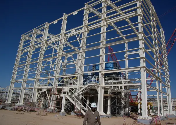
These shades require large and clear areas unobstructed by the columns.
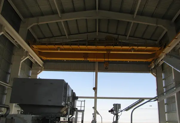
The sunshades are constructed with adequate headroom for the use of an overhead traveling crane.
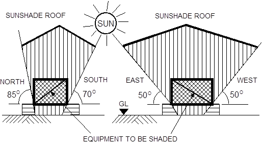
As sun shades are specifically designed to protect equipment from solar radiation, their sizes are directly related to the angle of the sun during the most intense period of this solar radiation.
Accordingly, the equipment that needs to be shaded shall be within the boundaries and angles shown in Fig. 1 below.
Sunshade analysis can be done manually as well as with the help of software also.
For manual analysis, anyone portal to be considered and loads will apply on 2d frames and different forces in columns, beams, and portal or truss members can be found out.
In the recent period, different software is available for the analysis & design of 3d geometry
Sunshade geometry can be easily modeled in STAAD
After geometry finalization, different loads & load combinations are to be applied to the sunshade model in STAAD itself.
After completing the load combination, run the analysis package in STAAD, and all forces and reactions will be generated.
Design of Sunshade
Different codes for designing structural steel shade