Recent Posts

Internal Pipe Coating | FBE Coating | Glass-Flake Coating | PE & ROTO Lining

Internal pipe coating is a crucial process in the field of pipeline infrastructure, particularly in industries like oil and gas, water supply, and chemicals. It involves the application of protective coatings to the inner surface of pipes to prevent corrosion, improve flow efficiency, and enhance the longevity and reliability of the pipeline system. In this comprehensive guide, we will delve into every aspect of internal pipe coating, from its purpose and benefits to the various methods and materials used in the process.

What is Internal Pipe Coating?

Pipe internal coating refers to the process of applying a protective coating on the inner surface of pipes, typically used in oil and gas pipelines or water distribution systems. Internal pipe coating, also known as pipe lining, or pipeline coating, is a process used to apply protective coatings to the inner surface of pipes. The primary purpose of this coating is to prevent corrosion, reduce friction, and extend the service life of pipelines in various industries. The internal pipe coating also reduces the need for frequent maintenance and repairs.

Various types of coatings are available, including epoxy, polyurethane, and ceramic coatings. The selection of the coating type depends on the material being transported, the operating conditions of the pipeline, and the environmental factors in the area.

The process of applying pipe internal coating typically involves surface preparation, cleaning, and the application of the coating material using specialized equipment. The coating is usually applied as a liquid or powder and then cured through heat or chemical reaction, creating a durable protective layer on the inner surface of the pipe.

The purpose of this article is to provide brief information about different types of pipe internal coatings/linings, their uses, advantages, and limitations.

Purpose of Internal Pipe Coating

Pipe internal coating offers several advantages, including:

  • Corrosion protection: The primary advantage of pipe internal coating is the protection of the parent pipe from corrosion. The coating prevents the metal surface of the pipe from coming into contact with the fluid or gas transported through the pipeline, thus reducing the risk of corrosion and extending the life of the pipeline.
  • Improved flow efficiency: The coating provides a smooth, frictionless surface that can improve the flow efficiency of the pipeline. This can result in reduced pressure drop, decreased energy consumption, and increased flow capacity.
  • Reduced maintenance costs: Coating the inner surface of pipes can help to reduce maintenance costs associated with pipeline corrosion and degradation. By preventing corrosion, the coating can help to extend the life of the pipeline and reduce the need for frequent maintenance and repairs.
  • Improved product quality: In pipelines used for transporting liquids, coating the inner surface can prevent contamination and maintain the quality of the product being transported.
  • Environmental protection: Pipe internal coating can prevent leaks and spills caused by pipeline degradation, reducing the risk of environmental contamination.
  • Contaminant Control: In some applications, internal pipe coatings can be used to prevent the contamination of fluids by foreign materials, such as particles or impurities present in the pipeline.
  • Minimizing deposit formation

Overall, pipe internal coating can help to improve pipeline performance, reduce maintenance costs, and extend the life of the pipeline, making it a valuable investment for pipeline owners and operators.

Types of Pipe Internal Coatings / Lining

There are several types of industrial pipe internal coatings, including:

  • Epoxy coatings: Epoxy coatings are the most commonly used type of coating for industrial pipelines. They provide excellent corrosion protection and are resistant to chemicals and abrasion.
  • Polyurethane coatings: Polyurethane coatings offer similar corrosion protection to epoxy coatings but are more resistant to impact and abrasion. They are often used in pipelines that are subject to heavy wear and tear.
  • Ceramic coatings: Ceramic coatings are highly resistant to corrosion, erosion, and abrasion. They are typically used in pipelines that transport highly abrasive or corrosive materials.
  • Polymer coatings: Polymer coatings are a type of liquid-applied coating that provides excellent corrosion protection and can be used on a wide range of pipeline materials, including steel, concrete, and plastic.
  • Polyethylene coatings: Polyethylene coatings are a type of thermoplastic coating that is used to protect pipelines from corrosion and abrasion. They are often used in pipelines that transport water and other fluids.
  • FBE (Fusion-Bonded Epoxy): FBE coatings are applied using a fusion process and provide excellent adhesion and corrosion protection. They are widely used in the oil and gas industry.
  • Cement Mortar: Cement mortar linings are often used in water and sewage pipelines. They provide a dense, protective layer that resists chemical and biological attacks.
  • Internal Plastic Coatings: These coatings are typically made from high-density polyethylene (HDPE) or polypropylene and are used for corrosion protection and abrasion resistance in industrial applications.

The selection of the type of internal pipe coating depends on several factors, including the type of material being transported, the operating conditions of the pipeline, and the environmental factors in the area.

Internal Pipe Coating Methods

There are several methods for applying internal pipe coatings, each with its advantages and limitations:

  • Spray Application: This method involves spraying the coating material onto the interior surface of the pipe. It is suitable for a wide range of coating materials and pipe sizes.
  • Brush or Roller Application: Manual application with brushes or rollers is used for small-diameter pipes or when access is limited. It requires more labor but can achieve good results.
  • Flow Coating: In this method, the coating material is poured into the pipe, and the pipe is rotated to ensure uniform coverage. It is suitable for large-diameter pipes.
  • Centrifugal Spinning: This method is used for applying cement mortar linings. The pipe is rotated, and a mixture of cement mortar is poured in, allowing centrifugal force to evenly distribute the lining.
  • Electrostatic Spray: Electrostatic spray guns charge the coating material, ensuring even distribution and adhesion to the pipe’s surface. This method is used for specific coatings and industries.
  • Internal Pipe Blasting: Before coating, the interior surface of the pipe may be abrasive blasted to remove rust, scale, and contaminants, creating a clean, rough surface for better adhesion.

The choice of coating method depends on factors like pipe size, material type, and project requirements.

Application Process

The application process for internal pipe coating involves several key steps:

  • Mixing: The coating material is prepared according to the manufacturer’s instructions, ensuring proper consistency and quality.
  • Application: The chosen method (e.g., spraying, flow coating, centrifugal spinning) is used to apply the coating to the interior surface of the pipe. Multiple coats may be applied, depending on the project’s requirements.
  • Curing: The coating is allowed to cure or harden, typically under controlled temperature and humidity conditions. Curing time and conditions vary depending on the coating material.
  • Inspection: After curing, the coated pipe is inspected to ensure uniform coverage, adhesion, and quality.
  • Testing: Various tests, such as holiday detection (to identify pinholes or voids) and adhesion tests, may be performed to verify the coating’s integrity.

Applications of Internal Pipe Coating

Internal pipe coating is used in various industries and applications, including:

  • Oil and Gas: Internal coating is essential in the oil and gas industry to protect pipelines from corrosion caused by transported fluids and harsh environments.
  • Water and Wastewater: Coatings are used in water distribution and sewage pipelines to prevent corrosion and maintain water quality.
  • Chemical Processing: Chemical pipelines often require specialized coatings to resist the corrosive effects of the chemicals they transport.
  • Food and Beverage: In food processing, coatings help maintain the purity of fluids and prevent contamination.
  • Pharmaceuticals: Pharmaceutical pipelines must meet stringent quality standards, and coatings help ensure product integrity.
  • Mining and Slurry Transport: Coatings are used to protect pipes in mining operations where abrasive materials are transported.
  • Power Generation: In power plants, coatings help protect pipes that transport water and steam.
  • Marine and Offshore: Internal coatings are used in maritime applications to prevent corrosion in pipelines exposed to seawater.

Examples of Internal Pipe Coatings

In the next section, we will discuss about three most common pipe internal coating and linings used in the oil and gas industries. Common pipe internal coating and linings used for industrial piping systems are

FBE (Fusion Bonded Epoxy) Coating

Image showing FBE Coating
Fig. 1: Image showing FBE Coating

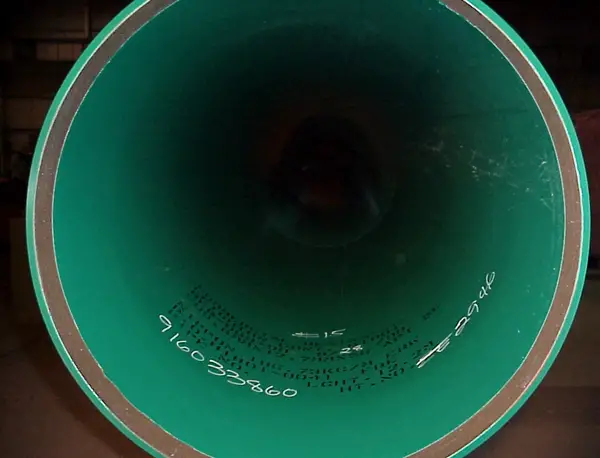
FBE or Fusion Bonded Epoxy is a high-performance anti-corrosion powder coating for moderate operating temperatures, generally suitable up to 80 °C. For higher temperature applications, special FBE grades such as TK-216 (up to 95 °C) & TK-236 (up to 120 °C) can be qualified subject to the Client’s approval.

FBE Coating Application Procedure

The following steps are generally followed for FBE coating application inside piping and pipeline systems:

  • Visual inspection before blast cleaning to check the presence of oil, grease, etc.
  • The steel surface is thoroughly cleaned by blast cleaning which removes rust, scale, etc, and produces a rough surface finish. The roughness value required is 50 – 100 microns.
  • Heating: Induction heating or oven heating, usually in the range of 180 to 250 °C

The Application and Curing Stage

Internal surfaces of pipes are coated using a spray gun, which travels from one end to the other end of the heated pipe at a uniform speed, while the pipe is being rotated in its longitudinal axis. After coming in contact with the hot surface, the powder melts and transforms into a liquid form. This liquid FBE film flows onto the steel surface and soon becomes a solid coating by chemical cross-linking, assisted by heat. This process is known as “Fusion Bonding”.

Standard FBE coating thickness ranges between 250 to 500 microns (0.25 to 0.5mm).

After field welding of the pipe ends, FBE can be applied to the weld area as well.

FBE Coating Advantages

The main advantages that FBE coating provides are

  • Suitable for higher temperatures compared to PE/ROTO lining
  • Excellent adhesion to steel provides superior long-term corrosion resistance
  • It can be applied to various pipe diameters from 2” to over 48”.
  • It can be applied to a wide range of thicknesses.
  • Good chemical resistance under most soil conditions.
  • Good abrasion and high-impact resistance

Limitations of FBE Coating

However, there are some limitations of FBE coating as listed below:

  • The maximum life of the FBE-coated pipe is 12 years, and if the plant design life is 25 years, one piping replacement is required.
  • Can be applied only in the shop
  • Applicators are not readily available
  • Complex design

Internal Glass Flake Coating (Chemflake, Belzona etc)

internal glass flake coating
Fig. 2: Image showing internal glass flake coating

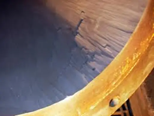
Chemflake/Belzona coatings are glass flake epoxy coatings as per PCS – 8 of SP-1246, normally suitable for up to 93°C operating temperature (Belzona can be used up to 120°C by using specific Belzona grades).

Suitable for higher pipe sizes & where Roto lining can not be carried out because of the weight limitation of the pipe spool.

Generally carried out inside a flanged pipe spool, for joining non-flanged pipe spools Thru-kote sleeves are used.

All flanges of Chemflake & Belzona coated piping shall be provided with a weld overlay of suitable material prior to dispatch for internal coating.

Internal Glass Flake Coating Application stages

  • Cleaning – blast cleaning. The roughness value required is 75 – 130 microns.
  • Spray – Normal airless spray or two-comp. airless spray equipment.
  • Brush – Recommended for stripe coating and small areas. Care must be taken to achieve the specified dry film thickness.
  • Curing – 1 coat requires around 24 hr to get a total dry film.

DFT: 2 x 750 microns (for Chemflake)            1 coat of 1000 microns (for Belzona)

Advantages of Glassflake Coating

The main advantages of glass flake coatings are

  • Good chemical resistance,
  • Good solvent resistance,
  • Good adhesion,
  • Low permeability,
  • Good weather properties,
  • Excellent gloss retention.

Limitations of Glassflake Coatings

Glassflake coating has the following limitations

  • Temperatures & pressure-dependent – suitable only for up to 10 bar pressure & for non-flowing or less velocity fluids.
  • Not suitable for abrasive fluids/slurries
  • May cause skin irritation,
  • Requires recoating intervals
  • Chalking (for epoxy)-Time-Consuming
  • Very costly
  • Used only for less number of spools, not for the entire project scope
  • Design life is only 3 – 4 years

PE & ROTO Lining

PE & Roto Lining
Fig. 3: Image showing an example of PE & Roto Lining

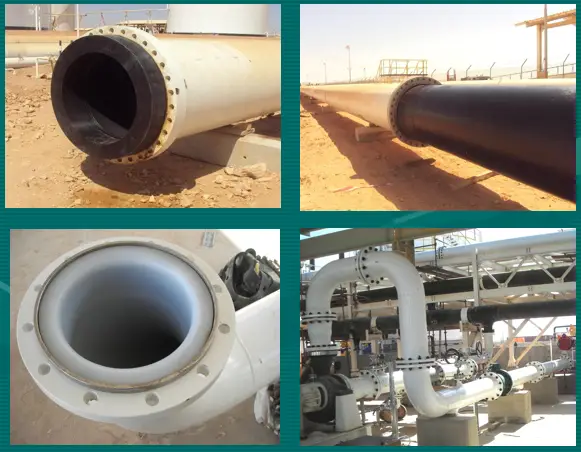
For further design details about PE/Roto lined piping please click here

How does Pipe Internal Coating Work?

Pipe internal coatings work by creating a barrier between the metal surface of the pipe and the fluid or gas being transported through the pipeline. The coating material is applied to the inner surface of the pipe, forming a protective layer that prevents the metal from coming into contact with the fluid or gas.

The coating material can be applied using various methods, including spraying, brushing, or rolling. The coating material is usually a liquid or powder that is cured to form a durable, solid layer on the pipe’s inner surface.

Once the coating has been applied, it forms a protective barrier that helps to prevent corrosion, erosion, and other forms of degradation. The coating can also improve the flow efficiency of the pipeline by providing a smooth, frictionless surface.

The effectiveness of pipe internal coatings depends on several factors, including the type of coating used, the quality of application, and the operating conditions of the pipeline. Proper surface preparation and application techniques are critical to ensuring the coating adheres to the surface of the pipe and provides effective protection against corrosion and degradation.

Internal Pipe Coating Companies

There are several companies that specialize in internal pipe coating, including:

  • Shawcor: Shawcor is a global company that provides a wide range of internal pipe coating solutions for various industries, including oil and gas, water, and mining.
  • Axalta: Axalta is a leading supplier of industrial coatings, including internal pipe coatings. They offer a range of coatings that are designed to provide corrosion protection and improve pipeline performance.
  • PPG Industries: PPG Industries is a global supplier of paints, coatings, and specialty materials. They offer a range of internal pipe coatings that provide corrosion protection and improve the flow efficiency of pipelines.
  • Sherwin-Williams: Sherwin-Williams is a leading supplier of protective coatings, including internal pipe coatings. They offer a range of coatings that are designed to provide corrosion protection and improve the durability of pipelines.
  • AkzoNobel: AkzoNobel is a global supplier of coatings and specialty chemicals. They offer a range of internal pipe coatings that provide excellent corrosion protection and improve the performance of pipelines.

These are just a few examples of companies that provide internal pipe coating solutions. There are many other companies that specialize in this field, and the selection of a specific company or solution will depend on several factors, including the type of pipeline and the specific needs of the project.

Repairing Internal Pipe Coating

The repair of internal pipe coating typically involves the following steps:

  • Inspection: The first step is to inspect the coating to determine the extent and location of any damage. This may involve using non-destructive testing techniques to evaluate the condition of the coating.
  • Surface preparation: Once the damaged areas have been identified, the surface of the pipe must be prepared for repair. This may involve cleaning, sanding, or grinding the damaged area to remove any loose or damaged coating.
  • Patching: The damaged area is then patched with suitable repair material. This may involve using a filler material, such as an epoxy-based repair compound, to fill in the damaged area.
  • Coating application: Once the patching material has cured, a new coating is applied to the repaired area to restore the protective barrier.

The specific repair method will depend on the type and extent of damage to the coating. In some cases, minor damage can be repaired using a patching material and touch-up coating. In more severe cases, the damaged section of the pipeline may need to be cut out and replaced with a new section, followed by the application of a new coating.

It is important to follow proper repair procedures to ensure that the coating provides effective protection against corrosion and degradation. In some cases, it may be necessary to consult with a specialist or the coating manufacturer to ensure that the repair is performed correctly.

PE and RotoLining Design Considerations are covered in a separate detailed article that can be accessed by clicking here.

Changes in ASME B31.3-2018 with respect to the ASME B31.3-2016 edition

What is ASME B31.3?

ASME B31.3 is part three of the overarching ASME B31 Code for Pressure Piping and it applies to pipe systems that transport chemicals, petroleum products, fluidized solids, refrigerants, cryogenic fluids, and gas, steam, air, and water. ASME B31.3, also an American National Standard prescribes guidelines for materials and components, design, fabrication, assembly, erection, examination, allowable stress, acceptance criteria, and testing of process piping to aid numerous groups which include the owner of the piping installation, as well as the designer, owner’s inspector, and manufacturer, fabricator, and erector.

Major Changes in ASME B31.3-2018

Most of you must be aware that ASME B31.3-2018 which revises the 2016 edition of the same standard for process piping has been published in the month of August 2019 with the date of issuance as 30th August 2019. This code will be universally applicable after six months from the date of issuance i.e from March 2020 onwards. In addition to the many clarifications, and updated references to codes and standards, there are few substantive changes made to the latest edition of this standard, a few of which are mentioned below:

Changes with Respect to the Scope of B31.3

1. The scope of the ASME B31.3 has been revised in the 2018 edition as compared to the earlier 2016 edition. Now the latest code specifically mentions that the piping for onshore and offshore petroleum and natural gas production facilities, ore processing, food and beverage processing facilities, etc are included in the scope.

Specific Permission of Owner

2. Added specific permission for the owner to designate a representative to carry out selected responsibilities required by this Code, and noted that the owner retains ultimate responsibility for the actions of the representatives.

New Appendix W

3. New appendix W related to “High-Cycle Fatigue Assessment of Piping Systems” is added in the recent edition of the Code. The method is intended to be used when the number of significant stress cycles exceeds 100,000.

A significant stress cycle is defined as a cycle with computed stress ranges greater than 20.7 MPa (3.0 Ksi) for ferritic and austenitic steels. For other materials. or corrosive environments, all cycles shall be considered significant unless otherwise documented in the engineering design. The existing rules provide an acceptable method of evaluating piping systems for fatigue when the number of significant stress cycles is less than or equal to 100,000. The piping cyclic loadings may be due to thermal expansion, anchor motion, vibration, inertial loads, wave motion, or other sources.

Additional Piping Vibration Sources

4. External vortex shedding (e.g., wind), Acoustically Induced Vibration (AIV), etc are added additionally as piping vibration sources against which the piping system must be designed and supported compared to the earlier edition of B31.3.

Basis Of Design Stress

5. Basis of Design stress values in clause 302.3.2 is revised from 2016 values.

Weld Joint Stress Reduction Factor

6. Weld joint strength reduction factor, W, was included as an allowance for pressure and temperature variations. A new row for Carbon Steel was added in Table 302.3.5, “Weld Joint Strength Reduction Factor, W.

Elevated Temperature Fluid Service

7. For Elevated Temperature Fluid Service the allowable stress for occasional loads of short duration, e.g., surge, extreme wind, or earthquake, has been modified with respect to B31.3-2016, and now it may be taken as the lowest of a, b or c:

  1. the weld strength reduction factor times 90% of the yield strength at the metal temperature for the occasional condition being considered
  2. four times the basic allowable stress provided in Appendix A of the code
  3. for occasional loads that exceed 10 h over the life of the piping system, the stress resulting in a 20% creep usage factor in accordance with Appendix V of the code.

Flange Design

8. The new edition permits to design of flanges following ASME BPVC, Section VIII, Division 2, 4.16 (Design Rules for Flanged Joints) or in accordance with ASME BPVC, Section VIII, Division 1, Mandatory Appendix 2 (Rules for Bolted Flange Connections with Ring Type Gaskets) using the allowable stresses and temperature limits of this Code. For flange design, the reference of code ASME BPVC, Section VIII, Division 2, 4.16 as an acceptable way to design flanges for B31.3 applications is newly added. The Division 2 procedure considers pressure, gasket seating, externally applied axial forces, and net-section bending moments.

Stress Intensification

9. Added specific references to ASME B31J-2017 as a resource for stress intensification and flexibility factors as an alternative to Appendix D.

Heat Treatment for Structural Elements

10. Added explicit language requiring heat treatment for structural attachments welded directly to pressure-containing materials when the piping is required to be heat treated.

11. Added a definition for readily accessible: those surfaces that can be examined from not more than 600 mm (24 in.) and at an angle not less than 30 degrees to the surface to be examined. Increased visual examination required for normal fluid service welds from 5% random to 100%.

Fatigue Analysis for High-Pressure Fluid Service

12. A fatigue analysis is required for all piping systems in Chapter IX High-Pressure Fluid Service. In previous editions, this analysis was permitted to be performed in accordance with the BPV Code, Section VIII, Division 2, or Division 3. Division 2’s fatigue analysis involves using a standard S/N curve to determine the design fatigue life. Division 3 also allows an S/N curve approach, but only if it can be shown that the piping component will fail in a leak-before-burst mode. Otherwise, a more rigorous fracture mechanics evaluation is required. The Division 3 S/N analysis contains several requirements that are not included in Division 2, such as surface finish and means stress corrections. Because the Division 2 approach is less precise than the Division 3 approach, wherever possible, Division 2 was eliminated as an option for the required Chapter IX fatigue analysis. Text on fatigue analysis for unlisted high-pressure piping components was added.

13. Rules for the use of piping components not listed in Table 326.1, “Component Standards,” were altered.

14. The scope of Chapter IX, “High-Pressure Piping,” was revised in its entirety.

15. Table C-6M, “Moduli of Elasticity for Metals (SI Units),” was added.

16. Examples of rounding for piping that has been placed in service were added as new section F300.1.4.

17. General statements were added in Appendix F, “Guidance and Precautionary Considerations.”

18. Appendix Z, “Preparation of Technical Inquiries,” was revised in its entirety.

Users should note that only a portion of the changes to ASME B31.3-2018 is included in the above list. Readers are requested to highlight other major changes in the comments section.

Learn the ASME B31.3 code changes in different years:

What’s new in ASME B31.3-2020? ASME B31.3 2020 vs 2018
Changes in the 2018 Edition of ASME B31.3 2018 with respect to the 2016 edition.
14 major changes in ASME B 31.3-2016 with respect to its earlier edition (ASME B31.3-2014)
Substantive Changes to 2014 Edition of ASME B 31.3
Major Stress-related differences in Between 2012 edition and 2010 edition of ASME B31.3.

DeSalting and Dehydration of Crude Oil

Desalting and Dehydration processes are crucial in the oil industry to prepare crude oil for refining and ensure the quality and safety of the final products. This comprehensive guide will cover everything you need to know about crude oil desalting and dehydration, including the processes involved, equipment used, key parameters, and the significance of these processes in the oil industry.

What is Crude Oil Desalting and Dehydration?

Desalting of Crude oil means the removal of the dissolved salt in the crude oil and increasing the grade of the crude oil. Crude oil dehydration is the process of removing the water present in crude oil to meet the purchaser’s limit. Since salt is dissolved in the water, the dissolved salt is also removed in the process.

Crude oil desalting is the initial step in the refining process, where impurities such as salts and water are removed from the crude oil. The desalting process is critical because failure to remove these impurities can lead to corrosion and fouling of downstream equipment in the refining process, which can be costly and result in suboptimal product quality.

Crude oil dehydration is another critical process in the oil industry, which involves the removal of water from crude oil. Water content in crude oil can lead to several issues, including corrosion, emulsion formation, and reduced refining efficiency.

Reason for Desalting and Dehydration of Crude Oil

Desalting and dehydration are important processes in crude oil refining that help to remove impurities and contaminants from crude oil. Here are some reasons why these processes are important:

  • Protecting downstream equipment: Impurities and contaminants in crude oil can damage downstream equipment such as pumps, valves, and pipelines. Desalting and dehydration help to remove these impurities and contaminants, protecting downstream equipment and ensuring the safe and efficient operation of the refining process.
  • Improving product quality: Impurities and contaminants in crude oil can also affect the quality of the final refined products such as gasoline, diesel, and jet fuel. Desalting and dehydration help to remove these impurities, improving the quality and purity of the final refined products.
  • Reducing corrosion: Impurities and contaminants in crude oil can cause corrosion in pipelines and equipment. Desalting and dehydration help to remove these impurities, reducing the risk of corrosion and extending the lifespan of the equipment.
  • Meeting product specifications: Refined products must meet specific product specifications and quality standards to ensure they are safe and effective for use. Desalting and dehydration help to remove impurities and contaminants that can cause refined products to fall outside of these specifications.
  • Improving safety: Desalting and dehydration can also help to improve safety in the refining process by reducing the risk of equipment failure and leaks caused by impurities and contaminants.
  • Minimizing Fouling: Removing sediments and trace metals reduces the fouling of heat exchangers and refining equipment, leading to more efficient and cost-effective operations.
  • Environmental Compliance: Proper desalting reduces the risk of hazardous conditions, such as hydrate formation, and ensures compliance with environmental regulations by treating waste brine streams.

Overall, desalting and dehydration are important processes in crude oil refining that help to improve the quality, safety, and efficiency of the refining process, and ensure that the final refined products meet product specifications and quality standards.

Why Desalting and Dehydration of Crude Oil?

Crude purchasers place limits on the salt and water contents of the crude they buy, typically:

  • Water 0.2 to 0.5% vol.
  • Salt 70 g/m3

Since salt is dissolved in the water phase, dehydration is also effectively desalting.

During production, the oil and water are mixed and one phase disperses as droplets (dispersed phase) in the other (continuous phase). Maximum mixing occurs at the points of high energy dissipation, e.g. at flow beans, valves, and pumps.

Theories behind Desalting and Dehydration of Crude Oil

Water and oil are separated by virtue of their different densities; gravity is the driving force. For laminar flow conditions, the settling velocity (VT) of an unhindered dispersed phase droplet is given by Stokes Law:

Stokes Law
Fig. 1: Stokes Law

This can be increased by the use of centrifuges, cyclones, or other such devices, although this is unusual in oilfield practice.

Density Difference and Viscosity

Large density differences between oil (ρo) and water (ρw) and low oil viscosities are favorable for easy separation and therefore light crudes separate faster than heavy crudes. An increase in temperature causes a reduction in viscosity, therefore the application of heat can be used to accelerate the separation of heavy crude.

Droplet Size (d)

The settling rate depends on the square of the droplet diameter. Drop-to-drop coalescence increases droplet diameter and for this reason, coalescence is a key factor in successful dehydration. Unfortunately, however, many oilfield dispersions resist coalescence and are known as ‘stable dispersions’ or ‘stable emulsions.

Oil and water mixtures would be highly unstable were it not for naturally occurring surface-active agents (surfactants) and finely divided particles that are absorbed in oil/water interfaces to form rigid films that resist coalescence. In this way, surfactants stabilize fine droplets which then accumulate to form emulsions.

Water in oil emulsions is known as ‘normal’; most oilfield emulsions are in this category. Oil in water emulsions is termed ‘reverse’.

Crude Oil Desalting and Dehydration Procedure

Successful dehydration of crude oil is carried out in three steps

  • Destabilization of the emulsion
  • Coalescence of small drops into large drops
  • Settling out of large drops and separation of the two phases.

Destabilization of the Emulsion

Stable inter-facial films can be broken down by:

  • Chemical demulsifiers
  • Heat treatment
  • pH treatment
  • Increased salinity.

The use of chemical demulsifiers is now the main approach for treating stable oilfield emulsions, often in combination with heat treatment. Demulsifiers are most effective when added prior to the formation of an emulsion.

Dehydration Equipment Selection Guidelines
Fig. 2: Dehydration Equipment Selection Guidelines

Separators in Crude oil Dehydration

Separators are prefabricated pressure vessels, which are suitable for separating oil, water, and gas.

Separators can be designed for ‘free water knock-out’ (FWKO) or ‘dehydration’ service. Both look similar in appearance, but for a given throughout the dimensions of a vessel in dehydration, service is necessarily larger.

A separator designed for free water knockout service will generally only remove free water from the feed stream. The rest of the water will remain dispersed in the crude, typically 5 to 10% vol. for light crudes (ρo < 850 kg/ m3) and 10 to 20% vol. for heavy crude    (ρ o > 900 kg/ m3).

A separator designed for ‘dehydration service’  will dehydrate crudes down to low water content levels, typically 1 to 3% vol. for a liquid-liquid separator and 1 to 5% vol. for a three-phase separator.

Separators for crude dehydration
Fig. 3: Separators for Crude dehydration

Wash Tank/ Concentric Wash Tank for Crude Oil Dehydration

Wash tanks are usually the preferred choice for general-purpose dehydration of light and medium-density crude Oils (ρo < 900 kg/ m3) on land. The water content of the crude at the outlet is typically 1 to 3% vol. Operating temperatures above 85 ºC is not usually because of unacceptable loss of light ends.

A conventional wash tank is shown below:

Crude Oil Dehydration tank
Fig. 4: Crude Oil Dehydration tank

Note that ‘free gas’ is removed upstream of the tank in a gas boot. If deeper dehydration is required then either a separate degassing tank should be installed instead of the gas boot, or consideration should be given to using a concentric wash tank.

Concentric wash tanks are a relatively recent development and are particularly suitable for the dehydration of heavy/viscous crudes.

A typical concentric wash tank is above.

Electrostatic Coalescers for Crude Dehydration

Electrostatic coalescers are pressure vessels fitted with electric grid internals and are suitable for deep dehydration of crude oil. The water content of the crude oil at the outlet is typically in the range of 0.1 to 0.5% vol. The units are relatively compact and therefore suitable for use offshore.

Electrostatic Coalescers
Fig. 5: Electrostatic Coalescers for Crude Dehydration

Crude oil desalting and dehydration are critical processes in the oil industry that prepare crude oil for refining and ensure the quality and safety of the final products. Desalting removes salts, water, sediments, and trace metals from crude oil, while dehydration removes water content. Proper control of key parameters, such as temperature, residence time, and the use of appropriate equipment, is essential for the success of these processes. By implementing effective desalting and dehydration techniques, the oil industry can maximize refining efficiency, reduce equipment corrosion, and produce high-quality products while adhering to environmental regulations.

How to use ASME B31J and FEM for SIF and k-factors for Stress Analysis

How to use ASME B31J SIF and k-factors in PASS/START-PROF

For a long time, there was a need for a standard method to develop stress intensification factors (SIFs or i-factors) for ASME piping components and joints. At the time, the B31 Code books provided SIFs for various standard fittings and joints but did not provide guidance on how to conduct further research on existing SIFs or how to establish SIFs for nonstandard and other standard fittings or joints.

ASME B31J is the outcome of recent research by MDC on current manufacturing practices in the SIF and k-factor test procedures, to provide a consistent and up-to-date table of SIFs and k-factors for metallic piping components.

ASME B31J provides a standard approach for the development of SIFs, k-factors, and sustained stress multipliers for piping components and joints of all types, including standard, nonstandard, and proprietary fittings. However, this code still does not cover fittings that have a D/T ratio greater than 100 for which we have to be dependent on FEA analysis.

So in nutshell, The code ASME B31J-2017 offers us revised, more accurate SIFs and flexibility factors for tees, bends, and reducers. By using these revised SIFs and flexibilities, the pipe stress analysis results become more accurate.

Now the question is How to use it in START-PROF Software?

Very easy. No additional software or model conversion is needed. Just turn on this checkbox:

Click to enlarge

If the “ASME B31J” option is activated then all tees are automatically modeled with simultaneous use of run and branch springs with flexibilities and stress intensification factors calculated according to ASME B31J code requirement:

Tee model

Start-Prof software allows activating “ASME B31J” option for ASME B31.1, B31.3, B31.4, B31.5, B31.8, B31.9 and EN 13480 codes. If some of the k-factor becomes less than 1.0 Start-Prof assumes this spring as rigid:

ASME B31J covers only standard straight tees and D/t less than 100. For nonstandard tees, for example, lateral and tees with D/t greater than 100 Nozzle-FEM software can be used. It can calculate SIF and k-factors which can be used in START-PROF software using a nonstandard tee.

In the next version 4.84, the NOZZLE-FEM software will be embedded into START-PROF and allow to calculate using FEM methods SIF and k-factors for tees. Also, embedded NOZZLE-FEM will allow us to calculate of nozzle flexibility and check nozzle stresses using FEM.

Control Valve Sizing

Control Valve Sizing is a procedure of deciding the appropriate type and size of the control valve to optimally satisfy the requirements of fluid flow management. This article will describe the Control Valve Sizing Procedure with some details of related headings like Valve Flow Terminologies, Control Valve Characteristics, Cavitation, Flashing, etc.

Control Valve Flow Terminologies

The following control valve terminologies are required to define before we proceed with the control valve sizing steps.

  • Pressure Drop: It is the difference between the upstream pressure and downstream pressure of the control valve.
  • Cv (Flow Coefficient): The Cv is the number of U.S. gallons of water flowing during one min. at 60 Deg F through a restriction and the pressure drop through this restriction is 1 psi.
  • Vena contracta: The vena contracta is where the jet of flowing fluid is smallest.
  • Choked or critical flow: The flow is said to be choked when:
    1. Vena contracta is filled with vapor from cavitation or flashing.
    2. Fluid velocity at vena contracta reaches sonic.
  • Vapor pressure: It is the pressure at which the given liquid will vaporize at the given temperature
  • Cf (Critical Flow Factor): The Cf factor is an indication of the valve’s vena contracta pressure relative to the valve’s outlet pressure.

Pressure Recovery Factor in Control Valve Sizing

Pressure Recovery Factor

Control Valve Characteristics for sizing a control valve

Valve characteristics describe the relationship between valve travel and flow rate. Control Valve Characteristics are determined by the Design of the Valve Trim.

Inherent Characteristics

Expresses the relationship between the valve travel and flow rate for a constant pressure drop across the control valve.

  • Quick Opening-On-off control with no throttling.
  • Linear-Flowrate is linear with plug position.
  • Equal Percentage-Equal increment of travel produces an equal % change in the flow.

Relationship between % Flow & % Valve Opening

A typical Characteristic of an Equal percentage Valve

Typical Valve Characteristics

Installed Characteristics

  • Installed Characteristics are what really matter to a process engineer.
  • Expresses the relationship between the valve travel and flow rate for a varying pressure drop across the control valve.
  • Installed characteristics of the Equal percentage valve are nearly linear when pressure drop varies with the flow.

Installed vs Inherent characteristics:

The inherent flow characteristics do not reflect the actual performance of the valve as installed. The ideal condition of constant valve pressure drop (∆P) is unlikely to be true and the ‘operating’ characteristics will have a deviation from the inherent characteristics.

The deviation in the characteristics depends on the pressure drop variation across the control valve, as the control valve operates from minimum flow at its initial travel position to its maximum flow at its fully opened position.

Selection of Valve Characteristics for Control Valve Sizing

The following method should be used for control valve sizing

  • Choose Equal percentage characteristics, if Pvalve < 70% of system Pressure Drop
  • Choose Linear characteristics, if Pvalve > 70% of system Pressure Drop

Data Required for Control Valve Sizing

A combination of theory and empirical data should be used for control valve sizing and selection. Typically, the following data are used for control valve sizing:

  • Operating Flowrates:– Maximum flow; Normal flow; Minimum flow
  • Fluid Properties:-Fluid Phase; Molecular Weight; Vapor Pressure; Ratio of specific heats; Compressibility; Specific gravity; Viscosity
  • Parameters:- Source Pressure; Destination pressure; Design pressure; Operating temperature; Shut off Pressure

Important Parameters for Control Valve Sizing and Selection:

  • Valve size or valve coefficient (Cv)
  • Pressure-Temperature rating
  • Flow medium
  • Service requirements (flow regulation or on-off type)
  • Material of construction
  • Valve Action (Normally Open vs. Normally Closed)
  • Precision control
  • Leakage or Tight shut-off

Control Valve Sizing Procedure

Rangeability:

Rangeability is the ratio of maximum to minimum controllable Cv. It is common practice to select a control valve within the following range:

Maximum flow:

  • Valve opening <= 95 % for Equal Percentage Trim
  • Valve opening <= 90 % for Linear and Quick Opening Trim

Normal flow: Valve opening should be at least 60 %

Minimum flow: Valve opening >= 10 %

Control valves do, what they are told!

The need for the fail-safe position

  • Fail to Open (FO)
  • Fail to Close (FC)
  • Fail Last

FC / FO schematic

Fail Open- Fail Close

Double Acting Actuator

Double Acting Actuator

Control Valve Sizing Calculation

Sizing control valve for Maximum flow-

  • Estimate Maximum required flow
  • Calculate the system pressure drop without the valve
  • Choose a valve that will pass maximum flow when about 90% open.

Size for minimum flow-

  • Follow the same procedure as above and choose a valve that will pass minimum flow when about 10% open

Control Valve Sizing for Normal flow-

  • Follow the same procedure and choose a valve that will pass normal flow when about 60-70% open

Pressure Drop calculation:

Pressure Drop calculation

Cv Calculation for Control Valve Sizing

The flow coefficient or Cv is an important parameter for control valve sizing. This is also known as valve co-efficient. It specifies the number of U.S gallons of water that flows through a restriction in one minute at 60 Deg F keeping the pressure drop through this restriction is 1 psi. The Cv calculation procedure for liquid flow, gaseous/steam flow, and two-phase flow are provided below for reference.

Cv Calculation Liquid flow:

Cv Calculation Liquid flow

Cv Calculation Gas and Steam:

Cv Calculation Gas and Steam

Cv Calculation Two-Phase flow:

Cv Calculation Two Phase flow

Effect of Reducers on Control Valve Sizing

  • Decrease in actual valve capacity
  • Creates additional pressure drop in the system
  • Flow Capacity Correction Factor (R)
Flow Capacity Correction Factor

Thumb Rules for Control Valve Sizing

Some general thumb rules prevalent in industries while sizing control valves are:

  1. Assign the system and size the control valve such that:
    • Pvalve = 25% system pressure drop (including control valve) or Pvalve = 1/3rd system pressure drop (excluding control valve)
  2. The valve is to be sized to operate between 20 to 80% open at the maximum required flow rate.
  3. The minimum opening should not be less than 20% at the minimum flow rate to provide a safety margin

Cavitation and Control Valve Sizing

Cavitation in control valve sizing is a two-stage phenomenon:

  • Formation of vapor bubbles
  • Collapsing of vapor bubbles

Cavitation Phenomena:

Cavitation Phenomena

Negative Effects of Cavitation:

  • Resists the fluid flow
  • Causes severe vibrations
  • Erodes metal surface
  • Generates high noise levels

Cavitation Countermeasures:

  • Select a valve style that has a Cf value greater than required for the application
  • Increase pressure upstream of the control valve by reducing elevation in the piping system
  • Installation of the orifice downstream of the control valve

Flashing

Definition – Pressure at the valve outlet remains below the vapor pressure

Negative effects-Two phase flow in the downstream of control valve; Erosion

Limitations in Control Valve Performance

Noise-

  • 85 dBA for process control and daily service applications
  • 90 dBA for infrequent letdown and recirculation
  • 5 dBA credit may be taken for insulation.

Vibration and Erosion limits

Liquid Service-

  • Trim Exit vel. < 30 m/s for single-phase liquids
  • Trim Exit vel. < 23 m/s for cavitating, flashing erosive services

Gas Service

  • Trim Exit vel. Head > 480 kPa for continuous service
  • Trim Exit vel. Head > 1030 kPa for infrequent service

Positioner

A position controller (servomechanism) that is mechanically connected to a moving part of a final control element or its actuator and that automatically adjusts its output to the actuator to maintain the desired position in proportion to the input signal.

Control Valve Sizing Standard

Widely used control valve sizing standards are

  • ISA75.01.01, Control Valve Sizing Equations
  • IEC 60534-2-1
  • DEP 32.36.01.17-Gen, Control valves – selection, sizing, and specification

Simplified Steps for Control Valve Sizing

The following steps can be followed for simplified Control Valve Sizing:

  • STEP #1: Define a maximum allowable pressure drop for the valve
  • STEP # 2: Calculate the valve coefficient (Cv)
  • STEP # 3: Preliminary valve selection
  • STEP # 4: Check the Cv and stroke percentage at the minimum flow
  • STEP # 5: Check the gain across applicable flow rates: Gain is defined as:
  • Gain = ∆ Flow / ∆ Travel; the gain should never be less than 0.50

Few more Resources for you…

Details about control valves
Ball Valve Design Features: A Literature
A brief article on Valve Inspection & Testing
An article on ROTARY SELECTOR VALVE (RSV) and MULTIPHASE FLOW METER (MPFM)
Selection of Valves: A Few Guidelines
Piping Design and Layout Basics
Piping Materials Basics
Piping Stress Analysis Basics

Underground Piping Stress Analysis Procedure using Caesar II

Several failures in buried piping and pipeline systems over the years forced EPC companies to investigate the stresses the system is experiencing. So, in recent times, stress analysis of underground piping and pipeline systems are made compulsory. In most cases, buried analysis is followed for pipelines as the maximum part of pipeline systems are underground. And the analysis is governed by ASME B31.4 or B31.8 Codes.

In my earlier article on Buried Piping, I explained the theoretical background of stress analysis of underground piping. Click here to visit that article. In this article, I will explain the steps required to follow for modeling and analyzing the pipes in Caesar II.

Inputs Required for Buried Piping Stress Analysis

Like all other piping systems, you need to model the piping in Caesar II initially following the same conventional method. So you need the following inputs:

  • Piping isometrics or GA drawings with dimensions.
  • Pipe parameters like temperature, pressure, material, diameter, thickness, corrosion allowance, fluid density, etc.
  • Additionally, you need the following soil parameters from the civil department (geo-technology department) for the creation of the soil model using the Basic Caesar II soil model.
    • Friction Co-efficient
    • Soil Density
    • Buried depth to the Top of the Pipe and
    • Friction Angle
  • Equipment/Valve GA drawings as per application.

Modeling the piping/pipeline system in Caesar II

Follow the below-mentioned steps:

Model the piping system from isometrics/GA drawings using the pipe parameters.

Normally some parts of the system will be above ground and some parts will be buried. Let’s take an example of a typical system for easy understanding. Refer to Fig 1. The stress system consists of a 24-inch CS pipe connected to a tank. The parts inside the rectangle are above ground and the remaining parts are underground.

Create a distinct node at all the junction points of underground and above-ground piping.

After you complete your model, save it, close it, and then enter the buried model by clicking the Underground Pipe modeler button as shown in Fig. 2.

Typical Caesar II system for underground piping analysis
Fig.1: Typical Caesar II system for underground piping analysis
Opening the underground pipe modeler.
Fig.2: Opening the underground pipe modeler.

Once you click on the underground pipe modeler the following screen (Fig. 3) will open. You will find all your input node numbers listed there.

Underground Soil modeller input screen
Fig.3: Underground Soil modeler input screen

Now your task is to create the soil model and input data received from civil. On clicking the Soil Models button (Highlighted in Fig.3) you will get the window where you have to enter the data. You have two options to select as soil model type, Americal Lifelines alliance, and Caesar II Basic Model. We will use the Caesar II basic model for this article.

So select the Caesar II Basic model. The modeler uses the values that you define to compute axial, lateral, upward, and downward stiffnesses, along with ultimate loads. Each set of soil properties is identified by a unique soil model number, starting with the number 2. The soil model number is used in the buried element descriptions to tell CAESAR II in what type of soil the pipe is buried. You can enter up to 15 different soil model numbers in any one buried pipe job.

Input the parameters as shown in Fig. 4. If you require to add more soil models simply click on add new soil model. The overburden compaction factor, Yield displacement factor, and thermal expansion coefficient will automatically be filled by default. You need to input all other fields. However, defining a value for Temperature change is optional. If entered the thermal strain is used to compute the theoretical “virtual anchor length”. Leave an undrained shear strength field blank. After all, data has been entered click on the ok button.

Caesar II Basic Soil Model
Fig.4: Caesar II Basic Soil Model

Now inform Caesar II about the underground and above-ground parts by selecting the nodes and defining the proper soil model number.  If you enter 0 as a soil model number, the element is not buried. If you enter 1, then specify the buried soil stiffness’s per length basis in columns 6 through 13. (preferably do not use 1). If you enter a number greater than 1, the software points to a CAESAR II soil restraint model generated using the equations outlined in Soil Models of Caesar II. Refer to Fig. 5 for an example. After all the aboveground and underground parts along with proper soil, a model number is defined click on the convert button and Caesar II will create the underground model.

 Buried Model Input Spreadsheet in Caesar II
Fig.5: Buried Model Input Spreadsheet in Caesar II

When the underground model conversion is over you will get the buried model. By default, Caesar II appends the name of the job with the letter B. For example, if the original job is named System1, the software saves the second input file with the name System1B. If the default name is not appropriate, you can rename the buried job.

In the buried part, Caesar II models bi-linear restraints with stiffness values which the software calculates while converting into the buried model. Refer to Fig. 6 to check the buried model of the system shown in Fig.1. These stiffness values depend on the distance between the nodes.

Now open the file (original file appended by B) and perform static analysis in the same conventional way and qualify the system from code requirements.

Buried model of the system shown in Fig.1
Fig.6: The buried model of the system shown in Fig.1

Few Important points to keep in mind

  • Typical values of friction angle are as follows:
    • Clay – 0
    • Silt – 26-25
    • Sand – 27-45
  • Typical friction coefficient values are:
    • Silt – 0.4
    • Sand – 0.5
    • Gravel – 0.6
    • Clay – 0.6

The default value of the overburden compaction multiplier is 8. However, this number can be reduced depending on the degree of compaction of the backfill. Backfill efficiency can be approximated using the proctor number, defined in most soils textbooks. Standard practice is to multiply the proctor number by 8 and uses the result as the compaction multiplier.

After entering data in the soil model when you click ok, the Caesar II software saves the soil data in a file with the extension SOI.

During the process of creating the buried model, the modeler removes any restraints in the buried section. Any additional restraints in the buried section can be entered into the resulting buried model. The buried job, if it exists, is overwritten by the successful generation of a buried pipe model. It is the buried job that is eventually run to compute displacements and stresses.

Caesar II removes the density (pipe density, fluid density, insulation density, etc.) from the buried part model while converting it into the buried model.

Additional Considerations for Buried Piping Systems

There are a few additional considerations that the analysis by Caesar II does not ensure. Caesar II stress analysis only ensures the system stresses with regard to temperature change and piping weight and pressure. Hence, those need to be considered while designing the buried piping as listed below:

  • Buoyancy Consideration
  • Road Traffic Consideration
  • Piping Ovality check etc

Online Course for Buried/Underground Pipe Stress Analysis

If you wish to attend an online course on buried/underground pipe and pipeline stress analysis with a practical case study then click here to join the course

Few more Resources for You..

Video Tutorial of Buried Piping Stress Analysis using Start-Prof
Basics for Stress Analysis of Underground Piping using Caesar II
What if Piping Continuation is Unknown? Part 2. Underground Piping
A short presentation on Various Analysis methods for Underground Piping Using Caesar II
Piping Stress Analysis Basics
Piping Design and Layout Basics