
Piping Installation or Erection refers to the laying of the piping system and its related accessories to make it ready for fluid transfer. Proper piping installation following the codes and standards is the key to safety and good operation. It is the next step to piping fabrication, where pipe spools are made in the fabrication shop by cutting the pipes to the correct lengths and requirements. These prefabricated pipe spools are taken to the site or plant for assembly. This assembling of piping spools in the site following isometric or piping general arrangement drawings is referred to as piping erection. The piping coordinates are matched with the drawings during the piping installation.
Inputs Required for Piping Installation
Piping installation at the construction site is done following proper engineering work methods and drawings. The main inputs referred to during piping erection are:
- Structure drawings [beams and channels are commonly used for the structure].
- P&ID
- Piping GA drawings
- Piping isometrics
- Piping Support Drawings from Pipe Support Standard.
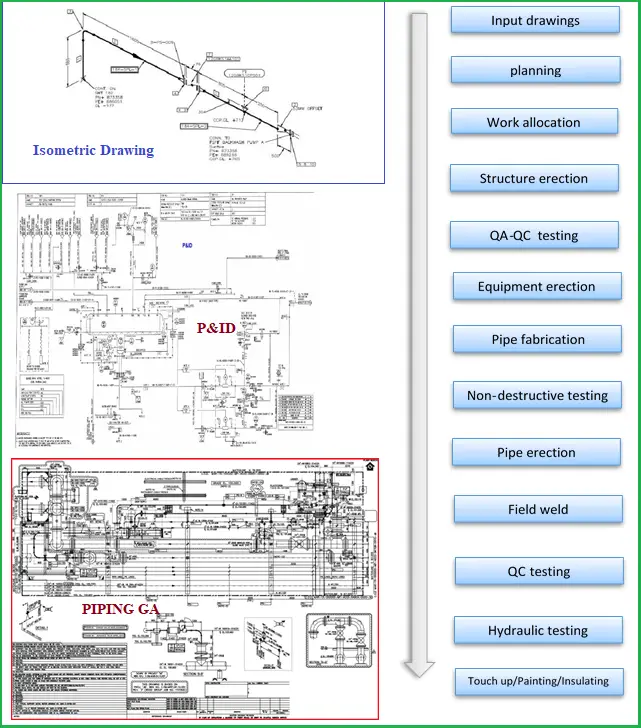
P&ID is the heart of piping; it includes pipeline number, size, material, and insulation; Process condition & physical data, operation condition, streamflow details, Equipment numbers, etc.
Piping Isometric drawings include proportionate drawings with exact dimensions represented, line numbers, pipe fittings, valves, flanges, special components, tables including a list of all fittings in the drawings, etc.
Piping GA drawings include the locations of the main equipment in the plant, main piping items, fittings and valves, nozzle orientation of the concerned equipment, etc. Fig. 1 below shows typical drawings required for piping installation and a piping erection and installation flow chart.
Piping Installation Procedure
Piping Installation normally starts after civil supports are erected and major types of equipment are placed on the construction site. The installation of piping can be grouped into the following parts:
- Pipework Erection
- Installing Piping Flanges, Valve, and equipment Flange Connection
- Installing pipe Supports
- Pressure testing
- Insulation and Painting
- Marking and Identification
- Installing Expansion Joints
- Vents and Drains
- Underground Pipe Installation
Pipework Erection Procedure
Proper planning should be made to erect piping, area-wise following piping isometric and GA drawings. The following piping erection guidelines should be followed:
- All tools, equipment, ropes, and pipes must be inspected and certified by HSE guidelines before erection to ensure that they are safe and ready, clean, and free from loose contamination.
- Pre-fabricated spools need to be identifiable and numbered/tagged.
- Pipework should be erected on supports designated for the specific line. Primary pipe supports can be welded prior to erection following pipe support drawings. The number of temporary supports shall be minimized.
- Undue stresses should not be applied to force the piping to keep it in the proper place.
- To avoid the ingress of moisture and foreign matter, pipe openings should be sealed during erection.
- Installation of piping on pipe racks should be done from lower elevation to higher elevation.
- Large-bore piping shall be installed prior to small-bore piping.
- Piping Joints shall be properly aligned.
- Pipe clearances from other pipes, equipment, and structures should be maintained.
Installing Piping Flanges
Clean pipe flanges should be brought up flush and square without forcing them to bear uniform bolt tension and gasket compression. Line items like orifice flanges, spectacle blinds, strainers, etc. shall be installed following proper orientation. A logical bolt tightening (hydraulic bolt tensioning & torque tensioning) sequence needs to be followed.
The flange connections to this equipment shall be checked for misalignment, excessive gaps, etc. Until both side flanges are ready for mating connection, flange covers shall be retained on all flanged connections to the valve or equipment.
Extra care is to be exercised for flange connections to pumps, turbines, compressors, cold boxes, air coolers, etc. Blanks or spades should be used on equipment to prevent the ingress of internal pipe debris. Bolting shall move freely through accompanying bolt holes at the right angle to the flange faces and a clear gap between the two flange faces for the gasket needs to be maintained before gasket installation.
Pipe Support Installation
- Relevant pipe support detail drawings should be used for installing pipe supports.
- Additional stress should not be introduced to fit the supports.
- The pipe shoe should be installed at the center of the beam without any offset.
- Where spring supports are required, those should be locked until hydro testing and insulation. Manufacturer installation guidelines should be followed.
- Where PTFE plates are used for friction reduction, the ingress of sand in between SS and PTFE plates should be avoided.
- Piping is to be arranged to facilitate pipe-supporting and shall be well-planned for ease of removal of equipment for inspection and servicing.
Pressure Testing
Following the guidelines, hydrostatic or pneumatic testing should be performed to check the system’s integrity. In case of leakage, those are repaired and re-tested again. Click here to learn more about Pressure testing
Insulation and Painting
After pressure testing, bare pipes and painted as per specification. High-temperature lines are insulated following the insulation procedure.
Marking and Identification
All pipes and fabricated fittings are marked on their outside with letters and numbers for easy identification of lines, their services, etc. Marking is normally done by stamping, tagging, stenciling, or using any other permanent marking method.
Installation of Expansion Joints
Expansion joints are normally required for critical piping systems. Bellows should be installed following the vendor’s guidelines and installation drawings. Piping should be perfectly aligned with the expansion joint as mentioned in the detailed drawings.
Vents and Drains
Ideally, vents and drains should be located in the isometric drawing or GA drawings. In case, high-point vents and low-point drains are not provided in those drawings, these should be provided as per the instructions of the Engineer-in-Charge/Job standards/ Piping Specifications.
Installing Underground Pipes
- Before starting buried pipe installation, it must be ensured that trench excavation is done following the approved drawing.
- Final measurements, tests, and surveys are to be completed before backfilling.
- The depth of cover as mentioned in the GA drawings should be maintained.
Equipment and Tools for Pipe Erection
The following equipment and tools are used for piping erection and installation purposes.
- Welder’s gauge
- Pipefitters square
- Fitter grips
- Centering head
- Flange aligners
- Pipe wraps
- Pipe clamps
- Pipe cutter
- Pipe stands
- Water hose
- Welding machine
- A-frame
- Adjustable wrench
- C clamp
- Center punch
- Chain block
- Forklift
- Steel tape
- Tower crane
- Boom lifter
- Cranes
- Spanners and Torque Wrenches
Safety during Piping Installation
“SAFETY FIRST” is the primary concern of engineers. Hence, the safety of the people should override all other targets and achievements. Any unsafe situation should immediately be reported to the HSE manager and the work should be postponed. So the following guidelines should always be observed during piping installation and erection.
- Identifying the hazards associated with piping services. This is mainly concerned while working in operating plants.
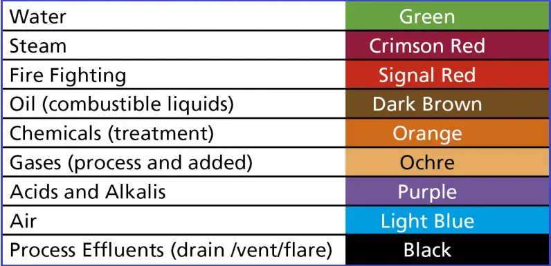
- Understanding the color codes: Pipes are normally colored following standard guidelines to identify based on fluid service categories. The following image (Fig. 2) provides a sample color-coding table based on the BS 1710 standard.
- Exercise extra care while tying a pipe to an operating system.
- Use proper safety guidelines while working at heights and confined spaces.
- Always be aware of what can go wrong and what to do if things go wrong.
- Personal safety equipment must always be carried.
Thanks for sharing good information.
Thanks for the good guidelines
This post will be very useful to us. I like your blog and helpful to me. nice thoughts for your great work.
Thank you very much.. information is helpful.
Very rich information. Thank you for such content. You have very well presented it here in a simple and understandable way. Well done.
i need burried pipe installation procedure
Installation and erection notes
Am great full to hear that information and need more about pipeline engineering
thanks for sharing revelant details on piping installation and erection. It is so useful and excellent work out.