
A restriction orifice is a device designed to control the flow of fluids by introducing a deliberate constriction in the flow path. It functions by reducing the diameter of the pipeline at a specific point, which results in a pressure drop and flow restriction. Typically, a restriction orifice is a simple, plate-like device with a precisely machined hole, but its impact on the flow characteristics of a system is substantial. In this article, we will describe the significance of restriction orifices, their functionality, working, types, applications, standards, and steps for their design.
What is a Restriction Orifice (RO)?
Restriction orifice or RO, in short, is a flow control instrument device whose primary function is to provide a restriction to the flow so that a controlled or restricted flow is achieved. Due to this restriction by the orifice plate, a pressure head drop from the upstream of the orifice to the downstream is observed. For a specific temperature and pressure condition, the orifice area at the outlet determines the volumetric flow rate of the fluid inside the pipe. Due to the high-pressure drop at the restriction orifices, it can create acoustic-induced vibration. Hence, studies must be performed by specialists.
The orifice plate is basically a thin plate with an orifice in the middle. The plate is inserted between two flanges of a pipe for providing restriction or flow measurement.
Purpose of Restriction Orifice
Restriction Orifice is used primarily for two main reasons:
- If there is a requirement for Reduced flow or
- If there is a requirement for high-pressure drops.
The device is sized depending on the required pressure drop. They are designed to slip between the piping flanges. Restriction orifice comes with single restriction orifices or multiple restriction orifices in Series.
How Restriction Orifices Work?
The fundamental principle behind a restriction orifice is based on fluid dynamics. When a fluid flows through a constricted area, its velocity increases, and its pressure decreases. This is described by Bernoulli’s equation. By selecting an orifice of appropriate size and shape, engineers can precisely control the flow rate and pressure drop across the orifice. It is calibrated based on the installation’s technical requirements to achieve the correct pressure or flow rate. Depending on the needed values, either simple restriction orifices (with one or multiple holes) or multi-stage restriction orifices can be used.
Applications of Restriction Orifice
Engineers and designers are familiar with a restriction orifice in the following applications for impeding flow or reducing pressure.
- They are installed downstream of blowdown valves to ensure a controlled flow rate in the blowdown piping or blowdown header.
- They are installed in the minimum flow bypass lines around centrifugal pumps.
- They are installed in Wellhead applications
- A restriction Orifice is sometimes used to restrict excess flow in case ruptures.
- Minimum bypassing
- Injection, cooling, and flushing of fluid.
- Sampling.
- The steam let down.
- Use as a simple static mixer
- N2 purge or constant gas seal
- Controllability improvement
Restriction Orifice Standard
There is no direct standard addressing the design of restriction orifice, but some associated references are available as listed below:
- ISO 5167 Part 1 and Part 2
- ISA RP 3.2
- API -RP 550/551
- API 2531
- IEC 60534-8-3
- API Manual of Petroleum Measurement – Chapter 4
- AGA Report No.3
- API MPMS 14.3.2
- ISO 5024
- ISO 5168
Working Principle of Restriction Orifice/Orifice Plate
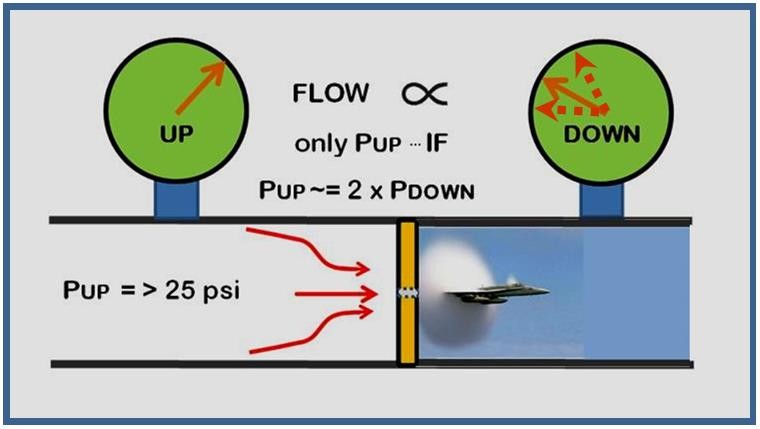
Both Restriction Orifice and Orifice plate work following Bernoulli’s principle that states that pressure drops across the restriction orifice are directly proportional to the volumetric flow rate passing through the orifice plate.
While fluid flows through the plate, fluid velocity changes that in turn, as per Bernoulli’s equation change the pressure. This change in pressures upstream and downstream is measured to calculate the volumetric flow rate.
Restriction Orifice Types
Restriction Orifice Plates are of three types
Single-Stage Restriction Orifice:
A plate with an orifice bore of the required size for intended pressure loss is known as a single-stage restriction orifice.
Multi-hole Single Stage Restriction Orifice:
To reduce the noise generated, single-stage multi-hole restriction orifice plates are used. As the high-velocity flow at the RO inlet is distributed through several holes, the noise is reduced. To avoid the cavitation problem, multi-hole restriction orifices are used. The flow distribution through multiple holes improves the cavitation factor which in turn reduces the overall noise.
Multistage Restriction Orifice Assembly:
Multistage restriction orifices are widely used for very high-pressure reduction when a single-stage RO is not capable. It consists of a number of single-stage RO devices. The design can be single-hole or multi-hole. The restriction orifices in a multistage RO are usually arranged in an eccentric manner. The minimum distance between each stage is usually the internal diameter of the pipe.
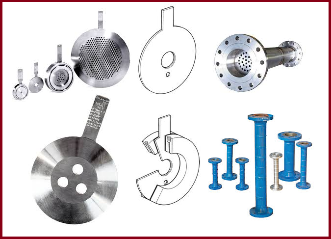
Types of Orifice Plates:
The plates used in restriction orifice design can be of the following types:
- Square edge bore or standard bore orifice plate.
- Quadrant edge bore
- Eccentric bore orifice plate
- Segmental bore orifice plate
- RTJ-type orifice plate with an integral gasket
- Paddle-type orifice plates
Inputs for Restriction Orifice Design
The following inputs are required for the design of the restriction orifice:
- PFD and P&ID
- Hydraulic Calculation Sheet
- PMS
- Line operating conditions like upstream-downstream pressure, temperature, flow rate, line size, Density, Viscosity, molecular weight, Cp/Cv, vapor pressure, etc.
Restriction Orifice Design Steps
Based on the service and requirements, RO needs to be sized for critical or pre-critical conditions. During sizing, the pressure control RO plates consider the maximum pressure drop lesser than the critical pressure, and flow control RO plates consider the critical pressure drop. ISO 5167 is generally followed for sizing restriction orifices.
The design of the Restriction orifice or RO is carried out as per the steps similar to as mentioned below:
- Determination of Application
- Data Preparation for the orifice
- Restriction orifice sizing (by design engineer or vendor)
- Checking of critical design elements like cavitation index (Kc=0.93), pressure drop, minimum orifice diameter, allowable space in piping routing, etc.
- Filling out the necessary information in P&ID and RO datasheets
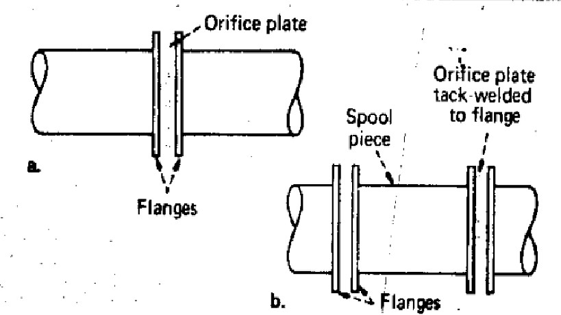
Installation of Restriction Orifice
The restriction orifice is physically a thin plate with one or more holes in it. In piping application, They are normally inserted in between two flanges. It is possible to inadvertently leave out the plate when the piping is assembled, or, more likely, to forget to replace it when the piping is reassembled, following maintenance or cleaning. So leaving out the orifice is difficult.
Safe solution
To prevent this, one should make it impossible to assemble or reassemble the piping without including the orifice. A simple, practical, and foolproof method are: the restriction orifice has its own spool piece. So in such a situation, there will not be scope for forgetting the RO element during installation or Construction.
Orifice upstream and downstream requirements
It is a standard engineering practice to keep 10 pipe diameters (10D) upstream (before the orifice) and 5 pipe diameters (5D) downstream of the restriction orifice.
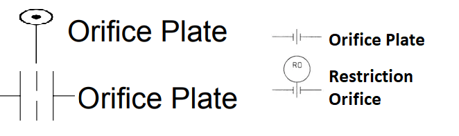
Restriction Orifice Symbol
The following symbols are used in P&ID to describe restriction orifice and orifice plates.
Restriction Orifice vs Orifice Plate
The major differences between the Restriction orifice and orifice are tabulated below:
| Restriction Orifice | Orifice | |
| Purpose | A restriction Orifice is used for killing the high pressure or reducing pressure; a pressure-reducing device. | An orifice is used for flow measurement. |
| Hole Profile | The hole of the restriction orifice has a straight profile | The hole profile of the orifice is straight at first but then beveled (notched) with a 45° slope |
| Pressure Drop | Restriction Orifice causes High-Pressure drop | The pressure drop in a normal office is low. |
| Fluid Velocity | Restriction orifices work on sonic Velocity to ensure choked flow. | The flow through the orifice is a subsonic flow. |
| Acoustic Induced Vibration | Restriction Orifice is highly Susceptible to AIV and high noise can generate | Flow through usual orifice plates is not Susceptible to AIV. |
Factors for Sizing RO device
There are various factors that must be considered while sizing restriction orifice.
Pressure Drop:
For sizing and selecting the restriction orifice, the pressure drop is a critical parameter. The required minimum thickness of a RO device is dependent on the pressure drop across the device.
Flow Rate:
As the pressure drop is dependent on the flow rate changes, the restriction orifice needs to be sized for a normal flow rate. For critical RO, the downstream flow rate should be considered.
Sonic Flow:
Choked or sonic flow conditions may arise due to a decrease in density and an increase in velocity when a gas accelerates through a restriction. A Sonic flow in the pipeline generates high noise and vibration in the pipeline that may cause mechanical failure. To avoid this, the maximum pressure drop across a single-stage restriction orifice plate must be limited to a critical pressure drop.
Cavitation:
In liquid flow restrictions with very large pressure drops, cavitation may occur. While passing through the restriction orifice, the velocity of liquid drops, and pressure increases. Due to these, vapor bubbles can collapse and flashing can occur. this phenomenon is known as cavitation. To avoid cavitation, the restriction orifice should be sized to maintain the cavitation index less than the incipient cavitation index of the RO plate. Inlet pressure, outlet pressure, and vapor pressure are the parameters for the cavitation index, and the incipient cavitation factor will be dependent on the beta ratio of the plate.
Noise Level:
Noise levels in RO can be predicted by calculating sound power generated due to pressure reduction. Next, the transmission losses can be subtracted to find the sound level at any pre-decided location. To reduce the noise in the restricted orifice, the following options can be selected when sizing.
- Reduction of the pressure drop.
- Increase the number of stages of reduction.
- Using multi-hole RO plates.
- Optimizing the pressure drop across each stage.
- Increasing the margin between the cavitation index and incipient cavitation index.
Click here to know the sizing procedure of restriction orifices for single-phase fluids
Reference: CHEMICAL ENGINEERING/ APRIL 13, 1987
About the Author: Part of this article is written by Mr. Amir Razmi, an International, dynamic, and multi-functional chemical engineer with 16+ years of experience in engineering and EPC of oil and energy projects from pre-contract activities to execution, and closeout.
NIce continued.
Hi, nice venture, if you require help on any other subject, please feel free to ask.
Hi sir thank you for this helpful information and the effort you spend it on this information
i have one question can we replace the control valve and restriction orifice into choke valve in the venting system of natural gas station, I’m waiting for your response sir
many thanks
Thank you please, can you help to know what formula to use to calculate the reduced flow rate after the restriction orifice?
how much space should we provide between upstream and downstream
Hello Sir. My question is, if the pipe is 150#, does the RO need to be higher rating (300#) ?
Good day, sir.
Are there restriction orifices in a refinery?