Hydrogen Induced Cracking (HIC) is a form of wet H2S cracking that is usually generated by high hydrogen concentration in metals. The mechanism involves atomic hydrogen which diffuses into a metal structure. The cracking due to HIC is formed parallel to the surface in the hoop stress direction. Hydrogen-induced cracking is more prevalent in sour service environments due to the presence of wet H2S. There are some other elements that may contribute to hydrogen-induced cracking. Some of these elements are arsenic, antimony, selenium, and cyanides. However, H2S is considered the most contributing element to hydrogen-induced cracking damage in the oil and gas industry. HIC causes blistering damage to many metals and alloys.
Hydrogen-induced cracking is more common in ferrous alloys due to its restricted slip capabilities in its BCC structure. HIC, in general, causes damage to steels with Rockwell C hardness of 22 or more at relatively low temperatures.
HIC can also occur during various elevated temperature processes like electroplating, pickling, phosphating, cathodic protection, arc welding, etc.
API Nelson curve provides a basis to understand the temperature zone over which the possibility of HIC increases. A typical curve indicating the HIC and Non-HIC zone is provided in Fig. 2 of the Sour Service article. Click here to refer to that article.
What is Hydrogen-Induced Cracking?
HIC = Hydrogen Induced Cracking = Caused due to Hydrogen attack on metal
Hydrogen-induced cracking is also known as
- Hydrogen Damage
- Hydrogen Embrittlement
- Hydrogen Blistering
- Delayed Cracking
- Lamellar Tearing
- Underbead Cracking
- Stepwise Cracking
Hydrogen Induced Cracking Mechanism
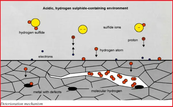
In a wet H2S environment, the HIC mechanism starts with the formation of atomic hydrogen that diffuses throughout the metal or alloy that collects at voids or impurities within the metal structure. When these hydrogen atoms combine to form a hydrogen molecule, it produces high pressure within the cavity. The H2S forces these hydrogen atoms into the metal structure which in turn reduces the ductility and tensile strength of the metal. Slowly, this mechanism reduces the metal ductility such that stepwise internal cracks are formed which is known as hydrogen-induced cracking.
Refer to Fig. 1 which shows the mechanism of HIC.

Exhibit – Hydrogen-Induced Cracking
HIC is often visible on the metal surface as horseshoe-shaped. Regular inspection and testing need to be performed for eliminating the possibility of hydrogen-induced corrosion. The damages by HIC can be detected by Wet Fluorescent Magnetic Particle Inspection. For cracked components Phased Array Ultrasonic Testing is the most widely used and reliable non-destructive method.
Low alloy steels and high-strength titanium and nickel steels are more prone to hydrogen-induced cracking. Low-strength steels with tensile strength below 1000 MPa are usually not susceptible to HIC. Copper, Aluminum, and their alloys are the most resistant to HIC.
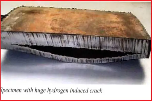
Fig. 2 shows an example of a crack by HIC.

Requirement of HIC Resistant Materials
Requirements for Carbon and Low Alloy Steels
- The hardness of the Parent Material is Less Than 22HRC (237 BHN)
- The steel shall be fully killed ( Silicon/Aluminum)
- The material should be Heat Treated by NORMALIZING / ANNEALING / Q AND T
- Carbon content shall be less than 0.23% and Carbon Equivalent (CE) less than 0.43
- Sulfur and Phosphorus less than 0.002%
- Requirements like Calcium Treated, Inclusion Control.
Requirements for Austenitic Stainless Steel
- Hardness on Parent Materials less than 22HRC (237 BHN).
- Heat Treated by Solution Annealing.
Requirements for Duplex and Super Duplex Stainless Steel
- Hardness on parent Material less than 25 HRC.
- Heat Treated by Solution Annealing.
- Ferrite shall be 35% to 65%.
Hydrogen-Induced Cracking Test
HIC test is performed following NACE TM0284. The unstressed HIC test specimen is exposed to the specified process environment saturated with hydrogen sulfide gas at 1 bar pressure for a duration of 96 hours (4 days) for the standard test. Fitness for purpose of testing is performed for durations of up to 30 days using reduced partial pressures of hydrogen sulfide.
Once the exposure period is finished, the test specimen is examined and any cracks developed are measured. The usual ratios that are used for hydrogen-induced cracking tests are the Crack Sensitivity Ratio, Crack Length Ratio, and Crack Thickness Ratio.
There is one more HIC test method known as Stress Oriented Hydrogen-induced cracking (SOHIC) test method. SOHIC test is performed following NACE MR0175 or ISO 15156 using the full ring test method as mentioned in BS 8701, tensile test method as mentioned in NACE TM0177-Method A, or four-point bend method as mentioned in NACE TM0316.
Few more Resources for you..
Guide for Coating Selection for External Bolting to Reduce Corrosion
Corrosion Monitoring Techniques & Surveys
Corrosion Protection for Offshore Pipelines
Forms of Corrosion: An Article
Corrosion under insulation: A Presentation

Great topic and easy reading to understand HIC. Please continue great job Anup.