
Piping Isometric drawing is one of the most important deliverables of the piping discipline as it provides complete information of the piping route to be erected at the construction site. So Engineers and Designers must be aware of the isometric preparation steps. In this article, a few of the salient points are discussed.
- Piping isometrics are the three-dimensional representation of the line.
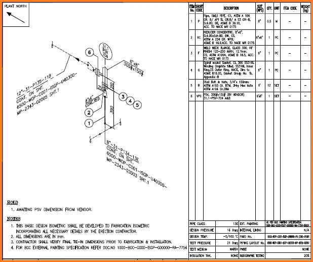
- The main purpose of an isometric is to provide all information necessary for the fabrication and erection along with the bill of material required to do so.
- Isometric is also used to work out the exact MTO requirement.
- Generally, isometrics are prepared/extracted by the design group.
- A draft person (piping designer/engineer) who knows to read the piping GA. and is conversant with a drafting tool can draft isometric.
Input required for piping Isometrics
- Piping Plan
- Piping Specification
- Line List (Process)
- Latest P&ID/PEFS (Process) (Issued signed copy)
General Information about Piping Isometric drawings
- An isometric drawing covers a complete line as per the line list and P&ID. It shows all information necessary for fabrication and erection.
- Isometrics are not drawn to scale but should be proportional to easy understanding.
- Dimension is given relative to the centreline of the piping.
The following information must be included in piping isometric drawings:
- Plant North: The direction should be selected so as to facilitate easy checking of isometrics with GA.
- Drawing number & revision.
- Reference number of PEFS (P&ID), GA drawings, line numbers, the direction of flow, and insulation tracing.
- Design pressure, design temperature, test pressure, testing medium, radiography requirement, Heat treatment requirement, painting requirement, and internal coating requirement.
- Coordinates of equipment against equipment layout.
- Equipment number & appearance on the isometric drawing.
- Line specification changes.
- Scope breaks.
- Changes in the direction and angles of the line should be clearly shown.
- Representation is correctly made in line with the standard symbols.
- Location and identification of all instruments.
- Requirements of upstream/downstream straight lengths. Insulation requirements as per PEFS (P&ID).
- Details and section identification match.
- “Match line” provision and accuracy.
- Accuracy of BOM in Isometrics.
- Weld points & field welds.
- Insulation class, Insulation thickness & Flow direction are indicated.
- Give the details of the flange on the equipment if the specification is different from the connecting piping.
- Size and type of every valve/direction of operation.
- Size and tag of the control valve.
- Field weld– Location.
- High-point vents and low-point drains.
- Special support like support from flange or welded supports details to be shown.
- If the line is stress-critical, stress analysis results are incorporated.
- All the symbols are used as per Legend.
- Slope showed as per P&ID/PEFS.
- Spectacle blind, spacer, and blind open/close position as per PEFS/P&ID.
- High-point vents and low-point drains have been provided for lines that will be hydro tested. (e.g. Instrument Air, Flare, and Nitrogen lines may not be hydro tested, but pneumatically tested).
- Orifice tapping orientation is as per instrument standards for gas and liquid lines.
- Flow direction for items such as check valves, globe valves, strainers, etc. is clearly marked.
- Isometric issued for Re-IFC to be marked with cloud and revision triangle.
- Insulation gasket demarcation is to be shown.
- General notes.
- Bill of Material.
- Tie-in numbers.
Checking of Piping Isometric Drawings
Checking Piping Isometric Drawings before finally releasing them to the Construction team is very important. It minimizes errors and improves quality. Most of the design companies involved with isometrics prepare a piping isometric drawing checklist or isometric checklist to help Piping Isometric Checker in their activity. Also, many times piping isometrics are extracted directly from Piping Design Software. It is mandatory for the Senior Piping Checkers to check the piping isometrics thoroughly. In the tight schedule, It has to be ensured that the isometric drawings are released/ issued to clients with quality.
Checking shall be done only on a hard print as per the color code procedure by an experienced engineer/designer. Normally checklists are followed to ensure the quality of the isometrics. The new print after correction is “back checked” for incorporation.
In the following paragraphs, We will provide a few checkpoints which must be checked by the piping isometric checker for proper quality.
Piping Isometric Checklist
A Piping isometric checklist is a list of checkpoints that are ensured while checking the piping isometric. A piping isometric checker must ensure the correctness of the below-mentioned points in the piping isometric
- Line numbers (nos.)
- Line specifications
- Start point location
- Endpoint location
- Branch connection
- Piping Reducers
- Piping spec break in the proper location as per P&ID, if any (preferably be at flange joints/valves, each isometric (iso) to contain only one spec).
- Valve accessibility
- Support location
- Insulation (for the insulated line only)
- Instrument connection
- Flow arrow
- High point vent, low point drain
- Hydro test vent and drain
- Equipment nozzle connection
- Nozzle numbers.
- Equipment numbers.
- Coordinates and elevations
- North direction
- Bill of material
- Valve tag numbers.
- Instrument tag numbers.
- Continuation sheets or isometric numbers.
- Grid location and numbers.
- Tag numbers of special items (if applicable).
- Slope/no pocket/free draining requirement, if any.
- Minimum or Maximum distance, straight length requirements, etc. as specified in P&ID.
- Close/open position for spectacle blind or spacer & blind.
- Removable spool pipe requirement, if any.
- The sequence of branch connections (as agreed with Process in case of any changes).
- The special feature of valves (e.g. LO, LC, etc.)
- Insulation symbol for insulated lines.
- Insulating gaskets are selected as shown in P&IDs
- Specific requirements mentioned in applicable P&ID notes (if any) have been complied with.
Documents Required for isometrics checking
Before starting the piping isometric checking activity, the engineer must be ready with the following drawings or documents
- Piping and instrument diagram (P&ID): From this drawing, we will get information like line number, line size, insulation, fluid commodity, special notes (like no pocket, requirement of spectacle blind in equipment nozzles, pressure head, specific straight length requirement for instrument connections), etc.
- Piping layouts and Sectional Drawings: Piping layouts will provide information on the pipe route, dimension, elevation, valve orientation, and coordinates.
- Equipment drawings: To check details of lines connected to equipment nozzles, their elevations, etc.
- Nozzle orientations: To ensure the nozzle elevation and orientation is proper.
- Piping material specification: for checking piping materials and based on that if any special requirement is there. For example, piping supports in galvanized or internally PE or ROTO-lined pipes should not be welded.
- Piping support standard: To understand and check proper support selection in the piping isometric drawing.
- Special items drawings: For verifying the dimensions of special items.
- Stress analysis report: To review if all the stress comments have been updated in piping isometric or not.
- Instrument Hook-up Details: To ensure the end connection requirements for mounting the instruments are in order.
Points to remember while piping isometrics checking
- The pump suction is bigger than the discharge line (Refer to P&ID)
- The eccentric reducer (flat side top) used for the pump suction line is used for avoiding the air block in pump suction.
- The pump suction line and compressor suction line keep always a downward position, Avoid loops in pump suction.
- The “Continuation on …” description correctly appears at each end of the line isometric which is continued in another sheet.
- PSV outlet is always in a rising position.
- Check the valve accessibility for maintenance purposes. The valve operating height min 250 mm to 1200 mm from floor level.
- Lift check valve always horizontally using. Swing check valve vertically and horizontally using.
- Isometric number change is made preferably at a flange joint/valve (not at a weld joint).
- Control station operating height 500 mm to 750 mm from floor level.
- Pipe Shoe not required for trunion. (insulated lines)
- Headroom clearance minimum 2.2m from ground/floor level.
- Drip leg required for steam line header.
- Shoe required for insulated lines (steam, chilled water, brine, steam condensate).
- Nozzle orientations should be kept as per the piping requirement.
- Avoid obstacles. Keep piping routing neat and clear.
- Control stations locate the side of near the walls or columns
- Give support to the control station both sides of the control valves.
- Use a dike wall around the equipment to avoiding the liquid to spread in the plant area. the volume of the dike wall is 1.5 times more than the total capacity of the equipment.
- Use weld neck flange for pressure piping.
- The isometric numbering is as per the approved project format and the line number matches with the isometric number.
- Adequate pipe spool lengths are provided for wafer type butterfly and check valves to prevent the interference of the valve disc with adjacent piping items.
- The platform/grade/building wall/dike or bund wall/floor penetrations and limits of road crossings are properly shown wherever applicable.
- The insulation limits are specified appropriately (esp. for heat conservation or personal protection)
- The electrical tracing requirement and its limits are specified appropriately.
- The wrapping and coating requirement and its limits are specified appropriately for u/g lines.
- The minimum distance between welds is 50mm or five times the wall thickness whichever is greater unless otherwise indicated in Project specifications.
- Unions are provided in galvanized piping where threaded in-line items need to be removed for maintenance. Also, unions are provided at regular intervals (e.g. 24m) in straight pipe runs.
- Full couplings are provided where applicable for small-bore piping.
- For piping below 2”, Weld Neck flanges are not directly welded to Socket Welded fittings. Also, PE pipes are not directly welded with swaged reducers (pipe couplings are used in between).
- Appropriate break-up flanges are provided in piping with internal lining and hot-dip galvanized piping (based on tub size). The spool configuration is made with one elbow or one tee only to ensure proper galvanizing.
- Lifting lugs are provided for removable spools wherever required as per project requirements.
- There is adequate clearance between pipe support and the adjacent piping component (e.g. flange, drain valve) to allow for flange bolt removal, valve operation, etc.
- The valve stem orientation angle is indicated wherever the stem is not in the vertical and horizontal planes.
- The piping interfaces with equipment/package nozzles/terminal points are checked (w.r.t. size, rating, flange face type, and nozzle/Tie-in Point nos.).
- The straight length requirement for suction & discharge piping for compressors and certain pumps is as required by Vendor/project specs.
- Straight lengths and branch configuration of upstream/downstream lines for anti-surge valves are as per the Compressor Vendor’s recommendation.
- The Face to face dimensions of all valves, piping special items, and in-line instrument items are as per approved vendor drawings.
- The instrument connections are checked with Piping-Instrument interface drawings/Instrument hook-up drawings.
- The rotameters are installed in the vertical run with the flow in an upward direction.
- The orifice tapping orientation is done considering liquid or gas flow as applicable and the BOM is as per the piping-instrument interface diagram.
- The straight length requirement (u/s & d/s) has been provided for flow meters (e.g. flow orifices, flow nozzles, venture meters) and is as per Project standards/Vendor requirements.
- The line configuration for lines containing magnetic flowmeters or vortex type flowmeters is such that they are always flooded.
- Line configuration allows easy removal of spectacle blinds/spacers & blinds and valves in the case of RTJ flange joints.
- Flanged spools are provided in the case of conical strainers to enable removal.
- The orientation of valve handwheel/lever is checked in model for proper access and commented accordingly
- Line routing is visually checked in the model for general requirements like access to inline items, supporting, clearances, obstructions, consistency and aesthetic requirement, etc.
- Branches like drains, drip legs, etc. are located with sufficient clearance from the supports, steel, or other obstructions so that they do not clash during expansion/contraction.
- Drip leg size and dimensions are checked with Standard drawing for steam lines.
- The requirement of Weep holes for atm vent lines is indicated.
- The drawing border conforms to the Project specifications or Company standards, as applicable.
- The correct isometric revision number is mentioned in the title block.
- Pipe class printed at the bottom of the drawing matches that in the line number.
- Line data (e.g. process parameters, P&ID no., PWHT & testing requirements, insulation & painting specs, etc.) match with the Line List, if given in the isometric
- Applicable reference documents (e.g. Line List, Isometric Index, Pipe Supports Spec, etc.) are mentioned.
- Data such as inch-dia, inch-meter, etc. appear at the bottom of the isometric.
- The isometric print is readable (if required, the isometric should be split into more sheets).
- Dimensions and elevations are adequately given. At least one elevation is mentioned and WP elevations for sloped lines are marked.
- There are no HOLDs in the isometric (issue of any isometrics with HOLD requires approval by HOD/PEM).
Online Video Course on Piping Isometrics
If you wish to explore more about piping isometrics, you can opt for the following online video course
- Piping Design Engineering and Piping Isometrics Masterclass
- Piping Isometrics Demystified
- Piping Fabrication with Isometrics
Video Tutorial on Piping Isometric Drawing
Refer to the following video tutorial for a better understanding of piping isometric drawing.
Few more useful resources for you.
Piping Design Basics- Isometric Drawings
Types of Piping Drawings
Salient Points to check while reviewing Piping Isometric Drawings
Major points
1. Nozzle co-ordinates
2.vessel clip orientation given to mech.
3.orientation of gate valve on steam PSV outlet
Thanks a lot for sharing your in depth knowledge in piping.
Can you send me Pdf?
Thanku so much sir.
Can you send me pdf?
Great, keep going.
There is a statement concerning check valves which I found confusing.
A swing check valve should always be installed horizontally.
A piston or lift check valve may be installed horizontally or vertically.
A Dual Plate check valve may be installed vertically provided it has been sized correctly and there is adequate flow to ensure opening.
Instrument Hook-up Details: To ensure the end connection requirements for mounting the instruments are in order.
could you provide the code requirement showing that order of instruments connections matters and must be per P&ID?
Can u send pdf
Thank you somuch sir, its valuable information to me.
I need knowledge of ISO piping drawing. And piping installation. Thanks