Carbon monoxide (CO) is a colorless, odorless, and tasteless toxic gas that exists in minute concentrations in the atmosphere, typically less than 0.001%. Despite its seemingly benign presence, carbon monoxide poses a significant threat to human health and safety. In 2020 alone, there were 200+ reported deaths attributed to carbon monoxide poisoning, underscoring the urgent need for awareness and preventive measures.
What is Carbon Monoxide Poisoning?
Carbon monoxide poisoning is a medical condition that occurs when an individual inhales an excessive amount of carbon monoxide (CO) gas, leading to its accumulation in the bloodstream. This harmful gas is produced as a result of the incomplete combustion of carbon-containing materials, such as wood, gasoline, natural gas, and other fossil fuels. Carbon monoxide has a high affinity for binding with hemoglobin in red blood cells, forming carboxyhemoglobin (COHb) and preventing oxygen from binding to hemoglobin. This reduces the blood’s ability to transport oxygen to body tissues, which can lead to a range of symptoms and, in severe cases, can be life-threatening. Symptoms of carbon monoxide poisoning can include headaches, dizziness, nausea, vomiting, weakness, confusion, and, at high levels of exposure, unconsciousness or death. Immediate treatment typically involves removing the affected person from the source of carbon monoxide and administering oxygen therapy to restore oxygen levels in the bloodstream.
Carbon monoxide poisoning occurs when individuals are exposed to elevated levels of CO gas. The insidious nature of this poison lies in its stealth – it cannot be seen, heard, or smelled, rendering it devoid of warning signs. This silent killer is a byproduct of the incomplete combustion of carbon-based materials, such as kerosene, natural gas, wood, coal, gasoline, and more. When combustion occurs with insufficient oxygen, carbon monoxide is generated, further emphasizing the need for vigilance.
Sources of Carbon Monoxide in the Workplace
One may be exposed to unsafe levels of Carbon Monoxide in workplaces by:
- poor industry maintenance or unvented heating equipment;
- poorly vented natural gas burning equipment;
- vehicles in garages (car engine exhaust fumes) or other enclosed spaces;
- during a plant fire (smoke from fires); etc.
Other sources may include the use of charcoal fire grills in confined spaces (e.g. tents). Poorly installed domestic gas heating appliances and incomplete combustion of butane and propane (e.g. in caravans) may lead to sub-acute, chronic, or occult poisoning.
Some of the sources of carbon monoxide are:
- Generators
- Concrete cutting saw
- Welding fumes
- Clogged chimney
- Gas heaters
- Corroded or disconnected water heater vent pipe
For example, assume that one man is working in a small enclosed non-ventilated room with a fired heater, and complaining of dizziness, severe headache, nausea, weakness, angina is chest pain. He is a patient with Carbon Monoxide poisoning.
Signs and Symptoms of Carbon Monoxide Poisoning
Carbon monoxide (CO) poisoning can present with a range of symptoms, and the severity of these symptoms can vary depending on the level and duration of exposure. Breathing CO can cause headaches, dizziness, vomiting, and nausea. If CO levels are high enough, one may become unconscious and even die. Exposure to moderate and high levels of CO over long periods of time has also been linked with an increased risk of heart disease. People who survive severe CO poisoning may suffer long-term health problems. Sleeping or drunk people can even die from carbon monoxide poisoning before showing any symptoms.
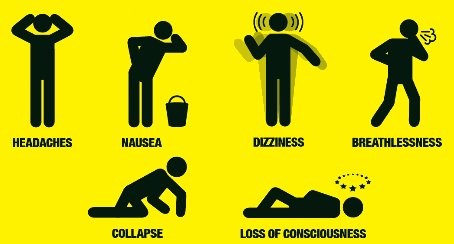
Here, we’ll explain the top 5 symptoms of carbon monoxide poisoning in detail:
Headaches:
Headaches are one of the most common and early symptoms of CO poisoning. These headaches can be persistent, throbbing, and often described as more intense than regular headaches. They are a result of the reduced oxygen supply to the brain due to the binding of carbon monoxide to hemoglobin, which diminishes the brain’s access to oxygen.
Explanation: When CO binds to hemoglobin in the blood, it forms carboxyhemoglobin (COHb), which reduces the blood’s oxygen-carrying capacity. This reduced oxygen delivery to the brain can lead to headaches.
Dizziness and Lightheadedness:
Individuals exposed to elevated levels of carbon monoxide often experience dizziness and a sensation of being lightheaded. This can make them feel unsteady on their feet and affect their coordination.
Explanation: Reduced oxygen supply to the brain impairs cognitive function and balance, leading to dizziness and lightheadedness.
Nausea and Vomiting:
Nausea and vomiting are common symptoms of CO poisoning. The sensation of nausea can be intense and may lead to vomiting. These symptoms are often mistaken for gastrointestinal issues.
Explanation: CO poisoning can affect the gastrointestinal system and trigger nausea and vomiting. These symptoms can further contribute to dehydration, as affected individuals may not be able to keep food or fluids down.
Weakness and Fatigue:
Carbon monoxide poisoning can result in an overwhelming sense of weakness and fatigue. Even minor physical or mental exertion may feel exhausting.
Explanation: Reduced oxygen levels in the blood can lead to muscle weakness and an overall feeling of tiredness and fatigue. This can make everyday activities challenging.
Confusion and Altered Mental State:
As CO levels rise in the bloodstream, it can impair cognitive function and lead to confusion, memory problems, difficulty concentrating, and changes in behavior or mood. In severe cases, it can even cause loss of consciousness.
Explanation: The brain relies on a consistent supply of oxygen to function properly. When CO interferes with oxygen transport, it can lead to a range of cognitive and behavioral changes.
It’s crucial to recognize these symptoms and seek immediate medical attention if carbon monoxide poisoning is suspected. The longer the exposure continues, and the higher the CO levels in the bloodstream, the more severe and life-threatening the symptoms can become. Early detection and treatment with oxygen therapy are vital to prevent serious complications or fatalities related to CO poisoning. If you suspect CO exposure, evacuate the area, get to fresh air, and seek medical help promptly.
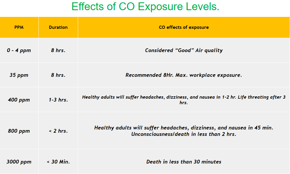
The following table in Fig. 2 shows the effects of carbon monoxide exposure levels in the air.
Who is at Risk from Carbon Monoxide Poisoning?
All people are at risk for carbon monoxide poisoning. The elderly and people with chronic heart disease or respiratory problems are generally more at risk than others. In the condition of carbon monoxide poisoning, the patient must be moved away from the CO source to fresh air immediately. In an emergency room, oxygen therapy is the main treatment for carbon monoxide poisoning.
Regulatory Measures for Workplace Safety
Recognizing the gravity of occupational carbon monoxide poisoning, regulatory measures are imperative to safeguard workers. These measures should encompass comprehensive awareness programs, stringent maintenance standards, and proper ventilation protocols in workplaces where CO exposure is a potential risk.
What are the Potential Long-term Effects of Carbon Monoxide Poisoning?
Carbon monoxide (CO) poisoning can have lasting and potentially severe long-term effects, especially if the exposure was significant or went untreated. Some of the potential long-term effects of carbon monoxide poisoning include:
- Neurological Symptoms: CO poisoning can cause lasting neurological issues, including memory problems, difficulty concentrating, and changes in behavior and mood. These cognitive deficits can persist for an extended period after the initial exposure.
- Psychiatric Symptoms: Individuals who have experienced CO poisoning may be at an increased risk of developing psychiatric symptoms such as depression, anxiety, and post-traumatic stress disorder (PTSD).
- Headaches: Chronic, recurring headaches can be a lingering symptom of CO poisoning. These headaches may persist long after the initial exposure.
- Fatigue: Many people who have survived CO poisoning report persistent fatigue and a general sense of weakness, which can interfere with daily functioning.
- Balance and Coordination Issues: Some individuals may experience difficulties with balance and coordination, which can affect mobility and daily activities.
- Visual and Auditory Disturbances: Vision problems, such as blurred or double vision, as well as hearing issues, can occur as a result of CO poisoning.
- Cardiovascular Effects: Long-term exposure to CO has been associated with an increased risk of heart problems, including an elevated risk of heart disease.
- Respiratory Problems: CO exposure can lead to respiratory issues, such as chronic coughing and shortness of breath, especially in individuals with preexisting lung conditions.
- Movement Disorders: In some cases, CO poisoning can result in movement disorders, including parkinsonism, chorea, and choreoathetosis.
- Peripheral Neuropathy: Peripheral neuropathy, which involves damage to the peripheral nerves, can lead to tingling, numbness, and weakness in the extremities.
Uncommon complications of carbon monoxide poisoning include well-defined neurological conditions such as:
- Parkinsonism, chorea, and choreoathetosis (which correlate with lesions of the putamen and globus pallidus seen on computed tomography and magnetic resonance imaging)
- cortical blindness
- mutism
- hemiplegia
- peripheral neuropathy.
Mechanisms of CO Toxicity
CO reduces oxygen delivery to tissues in several ways:
- It combines with hemoglobin to form carboxyhemoglobin (COHb), reducing the amount of hemoglobin available to carry oxygen (CO has 240 times the affinity of O2).
- The formation of COHb shifts the oxyhemoglobin dissociation curve to the left, impairing the liberation of oxygen to the cells.
- CO binds to myoglobin and cytochrome oxidases (particularly cytochrome a and cytochrome a3) and may impair their ability to utilize the oxygen they receive.
- Tissue oxygenation, particularly in vulnerable organs such as the brain, may be further impaired if poisoning is complicated by peripheral circulatory failure. Lipid peroxidation results.
How long does Carbon Monoxide Poisoning Last?
The duration and severity of carbon monoxide (CO) poisoning can vary significantly depending on several factors, including the level and duration of CO exposure, individual health, and promptness of treatment. CO poisoning can be categorized into three general phases:
- Acute Phase: This phase occurs shortly after exposure to high levels of carbon monoxide. Symptoms such as headaches, dizziness, nausea, and confusion can manifest within a few hours of exposure. In mild cases, these symptoms may resolve once the affected individual is removed from the CO source and exposed to fresh air. However, in more severe cases, symptoms can progress to loss of consciousness and death within hours.
- Intermediate Phase: In some cases, individuals who initially recover from acute symptoms may experience a delayed recurrence of symptoms, known as the intermediate phase. This can occur within hours to days after the initial exposure. Symptoms may reappear or worsen and can include neurological problems, cognitive deficits, and behavioral changes.
- Chronic Phase: Chronic or long-term effects of CO poisoning can persist for weeks to months after the initial exposure. These effects may include persistent neurological and cognitive symptoms, mood disturbances, and fatigue. Some individuals may continue to experience health problems for an extended period, while others may recover more quickly.
How to Avoid Carbon Monoxide Poisoning?
Avoiding carbon monoxide (CO) poisoning is essential for your safety and the well-being of those around you. Here are some important steps and precautions to help you prevent CO exposure:
- Install Carbon Monoxide Detectors
- Regularly Test and Maintain Detectors
- Proper Ventilation
- Minimize the Use of Gas-Powered Equipment
- Properly Maintain Equipment and Appliances
- Regular Inspections
- Educate all staff
- Stay Informed about CO safety.
Few more useful resources for you…
What is Engineering Process Safety?
Safety Rules during A Field Visit By A Design Engineer
An article on Crane safety during Construction
HAZOP (Hazard and Operability) Study: A brief introduction
An article on Excavation Hazards at Construction Sites
Hazardous Area- Theory, Classification and Equipment selection: A short presentation
An article on THE HAZARDS OF PRESSURE TESTING
About the Author: The author of part of this article is Mr. Amir Razmi, an International, dynamic, and multi-functional chemical engineer with more than 17 years of experience in engineering and EPC of oil and energy projects from pre-contract activities to execution, and closeout.