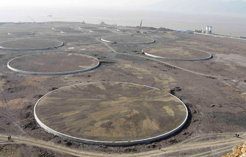
Used for Vertical storage tanks, Circular in shape having a larger diameter
Used where there are no anchorage requirements for the tank (as specified by the tank vendor)
Components of Tank Pad foundation:
Tank Pad body
Tank Pad Shoulder
Finishes
Tank foundation functions and requirements :
The functions of a tank foundation are:
To spread and transfer the load from the tank and its contents via the tank foundation body and shoulder to the subgrade so that the settlement remains within the allowable limits.
To provide a smooth surface with sufficient bearing capacity and stability for tank construction and operation
To channel rainwater away from the tank shell and tank bottom quickly
The requirements for the shoulder of the tank foundations are:
To provide sufficient lateral support to the tank foundation during construction, operation, and maintenance activities
To resist edge settlement beneath the tank shell
To resist erosion by wind and/or water
Design Parameters:
The tank foundation shall be designed to ensure that it is capable of:
absorbing subsoil deformations to ensure deformations in the tank base remain within limits
the possible unequal foundation pressures
Under certain circumstances, soil improvement under the tank foundation shall be considered in order to:
provide a foundation with sufficient strength
reduce large settlements
The minimum elevation of the tank foundation at the base of the tank shall be 0.60 m above the adjacent terrain.
Fig. 1: Example of Typical Tank Foundation
Drain pipes shall be placed around the circumference of the foundation in order to detect leakages (if any) and to prevent the build-up of pore pressure due to liquid accumulating in the tank pad.
Geo-textile membrane shall be installed under the surface finishing to the shoulder if there is a possibility of washout of fine materials
Stability analysis of the shoulder and tank foundation shall take into account the following aspects :
wind loads
earthquake loads
initial height above adjacent ground level
highest possible groundwater level
the angle of slope of the shoulder
geotechnical properties of the tank foundation materials and subsoil
load provided by the tank and its contents during hydrostatic testing, operation, and maintenance
Tank Foundation Shoulders:
The shoulder width shall be selected such that the stability of the foundation, shoulder, and subsoil is ensured. The minimum width of the tank foundation shoulder (S) depends on several aspects:
height of the tank (H)
the density of the product
the slope of the tank foundation edge
height of the tank foundation (T)
The shoulder shall have a gradient of 1:10. The slope to the shoulder shall not exceed a gradient of 1:1.5.
Materials:
Tank pad foundations are constructed with durable, granular materials, such as crushed rock, coarse sand, etc.
The tank foundation body shall be constructed from clean granular materials which meet the following requirements:
not crushable
low compressibility
high friction properties
low silt content
free draining
insensitive to weathering, chemical changes
easy to compact
not sensitive to liquefaction (especially when constructed in earthquake zones).
Well-compacted sand, especially coarse sand, meets the above requirements providing the chemical and mechanical stability of the minerals is guaranteed.
In order to prevent the capillary rise of the groundwater the upper 200 mm of the tank foundation shall comprise coarse sand.
Tank foundation finishes:
The purpose of the surface finishing layer under the tank is:
To act as a barrier to corrosion promoted by water or water vapor, together with chemicals that may be present in the tank foundation or subsoil
To promote a uniform distribution of stress from the tank bottom to the tank foundation
To allow thermal expansion of the tank bottom
The function of the surface finishes of the tank foundation shoulder is to protect the foundation from damage caused by weathering, erosion, and construction, operation, and maintenance activities.
The surface finish layer under the tank shall be a mixture of sand and bitumen.
The final levels of the placed and compacted surface finish under the tank edge between any two points 10 m apart around the periphery of the tank shall not be greater than +/- 6 mm.
The tank foundation shoulder may, like bund walls, be covered by a mixture of sand, bitumen, and cement or lime (i.e. a wet sand mix).
The surface finish to the shoulder shall have a gradient slope of 1 vertical in 10 horizontal from the underside of the annular plate of the tank, to avoid ingress of water under the tank.
During the construction of the tank foundation, necessary tests are performed on each 0.3m thick layer placed and compacted.
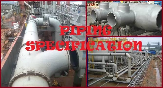
Piping Specifications | Piping Material Specification (PMS) | Piping Class
Piping Specification (pipe spec, in abbreviated form ) is the most important piping document for a project that is prepared during the design phase of any project. They provide all the basic guidelines that need to be followed while proceeding with the design of the project.
The Function of a Piping Specification
Piping Specifications are engineering documents, generated by design consultancies to cover additional requirements applicable to a specific product or application. Piping Specs provides specific/additional requirements for the materials, components, or services that are beyond the code and standard requirements and based on engineering experience and best practices of the design companies.
Types of Piping Specifications
In Piping Design Companies/Consultancies, more than twenty-five (25+) Specifications (most of the time they are referred to as pipe spec, in abbreviated form) are used that cover piping-related issues. There will be a “piping specification” for:
This partial list provides some of the specific piping specifications that are found on most projects in design companies.
How to Make a Pipe Material Specifications?
All Piping Material Class Specifications must have a front cover with a written section containing the following:
Document Title
Document Number along with Revision history
Name of Responsible person, checker, and approver along with creation date
Contents in Tabular or properly arranged format
Functional or Purpose Statement
General Notes
A list mentioning all the applicable Codes that apply to the materials added in the specification
A list specifying the Line Classes with data like Material, Commodity, Flange Rating, etc.
All individual Line Class sheets
All common drains, vents, and other miscellaneous details with the proper connection.
Header and Branch Connection Tables
All of this will then be issued as a single document with the title “Piping Material Specification” or PMS.
Basic Data Required for Piping Material Specification
Data Requirements for Pipe Material Specification
The piping material engineer will need the following information:
List of all commodities like feed, all products, all waste streams, all utilities, and all additives that are part of the project.
Complete chemistry of each commodity which includes Toxic classifications and reactions to changes in temperature.
Maximum sustained operating pressure and temperature of every commodity. Also, Any short-term or upset condition that may cause an increase or decrease in pressure or temperature.
Corrosion rate for different pipe materials when in touch with the above commodities.
Expected maximum and minimum pipe size (Nominal Bore) for the project.
The next importance is in knowing the Client’s preferences and or restrictions for materials, valves, flanges, or any other items.
Next, required to know the expected “Design Life” of the plant to determine the corrosion allowance for selecting the final pipe schedule.
Now to prepare the finished “ Piping Line Class” or “piping material specification”, The Engineer may create a word or excel document with the following headers:
Block indicating piping class details and revision status
A piping class is defined as an assembly of piping components that are suitable for a defined service and design limits within a piping system. The piping class or Pipe Class is an important document that specifies all the required components under a specific design limit. Typical components that are covered in a piping class are the type of pipe, material, schedule, corrosion allowance, flange ratings, branch types, valve types, valve trim material, gasket, and all the other components’ specific requirements.
Pipe class development mainly considers the Design and Operating Pressure, temperature, and corrosive environment. Different piping material specifications are segregated into separate “Piping Classes”. Pipe class is included in the line number to help engineers easily identify the MOC of each piping item.
What are the advantages of a Piping Class?
The generation of piping class provides multifold benefits to plant design engineers. Some of the advantages of designing and purchasing piping following piping classes are listed below:
A large reduction in piping system engineering and procurement effort due to internal design standardization.
Group-wide standardization of piping material and piping systems design;
Variety control which leads to reduced costs for stocking materials;
Integrity and Quality control in relation to applied standards;
Increased leverage for centralized purchasing;
Reduction of the risk associated with wrong material selection.
Differences between Piping Specification and Piping Class
Here’s a tabulation of the major differences between a piping class and a piping specification:
Aspect
Piping Class
Piping Specification
Definition
A piping class is a collection of related piping components, defined for a particular application or service.
A piping specification is a document that provides detailed information about the requirements and standards for piping materials and components.
Purpose
A piping class is used to group and categorize piping components for ease of design, procurement, and installation.
A piping specification is used to define the technical and material requirements for the components used in piping systems.
Scope
A piping class typically includes a set of materials, components, and accessories organized for a specific type of service or environment.
A piping spec. focuses on the technical details, including material grades, dimensions, and pressure ratings for piping components.
Components Included
Includes pipes, fittings, flanges, valves, and supports, often categorized by service or fluid type.
Includes detailed descriptions of pipe materials, wall thicknesses, pressure ratings, and other technical specifications.
Detail Level
Generally broader, categorizing components and materials based on service requirements.
More detailed, providing specific standards and requirements for each component.
Usage
Used by designers and engineers to select and use components based on the type of system or service.
Used by engineers and procurement teams to ensure all components meet the required standards and specifications.
Documentation
May include tables, diagrams, and descriptions to categorize components.
Usually a formal document or set of documents detailing technical standards, material requirements, and testing procedures.
Customization
Can be customized based on project needs or industry standards, reflecting the specific requirements of a project.
Highly specific, based on industry codes, standards, and project requirements, with less variation.
Examples
A class for high-temperature steam service, including appropriate materials and components for that service.
A specification detailing the requirements for carbon steel pipes, including allowable pressure ratings and material grades.
Table 1: Piping Class vs Piping Specification
Both piping classes and piping specifications are critical for designing and maintaining effective and reliable piping systems, but they serve different purposes and provide different types of information.
Who is responsible for generating Piping Material Specification?
Piping material engineers prepare the piping material specification and piping classes by discussing with process engineers. Most of the data required for producing a pipe material class is received from the process team.
About the Author: This article has been prepared by Dr. Javier Blasco Alberto, Associate Professor, School of Engineering and Architecture, University of Zaragoza. He also collaborates actively with InIPED.
An oil mist lubrication system is a widely used bearing lubrication. A centralized lubrication system generates and automatically delivers the lubricant to machinery bearings to keep them lubricated for making moving parts reliable. The fine mixture of oil and air that is generated is called oil mist. Oil-mist lubrication ensures a high standard of lubrication as and when required and prevents the ingress of contaminants to the bearing housing.
Various Types of Lubrication
Splash Lubrication
Grease Lubrication
Forced Lubrication
Solid Lubrication
Mist Lubrication
Oil Mist System is a means of generating and transporting a finely dispersed oil mist from a central location to individual bearing housings.
The oil mist system uses compressed air to atomize oil into micron-size particles which can be effectively moved to lubrication points up to 600 feet (180 meters) through Pipes & Tubes
One Oil Mist system can provide lubrication to 60 pumps and their drivers with approximate oil consumption of one gallon (3.8L) of oil per 24 hours.
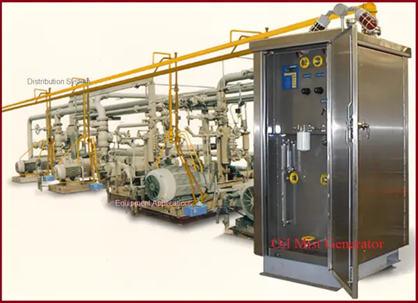
Typical Oil Mist System
Refer to Fig. 1 which shows a typical oil mist lubrication system used for industrial applications.
Fig. 1: Typical Oil Mist System
Types of Oil Mist Lubrication Systems
The oil mist lubrication system can be categorized into the following types.
Open Loop System (Fig. 2)
Closed-Loop System (Fig. 2)
Dry Sump (Pure Mist-Fig. 3)
Wet Sump (Purge Mist-Fig. 3)
Fig. 2: Open and Closed Loop Mist Lubrication System
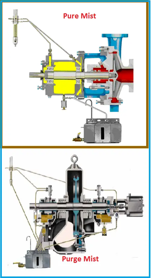
Pure & Purge Mist Lubrication
Pure Mist Lubrication System-
The bearing is lubricated by oil mist, not oil.
Bearings can run 10-15 degC cooler with pure mist as compared to sump lubrication.
The bearing housing is pressurized by continuous oil mist flow, then external contaminants (dust, moisture…) are excluded.
Centrally controlled hence attention to oil level is not required individually.
Purge Mist Lubrication System-
The bearing is lubricated by oil, not oil mist.
The bearing housing is pressurized by continuous oil mist flow, then external contaminants (dust, moisture…) are excluded.
Here mist purges the bearing housing and provides partial fresh Makeup oil.
Oil levels must be checked and maintained for each piece of equipment.
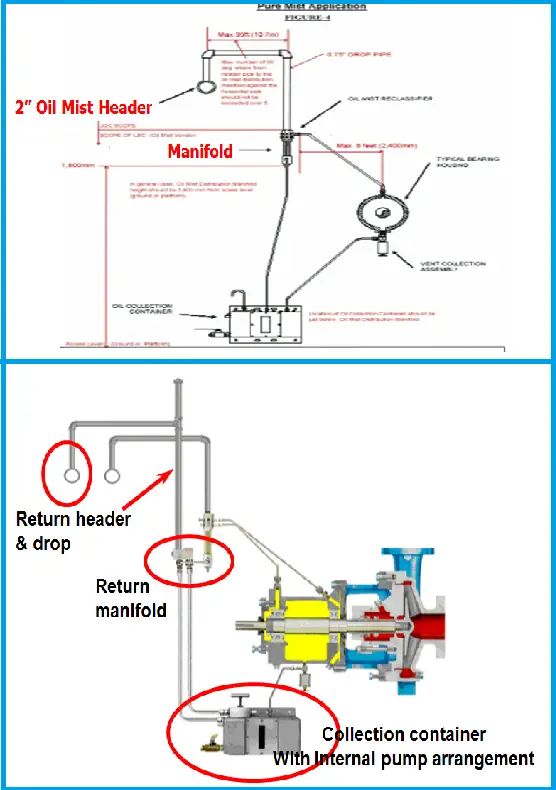
Fig. 3 below shows typical pure and purge mist lubrication systems.
Fig. 3: Pure and Purge Mist Lubrication
Components of Oil-Mist Lubrication Systems
The major components of the oil-mist lubrication system are listed below:
Oil mist generator- the heart of the oil mist lubrication system, compressed air is passed through a venturi or vortex to produce the oil-mist mixture.
Oil mist cabinet-Stainless steel cabinet.
Reclassifiers- Controls the mist flow to applicable points. Bearing type, shaft speed, and diameter dictate the sizing of reclassifiers.
Air- Clean and Dry air free from toxic, corrosive, and flammable elements.
Air Filter at the air inlet.
Air regulator to control supply air pressure
Air Pre-Heater-For cold climates to maintain the air temperature
While selecting the oil for an oil-mist lubrication system, the following factors need to be considered:
Oil Viscosity at the operating temperature
Pour point
Surface tension
Solidification tendency of the oil at low ambient temperatures
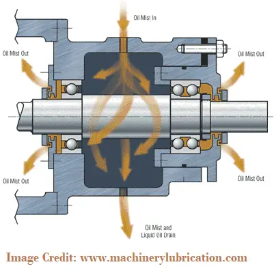
How does oil mist Lubrication lubricates the bearing?
The following figure (Fig. 4) shows the working of the oil-mist lubrication system to enhance bearing life.
Fig. 4: Working of Oil-Mist Lubrication System
Mist Lubrication Suitability
Rolling element and sliding contact bearings can be lubricated with Oil Mist either Pure or Purge type.
Oil mist is used to lubricate rolling element bearings of all types. Ball & Roller bearings are generally applied with Pure Mist Lubrication.
When sliding contact bearings are used, oil mist alone does not provide complete lubrication & hence, an oil level is maintained in the bearing housing and is called Purge Mist Lubrication.
Advantages of Oil Mist Lubrication System
Oil mist lubrication system offers various advantages over the other lubrication systems as listed below
Prevent the dust/moisture ingress into bearing housing, due to the pressurized system
Increased Bearing Life
Lower friction and thus reduced bearing temperatures
Reduced maintenance, reduced handling, and spillage.
As the bearings operate in a thin film of oil, so less power is required.
Reduced Oil consumption (40% less & 50% of it can be recovered)
More environmentally friendly than the conventional lubrication system.
As the oil on the bearings is always new, it provides better lubricant properties.
In technical papers released by end-users and bearing manufacturers, as well as in university research, bearings lubricated with oil mist have a longer life than bearings lubricated with oil sump or grease. Users report from a 50% to 90% reduction in lubrication-related bearing failures.
Finally, it is economic to use.
Disadvantages of Oil Mist Lubrication System
Even though mist lubrication systems have various advantages and reduce maintenance and operating problems, still there are a few disadvantages of this system such as
Relay on Instrument Air System
LSC is the single vendor of the Oil Mist System for Hydrocarbon Processing Industries
An oil mist system is almost trouble-free but it cannot be installed and forgotten. Systems should be checked daily for correct air and oil temperature, oil level, and mist header pressure along with other weekly and monthly maintenance programs.
The oil-mist lubrication system involves environmental hazards. OSHA requirement states that a person shall not be exposed to more than five milligrams of oil per cubic meter of air in an eight-hour period.
The performance of the oil mist lubrication system is sensitive to temperature.
Corrosion can be defined as the deterioration of materials under the influence of an environment. Without exception, the corrosion of metals and alloys (a majority of materials used in industry) in aqueous environments (the most often encountered environment) is an electrochemical reaction.
Factors affecting Corrosion
Corrosion behavior depends on the following factors:
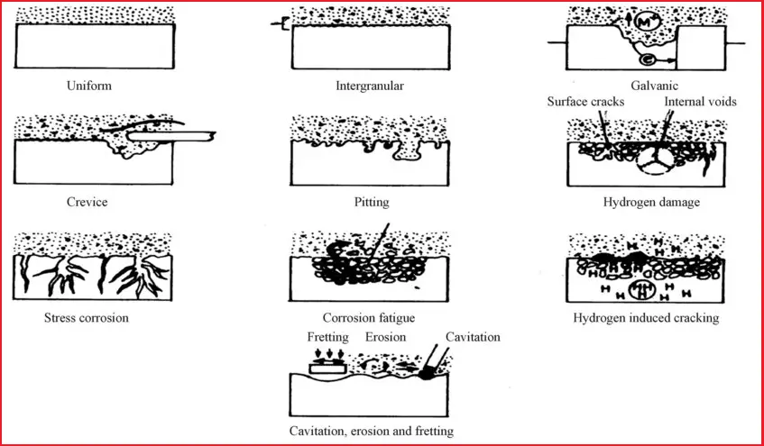
Fig. 1 shows the normal types of Corrosion that are prevalent in the Oil and Gas Industry.
Fig. 1: Types of Corrosion in the Oil and Gas industry
Uniform Corrosion
Though uniform corrosion is an idealized form of corrosion and because of less damage than the other forms of corrosion, it is more appropriate to understand this form of corrosion. This leads to uniform thinning of the structures.
Units of Corrosion | Corrosion Measurement
The corrosion attack is measured in terms of penetration. Corrosion is expressed in the units mpy (mills per year) or mm per year. This can be determined by any gravimetric method.
When dissimilar metals or alloys differing in their galvanic or corrosion potential are employed and if they are electrically shorted they induce this type of corrosion. The corrosion rate of the alloy with lower corrosion potential will be accelerated by that of higher corrosion potential.
Identification of Galvanic Corrosion
The active metal is corroded
Grooving of the interface
Noble metal deposits from the stream
Graphite lining or bricks
Prevention of Galvanic Corrosion
Provide electrical insulation between the metal
Choose alloys closer to the galvanic series
Provide design in structure so as to make anodic to cathodic ratio extremely large.
Coat both anode and cathodic areas. Otherwise, coat only the cathode.
Protect the corroding metal with a sacrificial anode, which is anodic to the corroding metal.
Crevice Corrosion
Accelerated corrosion occurs if differential aeration exists due to crevice, metal joining (lap joints, flanges, etc.), or any deposits. Interestingly the location starving for oxygen is forced to become anodic and the region having free access to oxygen becomes the cathode.
Identification of Crevice Corrosion
Rivets, flanges, and lap joints are attacked internally.
Deposits such as corrosion products, organic deposits, growth of organisms, etc. cause corrosion.
Improper drainage of vessels and pipelines causes an accelerated attack.
Prevention of Crevice Corrosion
Avoid riveting, go in for welding
Design for proper drainage
For stainless steels, high Mo content (316, 317, and Hastelloy) reduces crevice corrosion
Remove the deposits
Use solid non-absorbent gaskets
Pitting Corrosion
Alloys in presence of certain ions (such as halides) are prone to pitting. The rate of penetration within the pit can be as high as one million times as compared to the surroundings.
Identification of Pitting Corrosion
Pinholes
Normally grow in the direction of gravity
The alloy environment combination is likely to promote pitting
Pitting has taken place along the inclusion
Prevention of Pitting Corrosion
Eliminate the specific ions responsible for pitting (say halides in the case of SS)
Choose an alloy resistant to pitting. In stainless steels, high Mo promotes resistance (haste alloys, duplex stainless steels)
Mild steels serve better in a chloride environment than SS if a certain amount of uniform corrosion is tolerated. Monel has more resistance in this environment.
Selective Leaching (De-Zincification)
When noble and active elements form an alloy it results in the selective removal of the latter. As a consequence, the alloy loses its strength and fails prematurely. Cu-Zn alloys are well known wherein dezincification occurs if Zn content exceeds 15 wl. Similarly, there is de-nickelification, de-siliconation, de-cobaltification.
Identification of Leaching
They give rise to plug and layered types of attack.
Change in color (from yellow to brown in the cases of brasses)
X-ray diffraction can sometimes reveal the selective removal of one element
There can be a change in density in some cases.
Prevention of Leaching
Addition of any one of the elements namely Sn, As, Sb and P
Al addition reduces overall corrosion and to some extent dezincification.
Intergranular Corrosion
This type of corrosion occurs as a result of a selective attack of the grain boundaries when either the grain boundary becomes highly active or phases prone to selective attack are formed. Stainless steels, which are normally resistant to intergranular attack, when subjected to a heat treatment between 400-900 C become sensitive to intergranular corrosion (IGC). This range can vary depending on the composition of the alloy. This treatment is called sensitization treatment and the alloy is said to be sensitized. This is mainly due to the formation of Cr23C6 and the consequent grain boundary depletion. Welding, a common practice in fabrication causes such an IGC attack.
Identification of Intergranular Corrosion
The attack of the alloy away from the weldment is called a heat-affected zone.
Clear ditch type of attack along the grain boundary and consequent weakening seen at higher magnification.
Prevention of Intergranular Corrosion
Choose low-carbon and extra-low-carbon stainless steels (such SS are 3041,3161,3171)
Choose Ti or Ta and Nb containing alloys (321,347)
Provide a solutions treatment to redissolve the carbides (1050 °C, 30 m)
Erosion Corrosion
When there is a relative movement of the corrosive environment with respect to the alloy it can lead to erosion-corrosion. Pipelines and heat exchangers are subjected to such a kind of failure.
Identification of Erosion Corrosion
Attack at the bends in pipelines
Grooves in the direction of liquid flow.
Prevention of Erosion Corrosion
Reduce the velocity of the medium
Choose hard materials
Avoid sharp turns
Provide hard coatings.
Cavitation Damage
Some variation in erosion-corrosion is cavitation damage. Here there is damage due to bubble formation and collapse when there is hydrodynamic variation in pressure difference along the line. At low-pressure water/liquid vaporizes. When the same is subjected to higher pressure bubble forms and subsequently implodes. This leads to plastic deformation and the formation of cavities as brought out in.
Fretting Damage
Moving/vibrating interfaces under load cause damage akin to wear called fretting damage. Here the relative movement is relatively small in angstroms. A typical failed surface under this process is brought out.
Stress Corrosion Cracking (SCC)
When there is a conjoint action of stress and environment. Stress corrosion cracking occurs (SCC). However, SCC is specific to an environment. The alloys are susceptible to SCC only when specific ions are present akin to pitting corrosion. In addition, the alloys fail only if the stress exceeds a threshold level below which they are safe.
Identification of SCC
SCC in austenitic stainless steel is predominantly trans-granular in nature.
Failure occurs by brittle mode.
Ions promoting the SCC of that particular alloy must be present. Say Cl and O2 for austenitic SS and ammoniacal solution for Cu base alloys.
If the alloy is sensitized it can promote an intergranular mode of cracking.
Prevention of SCC
Select the alloy that is not susceptible to the environment.
In the case of SS, control either Cr or O2 one can keep either one of the low.
Apply load lower than the threshold stress.
Provide compressive stresses by sandblasting or shot blasting.
Avoid stress concentration.
Corrosion rates for a few materials
The following table provides some typical atmospheric corrosion rate values in mils/yr for some common materials
Atmospheric Corrosion rates (mils/yr)
Material
Rural
Industrial
Marine
Severe
A 242 type 1
0.05-0.16
0.06-0.60
0.17-0.37
0.83-2.20
A 514 type B
0.06-0.20
0.06-0.40
0.20-0.70
0.10-0.50
A 514 type F
–
0.34-1.60
0.30-1.00
0.53-0.70
A 517 type B
0.06-0.26
0.06-1.60
0.19-1.00
0.11-0.70
A 588 Gr A
0.10-0.24
0.14-0.47
0.25-0.80
3.05-4.1
Structural Steel
0.15-0.29
0.17-0.73
0.37-0.90
7.20-9.0
Stainless Steel
Only Pitting, No general corrosion
Table: Typical Atmospheric Corrosion rates for some Materials (ASM Handbook of Corrosion data)
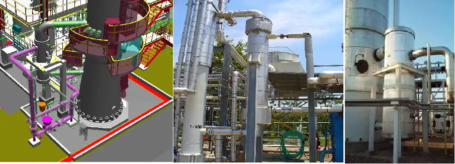
Vertical Reboilers play a significant role in the Process industry. Reboilers are a type of Heat exchanger that is used for heating the bottom fluid of industrial Distillation columns. Normally heat from steam (or any other high-temperature fluid) is utilized to boil the liquid from the bottom of a Distillation Column. Normally this heating effect generates vapor which is then returned back to the Column at a higher elevation to drive the distillation separation.
The piping arrangement between the distillation column and reboiler for this action is normally very stiff and requires careful Analysis to keep the column and Reboiler nozzle loadings within an acceptable limit. The following article will provide the Stress analysis methodology of a vertical Reboiler connected piping system using the software tool Caesar II, developed by Coade Inc.
Applicable codes and standards for Reboiler Piping Stress Analysis
ASME B 31.3-Process Piping,
ASME Section VIII-Pressure Vessel design (Normally distillation columns and reboilers are manufactured based on these codes),
Column and Reboiler allowable nozzle Loads (Should be taken from Equipment Vendor in case no standard Project-specific load is not available)
Temperature Profile for Modeling the Rebolier and Column
Column Temperature
In the absence of project-specific guidelines, the Operating/ Design temperature of the Column shall be considered the same as the average operating/design temperature of the column outlet piping attached to each draw-off nozzle
Reboiler Temperature
The Reboiler modeling uses the following information in the absence of project-specific guidelines:
Tube side Inlet Temperature = bottom (outlet) Piping temperature of the tower.
The temperature of the tube = average temperature between tube inlet and outlet piping.
Tube side outlet temperature = temperature of the tower inlet piping.
If the temperature of the Column inlet piping (channel outlet) is not known, consider the reboiler tube outlet temperature as mentioned in the vendor drawing or confirm from the process engineer.
Shell side temperature = average of the Shell inlet (Normally Steam) and outlet piping (Normally Condensate).
Modeling of the Reboiler with an Expansion joint in Caesar II
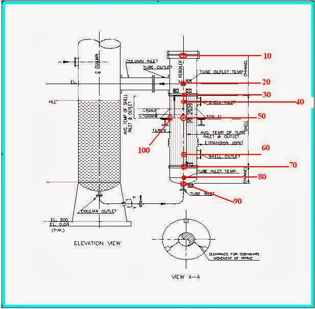
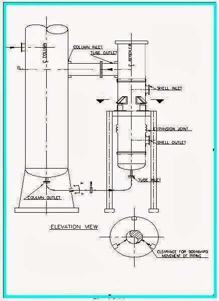
Initially model the reboiler as a rigid body following the below-mentioned steps. Refer attached drawing (Fig. 1) as a reference:
1. Model nodes 10-20 and 20-30 with tube outlet temperature and pressure considering channel material, diameter, thickness, length, and fluid density (Also include insulation thickness and density if any) from Rebolier General Arrangement (Henceforth called GA) drawing.
2. Model nodes 30-40, 40-50, and 60-70 with shell average temperature and shell design pressure considering shell material and dimensions as mentioned in reboiler GA.
3. Model element 30-70 with Channelside average temperature and design pressure taking tube material, shell diameter, and thickness from GA drawing.
4. Model 70-80 and 80-90 with tube inlet temperature and pressure considering channel material, diameter, thickness, and length.
Fig. 1: Reboiler piping schematic diagram for modeling in Caesar II
5. Model elements 50-100 with shell-side properties and model the support restraint at node 100. Similarly model all other support elements as required from the GA drawing (check 2 lugs, 3 lugs or 4 lugs supported system).
6. Now make the elements 10-20, 20-30, and 70-80 as flexible (i.e, non-rigid)
7. Check the total operating weight of the reboiler from GA (if operating weight is not available assume 70% of water-filled weight) and the weight already considered in elements mentioned in step no 6 (considering fluid and insulation; you can do it easily by clicking the single run button in caesar II). Provide the remaining balance weight in rigid element 30-70 (tube weight). Recheck once again by clicking the single run button to ensure the actual weight in the caesar model matches the weight provided in GA.
In case there is no expansion joint in the shell, model element 30-70 with shell-side average temperature. Rest all other parameters will remain the same.
As you are planning for reboiler piping I am sure you know the modeling of the column and attached piping. So I am not describing it. So model the column and attached piping to make a complete system as shown in the attached figure (Fig. 1).
Supporting Arrangement for Vertical Reboiler Piping
Reboilers may be supported by the column or by making an independent structure. In both of cases, there is a possibility to support the reboiler lugs directly on the structure or there may be a requirement for spring hangers (bottom mounted). Sometimes Slot holes and PTFE/graphite sliding plates are required to reduce frictional effects. So this information needs to be informed to the equipment vendor. Location of the lugs to be fixed in such a manner with respect to nozzles, bellows, and other accessories to avoid fouling, etc. If the reboiler is supported on spring supports (See attached figure Fig. 2) then the following points need to be considered:
Cold/Hot Load Conditions should be the same for all the springs
Spring should be designed keeping in consideration the empty weight of the reboiler in case of standby and steam out condition.
Slotted Holes are not required on the lug of reboiler in case of spring support
Fig. 2 : Supporting Arrangement of Vertical Reboiler Piping using Spring hangers
Mirror polished SS plates/PTFE plates if required are to be provided by the vendor
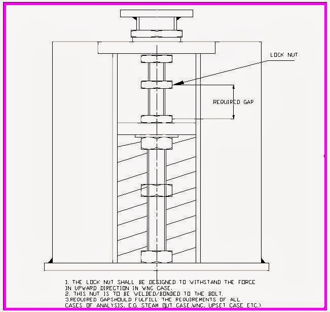
If the loads on nozzle are quite large because of the back force due to spring in WNC Case, the Lock Nut (Refer above figure) can be provided on spring to act as the limit stop.
The required gap shall be input in Caesar as a gap on restraint applied at spring in (negative Y) Direction.
The pipe stress Engineer has to provide details of the Lock Nut (See the figure attached below, Fig 3) and the loads on the nut in the Spring Datasheet.
Fig. 3: Locknut arrangement for Reboiler Piping Supporting
Load cases for Reboiler Piping analysis
Load cases are to be prepared based on operation possibility. So one must consult with the process engineer to know all the possible load cases. Normal possibilities are mentioned below:
1. Operating temperature load cases (W+P1+T1)
2. Design temperature load cases (W+P1+T2)
3. Steam out temperature load cases (W+P1+T3)
4. Upset Condition load cases (W+P1+T4): This condition may arise if the fluid is flowing in one part of the reboiler and no fluid is flowing through the other. Normally during start-up, these types of cases may appear. Sometimes it may happen that you have to first heat the reboiler shell before you can start the flow of process fluid through the tubes. Consultation must be done with the process engineer while creating all such load cases.
5. Sustained load cases (W+P1)
6. Prepare all occasional and expansion load cases as per normal project procedures. It is sometimes required that two or three reboilers of similar type are connected to the same column. In this case, some reboiler may be in standby condition. So that situation is also required to be interpreted while making load cases. So additional load cases need to be added accordingly.
Few Important Notes related to Re-boiler Piping Stress Analysis
Reboiler column circuits being one of the most critical systems from a stress analysis point of view one should take extreme care while analyzing such systems. The following notes will help the stress engineer to take an engineering judgment:
1)All of the junctions between the shell & nozzle can be considered as reinforced after confirmation from the Mechanical Department
2)If nozzle loads exceed the allowable, loads should be forwarded to mechanical for further evaluation. Alternatively, the stress engineer has to perform WRC or FEA to qualify the nozzle loads. It is better to forward the WRC/FEA output results to Mechanical for their review.
3)Nozzle loads should be checked thoroughly with the spring setting when the reboiler is on standby during steam out.
4)Flange leakage evaluation should be performed as per client requirement and the rating of flanges should be changed if required, and the same information should be forwarded to the Mechanical and Process Team.
5)Initially, the Nozzle loads are to be forwarded to mechanical as three times the project-specific pressure vessel loads in Caesar to take care of the upset conditions.
6) The requirement of Spring supports, PTFE/SS plates, Slot holes, Locknut arrangement, etc. is to be marked in the Engineering drawing for incorporation into the final vendor drawing.
7) Location of lug to be fixed in such a manner with respect to nozzles, bellows, and other accessories to avoid fouling, etc.
8) Fouling of the Reboiler Nozzle (Shell Outlet) with structure should be checked.
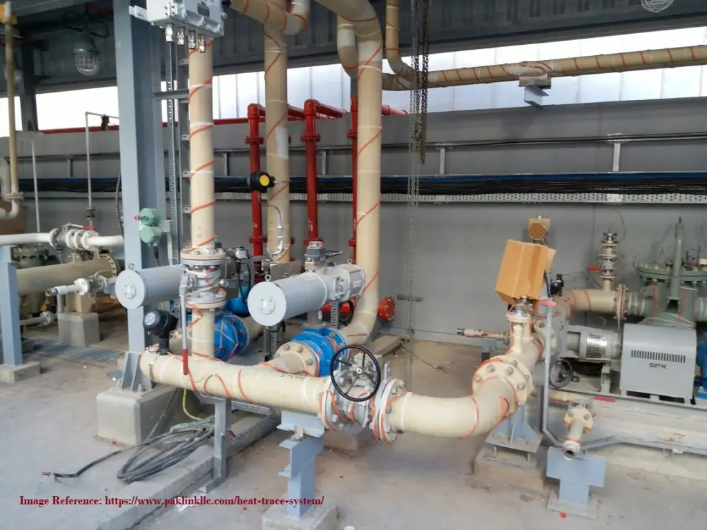
Pipe Heat Tracing is a generalized term relating to the application of radiant heat input to piping systems from tubing attached to the outside of the pipe. Heat tracing is a process requirement. Pipes carrying higher fluid temperatures than the ambient temperature will lose temperature to the surrounding. Insulation is a way to reduce this loss. But insulation is not 100% foolproof. So to make up for that heat loss, small-bore steam pipes or electrical wires (known as heat tracers) are attached to the parent pipe. This system is called the heat tracing of piping.
Purpose of Heat Tracing
Heat tracing serves various other purposes as listed below:
Maintaining the required temperature for the process fluid.
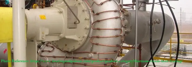
In Steam tracing (Fig. 1) of piping, steam is circulated through tubes that run alongside the pipes to keep the process fluid at the desired temperature. Other fluids like organics, glycols, etc can be used as tracing fluid in heat tracing system design. However, there are various advantages of using steam as heat tracing fluid as mentioned below:
The cost of steam generation is less as compared to other fluids. So steam tracing is economical.
The maintenance cost is also low. Once, the steam tracing network is installed, less maintenance costs will be involved.
Steam tracing of piping is highly energy efficient.
Pipe Steam tracing heats up the process fluid quickly.
No pumping is required for steam.
Temperature control in steam tracing is high.
Fig. 1: Steam Tracing Example
Electrical tracing
On the other hand, in electric tracing (Fig. 2) of the piping system, an electrical heating element transfers heat into the process fluid while running in physical contact along the pipe length. Heat is normally generated in an electrically resistive element. However, other effects like impedance, induction, skin conduction, etc can be utilized in electrical tracing. Electrical heat tracing is also known as cable heat tracing.
Fig. 2: Electric Tracing
Pipe Heat Tracing Cable
Appropriate heat tracing cable for electrical tracing is determined based on the following parameters:
Three types of pipe heat tracing cables are used for industrial electrical tracing systems. They are:
Self-regulating polymer jacketed cables: These heat trace cables are suitable for temperatures up to 200°C and circuit lengths of up to 750 feet.
Mineral insulated heat trace cables: Such heat tracing cables are used for a temperature of up to 650°C and circuit lengths of up to 3,300 feet.
Skin effect heating system cables: For moderate temperature ranges and much longer heating circuits, skin effect heat trace cables are used. They can be used up to 82,000 feet (25 km) in length and their rated temperature is up to 250°C.
Controlling heat tracing temperature for electrical tracing is very important. Various control panels are used for heat tracing temperature control. The heat tracing system shall be suitable for operation on 240V + 5%, 50 Hz, single-phase AC supply. The Power supply to the heater tapes/heat tracing cables shall be from local distribution panels (LDPs) located in the field at strategic locations /load centers to be decided by the contractor. However, the main Power Distribution Panel shall be located in Switchgear Room in a safe area.
Piping Heat Tracing tapes / Heating Tapes
Heat tracing cables are also known as heat tracing tapes. Industrial heat tracing tapes or heating tapes should possess the following characteristics:
Heat tracing tapes should easily wrap around the pipe or equipment.
Heating tapes should provide intimate contact with the pipe material for higher efficiency of heat transfer.
Heat tracing tapes should be fast in heating up.
Heating Tapes should be able to withstand higher required temperatures.
Heat tracing tapes or heat tracing cables must be durable and long-lasting
Additionally, the heating tapes should possess the following features:
To prevent damage during over-lapping, the heating tapes shall have a burn-out-proof feature.
The heating tapes shall be suitable for use in the area defined in the process datasheets. Corrosion-resistant metallic braid must be provided for safe and hazardous area applications.
In hazardous area applications, the surface temperature of the heating tapes shall not exceed 200 deg. C.
For valves, flanges, pipe supports, and similar heat sinks, an extra heater tape length shall be provided. The heater tapes to be installed should consider easy maintenance or removal of the valve, and pipe support.
Heat tape surfaces must be cleaned before the installation of heater tapes on pipes and other equipment.
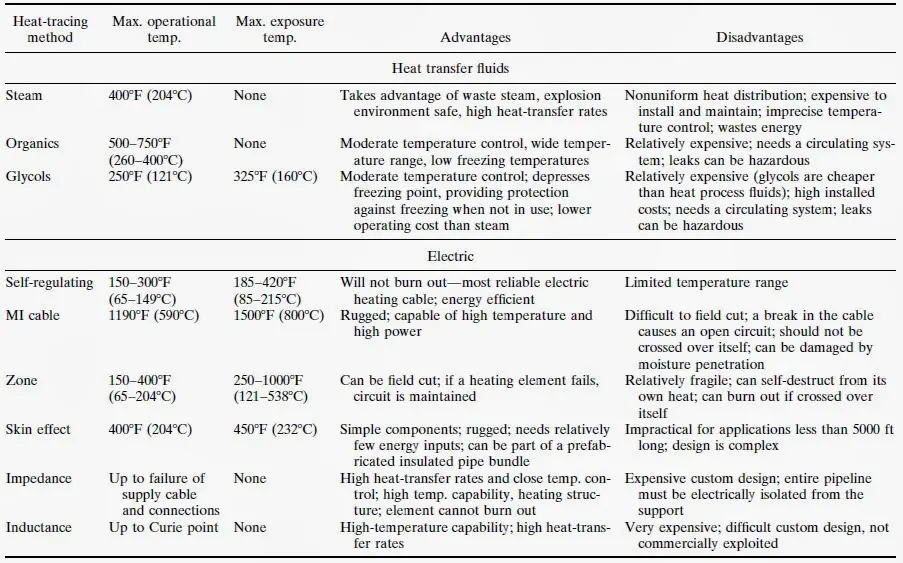
Advantages and Disadvantages of Piping Heat Tracing using Fluids or Electricity
The following figure shows the principal features of different types of heat tracing methods.
Fig. 3: Steam Tracing vs Electrical tracing
When Heat tracing is used to ensure that the system functions from a process standpoint regardless of climate conditions it is known as Process Control Tracing
Again when Heat tracing is used to prevent freeze-up due to climatic conditions only it is known as Winterization Tracing.
Heat tracing Design Steps
The following steps are followed for designing a pipe heat tracing system:
Calculation of heat loss from the pipe or equipment.
Adjust the heat loss for the insulation system.
Correct that heat loss considering wind speed and additional safety factor (margin).
So this calculated value will be used as input for heat tracing system design. The heat tracing system should add at least that much heat to the piping system to maintain the required heat (temperature) in the process fluid.
General Requirements for Piping Heat Tracing
General rules for Steam Tracing
Steam tracing supply lines shall be taken from the top of the supply header to assure dry-quality steam.
Identify the locations for steam tracing supply manifolds and condensate manifolds early in design to reserve space in plant layout. This applies to non-steam supply and returns manifolds (hot oil, glycol, etc.).
Allow for an increase in insulation sizing to allow for tracers.
Instrument Application for heat tracing
In-line instruments can also be required to be heat traced as process condition dictates. In that case, Piping needs to provide steam supply and condensate collection manifolds for all other instruments. The break between Piping Traced Instruments and Control Systems traced instruments will match the drawing break between the two departments.
Heat Tracing System Description
Using various media such as steam, hot water, glycol, or hot oil heat tracing is installed to protect the piping, equipment, and instruments against temperatures that would cause congealing or freezing of the process fluids, interfere with operation, or cause damage to the equipment.
Heat Tracing Design Requirements
The daily average low temperature of the coldest month shall be used to select the low ambient design temperature that then determines the degree of winterizing protection required.
No winterizing is required for water service except where a sustained temperature below minus 1 degree C is often recorded for 24 hours or longer.
Compressors, blowers, and other mechanical equipment shall be specified for operation at low ambient design temperatures.
Heat Conservation while Heat tracing
Where feasible, insulation shall be used for heat conservation. Heat tracing, plus insulation, is the alternative method for heat conservation.
Heat transfer cement may be utilized when a process line requires a high heat input and common methods of heat tracing are inadequate.
Steam jacketing is utilized in specific cases where steam tracing with heat transfer cement is inadequate.
Electric tracing is utilized when precise temperature control is required or where steam tracing is not practical. The thermostat setting for electric tracing should not be higher than the fluid operating temperature.
Methods for Winterization
Winterizing by circulation shall be provided where a sufficient power source is available to keep the fluid circulating.
Utility water and utility airlines in intermittent service shall be winterized by draining.
Winterizing by steam tracing is the preferred method when winterizing by circulation and draining is impracticable.
Winterizing by electric tracing is utilized when precise temperature control is required or where steam tracing is not practical. The thermostat setting for electric tracing should not be higher than the fluid operating temperature.
The minimum tracing steam pressure shall be 1 Bar; the maximum required is 10.3 Bar. At minimum pressure, condensate shall be routed to the plant sewer system. If condensate is collected, the minimum usable pressure shall be 1.7 Bar.
Heat Tracer Description
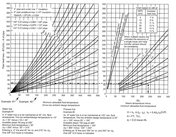
Pipe Tracer Size and Length
Required tracer size shall be determined by piping heat loss and tracer steam pressure found in the Heat Loss Chart (Fig. 1)
The minimum tracer size shall be 3/8 of an inch OD tubing; the maximum size shall be 1 inch OD tubing. For the economy, where Heat Loss Chart indicates the requirements for multiple tracers, a single tracer with heat transfer cement shall be considered.
When using heat transfer cement, tracers of 3/8 of an inch and 1/2 of an inch OD tubing are recommended. If more tracer area is required, multiple tracers of 3/8 of an inch and 1/2 of an inch shall be used.
Maximum tracer length shall be based on tracer size and steam pressure as follows:
Steam pressure 1 Bar through 1.7 Bar
60m for 3/8 of an inch and 1/2 of an inch tracers
100m for 3/4 of an inch and 1-inch tracers
Steam pressure 3.5 Bar through 13.8 Bar
60m for 3/8 of an inch and 1/2 of an inch tracers
120m for 3/4 of an inch and 1-inch tracers
Tracer lengths for Heat tracing with heat transfer cement shall be based on the recommendation of the manufacturer.
For stainless steel lines, the tracer material shall be low-carbon steel. Stainless steel instrument leads shall be traced with copper tubing.
Each tracer shall have its own trap. Tracer traps shall discharge to the sewer. If condensate must be collected, the minimum usable pressure is 1.7 Bar.
Compression-type fittings shall be installed outside of the insulation OD.
Socket-type fittings may be installed inside the insulation.
The steam tracers shall be pressure tested before the insulation is applied. Under emergency conditions, the insulation may be applied but the fittings shall be left exposed until the testing is complete.
Heat Tracer Pocket Depth
Pocket depth is the distance the tracer rises in the direction of flow from a low point to a high point. The total pocket depth is the sum of all risers of the tracer.
The maximum tracer total pocket depth shall be equal to 40 percent of tracing steam gage pressure expressed in meters.
Example: Tracing steam 10.3 bar 30 m x 0.40 = 12 m feet total pocket depth
Tubing used for steam tracing/heat tracing
Steam tracing tubing materials shall be in accordance with material specifications.
Tracers shall be OD tubing. Soft annealed copper tubing shall be used where the temperature of the product line or tracing steam does not exceed 204 °C. Above this temperature, dead-soft annealed hydraulic quality, low carbon, seamless steel tubing shall be used where the temperature of the product line or tracing steam does not exceed 399 °C.
For aluminum pipelines, carbon steel tracer material shall not be used.
For aluminum pipelines and all lines above 399 °C, the tracer material shall be stainless steel.
For conditions where the tracer could overheat lines containing acid, caustic, amine, phenolic water, or other chemicals, insulation spacer blocks shall be installed between the tracer and the pipe.