The term SIF (Stress Intensification Factor) is too confusing for many piping engineers. That’s why the following article is taken to explain the bend SIFs in simple language. Every piping Engineer who possesses a little basic of the Piping Stress Analysis theory must be aware of the term SIF or Stress Intensification Factor.
The term SIF indicates a multiplier of Bending and Torsional stresses. This Intensifier acts locally on a piping Component ( tees, elbows, bends, Olets, etc.) and Its value depends on component geometry. The minimum value of the SIF is 1.0. It is widely used by piping stress engineers in places where the actual stress calculation is quite difficult due to its difficult geometry (Varying thickness, cross-section, curvature, etc.) as, unlike straight Pipes, the simple Beam theory is not applicable. So in this situation, it is required to assume additional stresses by suitably incorporating an SIF. The following article will provide an example of SIF calculation of piping elbow or piping bends following process piping code ASME B31.3.
Fig.1: In-Plane, Out-Plane Concept as per Code
Stress Intensification Factor for a Piping Bend/Elbow
In layman’s language, the SIF of a bend or elbow can be defined as the ratio of bending stress of an elbow to that of a straight pipe of the same diameter and thickness when subjected to the same bending moment. Whenever the same bending moment is applied to a bend because of ovalization the bending stress of the elbow will be much higher than that of a straight pipe. That is why the SIF value will always be greater than or equal to 1.0 (for straight pipe).
The process piping code ASME B31J (Appendix D of ASME B31.3 till edition 2018 of ASME B31.3) provides a simple formula to calculate the SIF of a bend or elbow. As per that code
SIFin-plane = 0.9 / h(2/3)
SIFout-plane = 0.75 / h(2/3)
Here h=T R1 / r22
h =Flexibility characteristics, dimensionless
T =Nominal wall thickness of bend, in
R1 =Bend radius, in
r2 =Mean radius of the matching pipe, in
In-plane and Out-plane SIF
The in-plane and out-plane SIF concept for a bend can be obtained from the attached figure from code or in layman’s language the same can be explained as follows:
The in-plane bending moment is the bending moment that causes the elbow to close or open in the plane formed by two limbs of the elbow. In a similar way, the out-plane bending moment can be defined as the bending moment that causes one limb of the elbow to move out of the plane keeping another limb steady.
From the above-mentioned equations, the following can be interpreted: For the same pipe size and same pipe thickness
A short-radius elbow has more SIF as compared to a long-radius elbow.
With an increase in the bend radius, the SIF decreases and finally reaches 1.0 for the straight pipe.
The SIF for a 45-degree elbow and a 90-degree elbow is the same and the bend radius is the same.
With an increase in nominal pipe thickness or schedule, the SIF of a bend (90-degree) keeps on decreasing till its value is equal to 1.0.
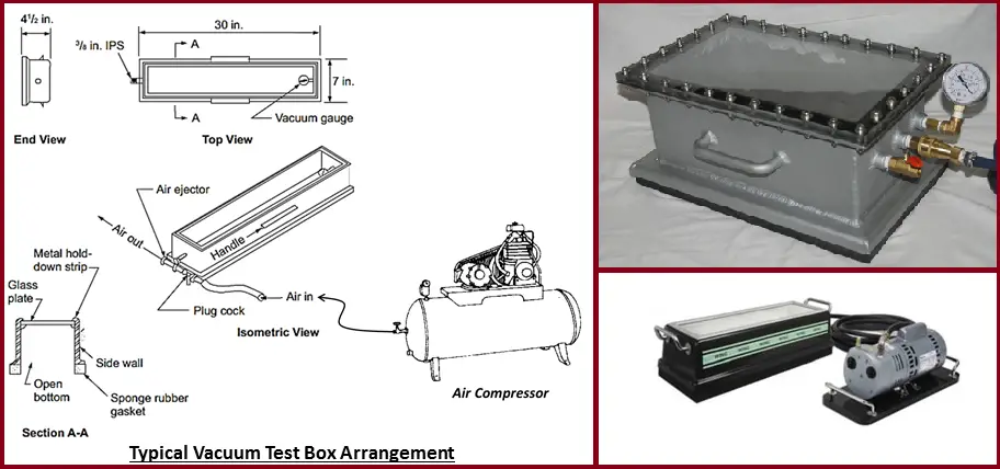
Vacuum box testing is a non-destructive examination (NDE/NDT) used for locating welding leaks. A vacuum box and a compressor create a high or low-pressure vacuum and a detergent solution is applied to the test area. The detergent bubbles help to identify the leaks within the created pressure envelope.
The main objective of the Vacuum box testing technique is to locate leaks in welds due to through-thickness discontinuities. This is accomplished by applying a solution to a weld and creating a differential pressure across the weld causing the formation of bubbles as leakage gas passes through the solution. This testing is to be performed prior to any main vessel or tank testing following the completion of all welding. This article will briefly explain the leak testing procedure using the vacuum box method that can be used for all metals.
Required Equipment for Vacuum Box Testing
The vacuum box test method employs the following equipment for welding checks
a compressor: approximate flow 6 m3 per minute under 7 bar
An air pipe between the compressor and vacuum box.
A vacuum box, which enables it to obtain a depression of 500 m-bar, can be controlled by means of a vacuum manometer located on the box. The manometer shall have a range of 0 psi (0 m-bar) to 15 psi (1020 m-bar).
A liquid detergent mixed with water makes soapy water.
Bubble solution which produces a film. That does not break away from the area to be tested and the bubbles formed shall not break rapidly due to air drying or low face tension.
Soups or detergents for cleaning shall not be used.
If the ambient temperature is below freezing, add ethylene glycol to the solution (antifreeze).
General lighting or individual lighting if necessary. The minimum light level shall be 100 foot-candles (1000 lux)
A brush (diameter not less than 50 mm)
A metallic brush and/or a grinding machine.
Fig. 1 shows a typical vacuum test box arrangement.
Fig. 1: Typical Vacuum Box Testing Arrangement
Vacuum Testing Procedure
Remove weld slag. Mud dirt and other debris from the weld joint may prevent bubble formation. This is achieved, if necessary, by strong brushing.
If freezing weather conditions exist at the time of the test, heat the weld joint to be vacuum box tested until the metal is slightly warm to the hand in order to avoid any ice, that could possibly be plugging existing leaks. Limit the areas heated to those which can be tested before the metal cools to freezing temperatures. The temperature of the part to be examined shall not be below 40 f (5 ˚c) nor above 125 f (52 ˚c ) during the examination.
Provide adequate lighting for this examination.
Apply leak detector soap solution to the weld in a continuous film relatively free of bubbles about 20 inches (500 mm) and on about 4 inches (100 mm) wide. This must be achieved at least 1 minute before applying the vacuum box test.
Put the vacuum box on the area to be examined:
Open the valve of the air ejector.
Press on the vacuum box in order to seat it on the plate.
Check the pressure on the vacuum box manometer: between 204 m-bar (3 psi) and 340 m-bar (5 psi) Note: the API 620 requirement is a partial vacuum of at least 3 psi.
Observe the detector solution for leakage for at least 10 seconds. If there is any leakage, bubbles will appear through the Plexiglas of the vacuum box.
Repeat again the operation after having displaced the vacuum box on the welds to be examined. Overlap successive settings of the vacuum box should be at least 50 to 100 mm ( 2 inches to 4 inches), to assure complete coverage of the weld inspected (thickness of the sponge rubber gasket of the vacuum box is about 30 to 35 mm)
When testing large areas, such as roof or bottom joints, mark inspected areas to prevent missing an area of the weld.
Acceptance Criteria for Vacuum Test Welding
The presence of continuous bubble formation or growth on the surface being examined indicates leakage through an orifice passage(s) in the area under examination. Any indicated leakage shall be considered unacceptable. Some large leaks may not be detected by bubble formation because the strong stream of air may break the bubble film as soon as it forms. To avoid missing this type of leak, the pressure shall be monitored for a variation (decrease).
Repairs after the vacuum test
All indicated leaks, regardless of size, shall be marked and repaired by relieving the pressure, removing the defective weld, and re-welding using qualified welding procedures, welders, and welding operators, and the repaired area shall be retested by the same steps stated above.
Report: For all leak testing by means of the vacuum box testing method, one report is established by the examiner. This report is reviewed and signed by the constructor quality control supervisor.
Technical requirements for Pipes & Fittings for preparation of Purchase Requisition
While preparing the purchase requisition/inquiry of any piping component there are various points that need to be checked and confirmed with the vendor. The responsible requisition engineer should include all the technical points & clauses applicable to the piping components in the requisition/inquiry & subsequent technical queries (TQ).
The requisition engineer should refer to all the project-specific standards and specifications along with the applicable international codes and standards while preparing the inquiry requisition of the piping components. In this article, some general technical requirements for pipes & fittings are listed for information. Note that these requirements may vary depending on the project requirements.
General requirements for Pipe and Pipe-Fittings:
Pipe and Fitting Material supplied must be strictly in accordance with the latest codes and standards, mentioned in the Material Requisition (MR or PR: Purchase Requisition) Scope of supply. This specification for pipes and fittings as detailed in subsequent points shall supplement the codes and other project specifications.
All items must be supplied in accordance with proper wall thickness/ schedule as stated in the Purchase Requisition (PR). Wall thickness thinner or heavier than the specified tolerance shall not be accepted.
The vendor must specify the material type and grade together with NPS and schedule/wall thickness/class within the Material requisition – Scope of Supply for all piping components.
Butt weld end preparation for pipes, fittings, and flanges shall be as per ASME B16.25.
100% radiography has to be performed for all welded items to give a joint factor of 1.0. If not specified, Pipes and fitting shall be supplied as seamless. Seamless is an acceptable alternative for welded pipe and fittings but vice-versa is not acceptable.
The above formula for CE is applicable when the carbon content is greater than 0.12%
CS & LTCS materials shall be fully killed and fine-grained and shall be produced by a low sulfur and low phosphorous refining process. The components must be supplied in normalized or normalized tempered conditions.
All Austenitic stainless steel and duplex stainless steel items must be supplied in the solution annealed and quenched condition as per corresponding ASTM standard.
Repair welding for the parent plate/weld end flange is not accepted.
The carbon content of SS 316 must be limited to 0.03%. All SS Materials specified as F 316 / WP 316/ Type 316 may be dual-certified for both SS 316 & 316L if specifically mentioned in the project specification.
Austenitic stainless steel has to be capable of passing an intergranular corrosion test in accordance with ASTM A262, Practice E.
All duplex stainless steel shall have ferrite content between 35% – 65% (volume fraction) on base metal and on heat affected zone to 35% – 70 % as per ASTM E562 four-point count method.
Requirements for Pipes:
Dimensions of CS / SS and Alloy steel (AS) pipe shall comply with ASME B36.10M or ASME B36.19M as applicable.
CS pipes shall be supplied in double random lengths (11 to 13m) for pipe sizes 2” to 36”, and in single random lengths (5 to 7m) for pipe sizes 1.5” and smaller.
SS, Duplex Stainless Steel (DSS), and Carbon Steel galvanized pipes shall be supplied in single random lengths (5 to 7m) for all pipe sizes.
It is not permitted to join lengths of pipe by circumferential welds to make single or double random lengths.
Plain end pipes must have square ends cut with burrs removed.
All stainless steel pipes shall be supplied in solution-annealed condition.
All threaded & coupled pipes shall be supplied with ends threaded in accordance with ASME B1.20.1 (NPT).
Each length of the threaded pipe shall be supplied with full coupling screwed hand-tight at one end.
Galvanizing of pipes shall be in accordance with ASTM A153. The threaded portion of pipes shall be free of galvanizing.
Pipes shall be heat treated in accordance with product specification requirements after completion of all forming and welding operations.
Carbon Steel & Low-Temperature Carbon Steel (LTCS) Pipes shall be fully killed fine-grained and shall be supplied in normalized or normalized and tempered conditions.
Welded pipe shall be supplied with a single straight seam for sizes up to 36” and a double straight seam for sizes greater than 36” subject to approval from the contractor.
Spiral seam welds are not acceptable.
All DSS welded pipes with a wall thickness greater than 30 mm must be 100% ultrasonically examined.
Requirements for Fittings:
Dimensions of butt welded fittings must be in accordance with ASME B16.9.
Other fittings dimensions shall comply with MSS SP-75, MSS SP-95, MSS SP-97, or BS 3799 as applicable.
The vendor shall provide calculations as per ASME B31.3 for the fittings not covered under the above-mentioned standards.
Union dimensions shall be in accordance with BS 3799.
All screwed fittings shall be threaded NPT in accordance with ASME B1.20.1.
Branch reinforcing fittings (i.e. Elbowlets, Sockolets, weldolets, etc.) shall be designed in accordance with the requirements of ASME B31.3. The vendor shall submit drawings during the bid stage and calculations for review and approval after awarding the contract.
Butt weld elbows shall be long radius type (radius =1.5 nominal pipe size). Short-radius elbows are not permitted.
For reducing fittings specified with two schedules in the Inquiry / Purchase description, the first schedule refers to the larger end or run pipe, the second schedule refers to the smaller end or branch pipe.
Fittings shall be forged to the final shape and size. Fittings shall not be machined from bar stock or solid forged billets without specific approval.
Galvanizing of fittings shall be in accordance with ASTM A153. The threaded portion of fittings shall be supplied with threads free of galvanizing.
Swage nipple shall be pipe swaged by forging only. Machining of bar stock, forgings, or heavy wall pipe is not permitted. Dimensions shall be in accordance with MSS-SP-95.
All reduction sizes for tees and reducers are to be in accordance with ASME B16.9.
CS & LTCS fittings shall be fully killed and fine-grained and shall be supplied in normalized or normalized tempered conditions.
100% of CS & LTCS welded fittings, with wall thickness greater than Sch 80 shall be examined by Magnetic Particle Examination for weld bevel ends. Acceptance standards shall be in accordance with ASME VIII Division 1, Appendix 6. This shall be done after the final heat treatment.
100% of SS & DSS wrought fittings having a wall thickness of more than 20 mm shall have the bevel and weld end over a width of 25mm, examined by the Dye penetrant Method. Acceptance standards shall be in accordance with ASME VIII Division 1, Appendix 8.
100% of DSS welded fittings with a wall thickness greater than 30mm shall be 100% ultrasonically examined in accordance with ASME VIII Division 1.
100% of DSS forged fittings weld bevels shall be examined by Dye Penetrant inspection.
100% of CS, LTCS & SS forged fittings, with wall thickness greater than Sch 80 shall be examined by Magnetic Particle / Dye penetrant examination. Acceptance standards shall be in accordance with ASME VIII Division 1, Appendix 6 / 8. This shall be done after the final heat treatment.
Positive material identification:
Positive Material Identification (PMI) shall be conducted for all SS / CRA alloy piping items as per the project specification included in the Inquiry / Purchase requisition.
Special Requirements:
Sour service requirements:
All materials specified for sour service shall, as a minimum, meet the requirements of NACE MR0175 / ISO 15156 – latest edition.
All welded pipes/fittings in sour service shall be HIC tested, if required by the project specification. It shall be conducted for one pipe/fitting per heat in accordance with NACE TM-0284 Solution – A with acceptance criteria as specified in NACE MR-0175.
Impact test requirements:
All CS, LTCS, welded austenitic, and duplex stainless steel piping components shall be impact tested (for use in low-temperature services) in accordance with ASME B31.3.
For carbon steel pipes and fittings, the impact test temperature shall be the ‘minimum metal temperature’ as defined in the project. The impact test requirement and acceptance criteria shall be as per Cl. 323.2.2 and Cl. 323.3.5 of ASME B31.3 respectively.
For welded SS and DSS items, the impact test temperature shall be the ‘minimum metal temperature’ as defined in the project but not more than (-101 Deg. C) and (-50 Deg. C) respectively. For SS items, the acceptance criteria shall be as per Cl. 323.3.5 of ASME B 31.3. For DSS items, test results shall be at least 40 joules in the transverse direction (for standard specimen 10 x 10 mm) as an average of three tests, one result may be lower but not less than 30 joules.
For LTCS items, the impact test temperature shall be (-46 Deg. C). Test results shall be at least 27 joules as an average of three tests (for standard specimen 10 x 10 mm), one result may be lower, but not lower than 21 joules.
Online Video Course on Piping and Pipe Fittings
To enrich yourself with piping and pipe fitting details you can opt for the following online video courses
ORP stands for oxidation-reduction potential, which is a measure, in milli-volts, of the tendency of a chemical substance to oxidize OR reduce another chemical substance.
OXIDATION: Oxidation is the loss of electrons by an atom, molecule, or ion.
REDUCTION: Reduction is the net gain of electrons by an atom, molecule, or ion.
OXIDATION: Fe = Fe+2 + 2 e- (Half- Reaction)
REDUCTION: Cl2 + 2 e- = 2 Cl- (Half-Reaction)
OVERALL REACTION: Fe + Cl2 => FeCl2
In the reaction above, iron (Fe) reduces chlorine (Cl2) and is called a reductant or reducing agent. Conversely, chlorine (Cl2) oxidizes iron (Fe) and is called an oxidant or oxidizing agent:
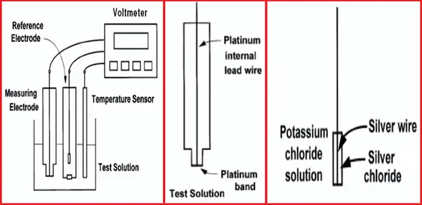
ORP Measurement
The cell consists of a measuring and reference electrode.
The voltage between the electrodes is the ORP of the test solution.
Although the electrodes are shown separately, in most processes ORP sensors, the electrodes, and the temperature element are combined into a single sensor.
Because ORP depends on temperature, the temperature at which the measurement is made must be reported.
Measuring Electrode
An ORP electrode (Fig. 1) is a piece of noble metal, usually platinum,
but sometimes gold, attached to the end of a glass tube. The potential of the electrode is controlled by the ratio of oxidized to reduced substances in the sample. pH and other constituents in the sample may also affect ORP.
The Reference Electrode
The reference electrode used for ORP measurements is typically the same silver-silver chloride electrode used with pH measurements. In contrast with pH measurements, some offset in the reference is tolerable in ORP since, as will be seen, the mV changes measured in most ORP applications are large.
In certain specific applications (for example, bleach production), an ORP sensor may use a silver billet as a reference, or even a pH electrode.
Fig. 1: ORP Measurement
The electrode behavior is described by the Nernst equation:
Em = E o – (RT/nF) ln {[ox] / [red]}
Where,
Em is the potential from the ORP electrode,
Eo is related to the potential of the reference electrode,
R is the Gas Law constant,
F is Faraday’s constant,
T is the temperature in Kelvin,
n is the number of electrons,
[ox] is the oxidant concentration in moles/L, and
[red] is the reductant concentration in moles/L.
Why is ORP Measured?
Applications of the ORP measurement are not nearly as widespread as those of pH, but several reasonably standard applications exist.
Bleaching operations
Manufacture of bleach
Oxidation of cyanide wastes
Reduction of chromate wastes
Temperature Effects on ORP Measurement
The temperature has 2 distinct effects on ORP measurements:
Electrodes will have a different output potential at different temperatures for a given ratio of ionic activity.
Ionic activity is affected, arising from temperature effects on dissociation, activity coefficients, and interactions between ions in solution.
In general, however, ORP measurements are not compensated for temperature effects due to the fact that:
The isopotential point (the point of thermal independence) of ORP systems is specific only for that particular redox reaction (i.e. there is no “standard” point for all ORP reactions).
The chemistry of the redox reaction can be quite complex, especially if several ionic species involving varying numbers of electrons transferred (thus varying values for n within one equation) contribute to the reaction/oxidation-reduction potential.
Most ORP measurements are done at constant temperatures, such as in process measurement and control.
How to Approach ORP Applications?
Regardless of the nature of the application under consideration, the steps to follow are the same:
Look up the half-reaction(s) of the redox couple(s) involved in the application in a handbook of chemistry or other references.
Not all of the chemical substances involved in the half-reaction and their concentration range in the application under consideration.
Substituting their minimum and maximum concentrations into the Nernst equation can provide the contribution of each substance to the overall ORP.
If an oxidation-reduction reaction is being monitored or controlled, the equivalence point can be calculated over the pH range of the process.
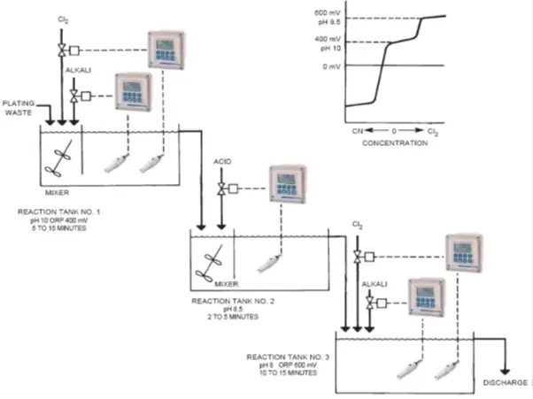
ORP -Cyanide Treatment in Metal Industry
Fig. 2: Cyanide Treatment in Metal Industry
PROCESS: One of the most effective means to treat these waste materials is to destroy the cyanide with chlorine.
This process is accomplished in two stages:
Cyanide is oxidized to cyanate, using pH and ORP control.
Cyanate is oxidized to nitrogen and carbon dioxide, harmless gases, that can be safely discharged into the environment. This stage also uses pH and ORP control.
OXIDATION OF CYANIDE TO CYANATE:
In the first reaction tank, the pH of the waste is measured, and caustic (NaOH at 50% strength) is automatically injected to raise the pH to 10 or higher.
The oxidation-reduction potential (ORP) of the waste is measured, and chlorine gas (Cl2) is automatically injected to raise the ORP to 400 mV or higher.
The following reaction occurs, taking from 5 to 10 minutes:
NaCN + Cl2 + 2NaOH NaCNO + 2NaCl + H2O
DESTRUCTION OF CYANATE TO NITROGEN AND CARBON DIOXIDE:
In the second reaction tank, the pH of the waste is measured, and acid is injected to lower the pH to 7-8.
This process takes 2 to 5 minutes. In the third reaction tank, the ORP of the waste is measured and chlorine gas (Cl2) is automatically injected to raise the ORP to 600 mV or higher (Meanwhile the pH controller maintains the set-point at 7-8, correcting for any acidity created by the addition of the chlorine gas).
The following reaction occurs, taking 10 to 15 minutes:
2NaCNO + 3Cl2 + 4NaOH 6NaCl + 2CO2 + N2 + 2H2O
The cyanide is eventually converted to harmless materials by the above reaction and the waste can be discharged.
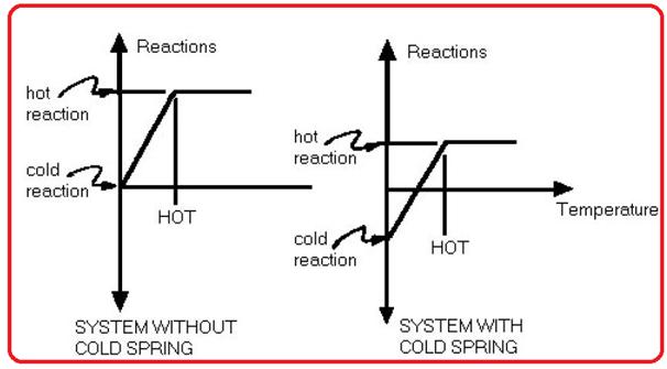
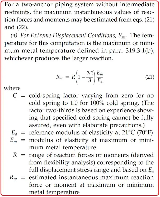
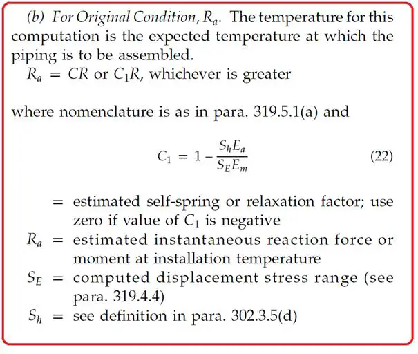
Cold Spring is the process of intentional deformation (usually accomplished by cutting short or long the pipe runs between two anchors) of piping during assembly to produce a desired initial displacement and stress. Cold Spring is the intentional stressing and elastic deformation of the piping system during the election cycle to permit the system to attain more favorable reactions and stresses in the operating condition.
Why Cold Spring?
Cold Springs can help to
Reduce the hot stresses to mitigate the creep damage.
Reduce the hot reaction forces on connecting equipment.
Control the movement space.
Actual use of Cold Spring
The general belief is that the additional creep damage caused by the initial thermal expansion stress (due to cold pull) is insignificant if the total expansion stress range is checked within the allowable limit. Also, the code does not allow us to take advantage of cold springs in reducing stresses.
The control of the movement space is secondary.
Thus the real gain of cold spring has become the reduction of the hot reaction on the connected equipment.
A system without Cold Spring Vs System with Cold Spring:
Fig. 1: System without Cold Spring Vs System with Cold Spring
End Reaction at Design Temperature (as per B31.3):
Fig. 2: End Reaction at Design Temperature (as per B31.3)
End Reaction at Installation Temperature (as per B31.3):
Fig. 3: End Reaction at Installation Temperature (as per B31.3)
The use of the above equations is valid for a two-anchor piping system without intermediate restraints
For multi-anchor piping systems and for two-anchor systems with intermediate restraints above equations (21 and 22 as per B31.3) are not applicable.
Each case must be studied to estimate the location, nature, the extent of local overstrain, and its effect on stress distribution and reactions.
Code allows us to apply cold spring credit in calculating the thrusts and moments where actual reactions, as well as their range of variations, are significant.
Code restricts us from applying cold spring credit in stress range calculations. This is because the piping system is affected more by the range of stress variation than by the magnitude of stress at a given time.
Where cold spring is used in the piping system, experience has shown that it cannot be fully assured. Therefore, the reactions shall be computed for two cases. First, with the assumption that only two-thirds of the design cold spring is present, and second, with the assumption that four-thirds of the design cold spring is present. That effectively suggests calculating and comparing the end reactions from a couple of Caesar runs. First being one with only two-thirds of the cold spring and another using four-thirds. The results in both cases should be satisfactory. This is especially valid for computer analysis.
Both the sustained loads and the operating loads should be within the manufacturers’ allowable for the particular piece of equipment.
Cold Spring factor (C)
The following procedure explains how to get cold spring factor –
Understand the system and decide in which direction the application of cold spring will give us maximum benefit.
Get the maximum displacement corresponding to the direction in which the cold spring is planned. This can be found in the displacement report using Caesar II.
The factor is then decided by the amount of cold spring applied to the system with respect to the expansion.
A 100 percent cold-sprung system will have zero loads in expansion cases.
The oil and gas industry is a complex and multifaceted sector that relies heavily on various types of equipment to ensure efficient and safe operations. All the equipment can be categorized into two groups; static equipment and rotary equipment. Among these, static equipment plays a crucial role in processing, storing, and transporting hydrocarbons.
The majority of mechanical types of equipment found in oil and gas facilities belong to the static equipment group, which comprises pressure vessels, heat exchangers, storage tanks, fired Heaters, pig launchers, etc. In this article, we will briefly describe some of the static equipment.
What is the Static Equipment?
Static equipment refers to the fixed machinery and components that do not undergo significant movement during their operation. They are also known as stationary equipment. Unlike rotating equipment, such as pumps and turbines, static equipment remains stationary, often functioning under high pressures and temperatures. This category includes:
Pressure Vessels
Heat Exchangers
Storage Tanks
Columns and Towers
Reactors
Flares
Types of Static Equipment
Depending on the purpose they serve, there are various types of static equipment. Some of the most common stationary types of equipment are:
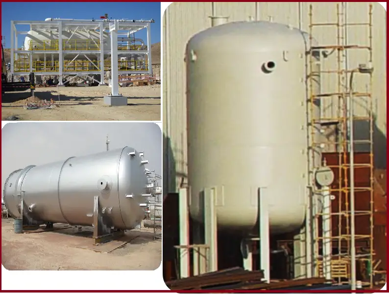
1. Horizontal & Vertical Pressure Vessel:
A pressure vessel is a container designed to hold fluids, i.e, gases or liquids, at a pressure substantially different (higher or lower) from the ambient pressure. They are either vertical or horizontal. Pressure vessels are designed following ASME BPVC codes. In oil and gas applications, they are often used for:
Storage: Storing hydrocarbons and chemicals under pressure.
Separation: Facilitating the separation of oil, gas, and water.
Fig. 1: Horizontal & Vertical Pressure Vessel
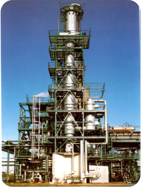
2. Columns and Towers:
Columns and towers are tall vertical pressure vessels. They have internals like trays, packing, distributors, demisters, etc. for separation and other applications. Used primarily in refining processes, columns and towers facilitate the separation of different components through distillation. They play a key role in:
Absorption and Stripping: Removing impurities or desired components.
Fractionation: Separating crude oil into its constituent parts.
Fig. 2: Column
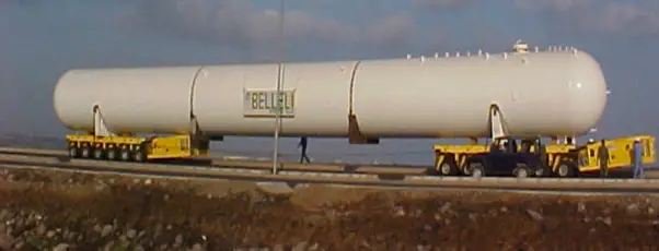
3. Buried/ Mounded Storage Bullets:
Bullets are large, high-pressure storage vessels. Generally used for storing LPG / LNG. Buried / Mounded to safeguard against any accident. They are designed based on API 620.
Fig. 3: Storage Bullets
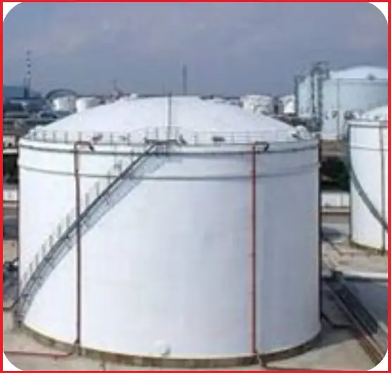
4. Atmospheric Storage Tanks:
Storage tanks are large, atmospheric-pressure storage equipment. Depending on the fluid stored, the tank roof design will be of the fixed roof or floating roof type. Click here to learn more about various atmospheric storage tanks. Storage tanks hold crude oil, refined products, and other chemicals. Designed following API 650, they come in various designs, including above-ground and underground tanks, and serve multiple purposes:
Safety: Providing safe storage of hazardous materials.
Buffer Storage: Managing supply and demand fluctuations.
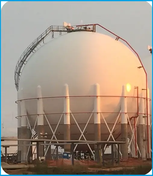
A spherical storage tank is a type of tank used to store liquids or gases under pressure. Its spherical shape provides strength and minimizes surface area, which reduces the risk of leaks and structural failure. These tanks are commonly used for storing liquefied gases like propane and butane.
Spheres are very large, high-pressure storage equipment. Generally used for storing huge quantities of LPG / LNG / NGL. Spherical storage tanks are designed following API 620.
Fig. 5: Pressurized Spherical Tank
6. Heat Exchangers
Heat exchangers transfer heat between two or more fluids, critical for:
Cooling: Reducing the temperature of process streams.
Heating: Preheating feedstock to optimize reaction rates.
The most common heat exchangers used in the oil and gas industries are
Most commonly used heat exchanger. Used for high-pressure, high-duty applications. A shell and tube heat exchanger consists of a series of tubes, one set carrying the hot fluid and the other carrying the cold fluid. The heat exchange occurs as the fluids flow past each other, allowing for efficient thermal transfer. This design is widely used in oil refineries and chemical plants.
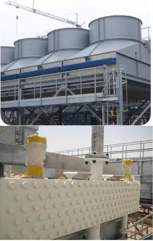
Also called dry-type cooling towers, air is used as a cooling medium. An air-cooled heat exchanger uses ambient air to cool process fluids. It typically consists of finned tubes through which the fluid flows, and a fan to enhance air circulation. These exchangers are often used in locations where water is scarce or for cooling high-temperature fluids.
Fig. 6: Air Cooled Heat Exchanger
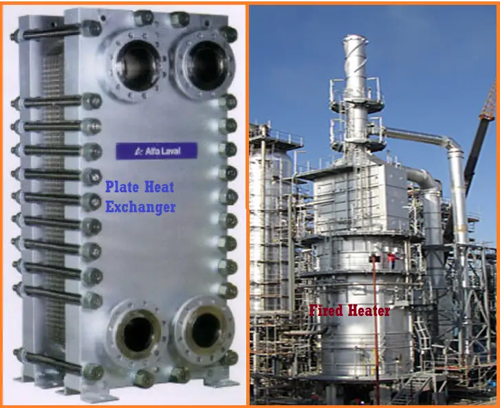
6.3 Plate Type Heat Exchangers (Fig. 7):
A compact type heat exchanger, used for medium-pressure, high-duty applications. It can work with very low approach temperatures. A plate type heat exchanger comprises thin plates arranged in a stack to create channels for the fluids. The design allows for a large surface area for heat transfer while minimizing the volume. This type is known for its efficiency and is commonly used in various process industries, including oil and gas.
7. Fired Heaters (Fig. 7):
A fired heater comprises a furnace where the flame impinges directly on the tubes/surfaces containing the fluid to be heated, which include process fluid, thermic fluids, air, water, and so on.
The furnace is also called a radiant zone as major heat transfer is by radiation, followed by the convection zone wherein the heat transfer is predominantly by convection.
Fig. 7: Plate Heat Exchanger and Fired Heater
8. PIG Launchers / Receivers:
A pig launcher is a device that uses a pressurized container to shoot a cleaning device (“pig”) through the pipeline to perform a variety of functions including cleaning, monitoring, and maintaining the pipe.
Fig. 8: Pig Launcher
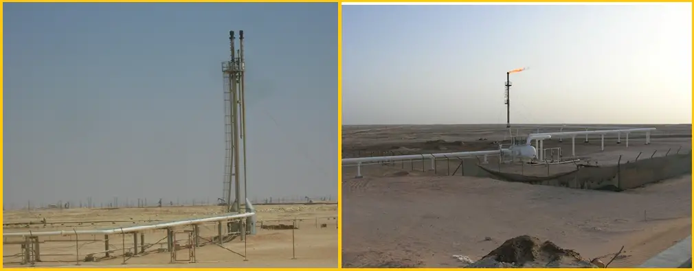
9. Flare Stack and Flare:
A flare stack is a safety device used to burn off excess hydrocarbons that cannot be processed or captured. This prevents the accumulation of flammable gases, reducing explosion risks. Flare stacks are essential in maintaining safety and environmental compliance. Fig. 9 below shows an example of a flare stack.
Fig. 9: Flare Stack and Knock out Drum
10. Knock Out Drum:
A knock out drum (Fig. 9) is a vessel designed to separate liquids from gases in a pipeline system. It allows for the removal of liquids that may condense from gases, ensuring that only vapor enters downstream equipment. This prevents damage and ensures optimal operation.
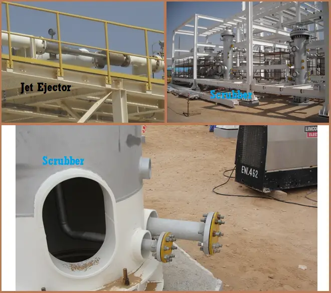
11. Jet Ejector:
A jet ejector is a device that uses a high-velocity jet of fluid to create a vacuum or to mix fluids. It is often used in applications like transporting fluids and gas, separating phases, or creating suction for gas lifting in oil wells.
Fig. 10: Jet Ejector and Scrubber
12. Scrubber
A scrubber is a device used to remove pollutants or particulates from gas streams. In the oil and gas industry, scrubbers are used to clean process gases and prevent emissions of harmful substances, enhancing environmental compliance.
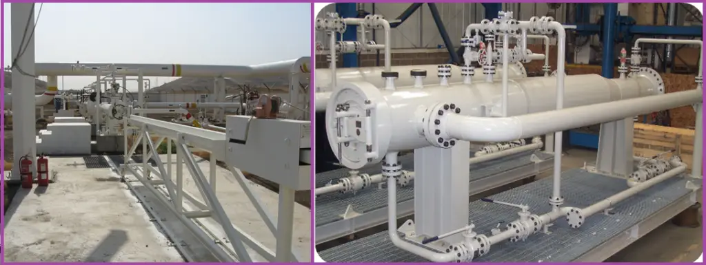
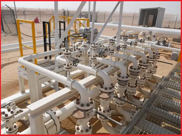
13. MSV Skid:
A multiport valve skid (MSV skid) is a compact, pre-assembled system designed to manage the flow of fluids in various directions within a pipeline network. It incorporates multiple valves—often including gate, ball, or check valves—configured in a single unit. Fig. 11 below shows a typical diagram of MSV skid.
Fig. 11: MSV Skid
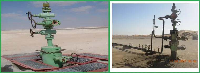
14. Wellhead:
A wellhead is the structure at the surface of a well that provides the interface for drilling and production equipment. It contains valves, gauges, and fittings to control the flow of oil or gas and ensure safety during extraction.
Fig. 12: Wellhead
15. Boilers
Boilers are vessels used to generate steam or hot water by heating a fluid. In the oil and gas industry, they are often used for providing steam for processes, heating, and driving turbines.
16. Filters
Filters are devices used to remove particulates, impurities, and contaminants from fluids. In oil and gas operations, filters help maintain the quality of process fluids and protect equipment from damage.
17. Furnace
A furnace is an industrial heating device used to raise the temperature of materials or fluids. In oil refining, furnaces are used to heat crude oil before it enters the distillation column.
18. Reactors
Reactors are vessels where chemical reactions occur to convert raw materials into products. In the oil and gas industry, reactors can be used for processes like cracking and reforming hydrocarbons.
19. Deaerator
A deaerator is a device used to remove dissolved gases (mainly oxygen) from water or other fluids, preventing corrosion in boilers and other equipment. It enhances the efficiency and longevity of systems using water.
20. Steam Drums
Steam drums are vessels in a steam generation system that separate steam from water. They play a crucial role in ensuring the quality of steam used in processes and are commonly found in boiler systems.
21. Static Mixer
A static mixer is a device used to mix two or more fluids without moving parts. It typically consists of a series of stationary elements that create turbulence, ensuring uniform mixing. These are often used in chemical processing and oil refining.
22. Surge Tank
A surge tank is a vessel used to absorb changes in pressure and flow within a system, protecting equipment from pressure fluctuations. It helps maintain system stability in pipelines and processing units.
23. Electrostatic Precipitator
An electrostatic precipitator is a device that removes particulate matter from gas streams by charging particles and collecting them on plates. This is crucial for reducing emissions and meeting environmental standards.
24. Coalescer
A coalescer is a device used to separate immiscible liquids, such as water from oil. It allows smaller droplets to merge into larger ones, making separation easier. Coalescers are vital in oil refining and processing.
25. Separator
A separator is a vessel that separates different phases of a mixture, typically oil, gas, and water. In the oil and gas industry, separators are essential for ensuring product purity and quality.
26. Demister
A demister is a device used to remove mist or small droplets from gas streams. It is often employed in conjunction with separators to enhance product quality by ensuring that gas is free from liquid contaminants.
27. Cyclone
A cyclone is a separation device that uses centrifugal force to separate particles from a gas or liquid stream. Cyclones are commonly used for removing dust or solid particulates in gas streams.
28. Silo
A silo is a large storage structure used for holding bulk materials, such as solid fuels or chemicals. In the oil and gas industry, silos may store solid materials used in drilling or processing.
29. Electrolyzer
An electrolyzer is a device that uses electricity to split water into hydrogen and oxygen through electrolysis. In the oil and gas industry, electrolyzers are gaining attention for producing hydrogen, which can be used as a clean fuel or in refining processes.
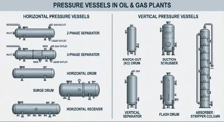
Fig. 13: Pressure Vessels in Oil and Gas Plants
Importance of Static Equipment in Oil and Gas Operations
The reliability and efficiency of static equipment directly impact the overall safety, productivity, and profitability of oil and gas operations. Here are some key reasons why they are indispensable:
Safety: Properly maintained static equipment reduces the risk of leaks, explosions, and other hazardous incidents, safeguarding workers and the environment.
Regulatory Compliance: Adherence to industry regulations and standards is critical to avoid penalties and ensure safe operations.
Cost Management: Investing in the maintenance of static equipment can prevent costly repairs and operational disruptions down the line.
Hence, static equipment forms the backbone of operations in the oil and gas industry. These components are essential for processes such as separation, storage, and heat exchange, playing a crucial role in the efficiency and safety of operations, particularly in the oil and gas industry.
FAQ regarding Static Equipment
What Are The Static Equipment Used in a Refinery?
Static equipment in a refinery includes components that do not have moving parts during normal operation. Common examples are:
Storage Tanks: For crude oil and refined products.
Heat Exchangers: For transferring heat between fluids.
Pressure Vessels: Including reactors and separators.
Pipes and Pipelines: Used for transporting fluids.
Columns: Such as distillation columns for separation processes.
Is Valve A Static Equipment?
Valves are typically classified as dynamic equipment because they control the flow of fluids and have moving parts. However, in the context of EPC organizations, a valve is considered a piping item, not equipment.
Are Piping and Pipeline Static Equipment?
In the context of EPC organizations, piping, and pipelines are considered different from equipment categories. So, there is confusion regarding whether piping and pipelines are to be considered static equipment or not.
Is A Separator Static Equipment?
Yes, separators are classified as static equipment. They are designed to separate different phases of a mixture (such as oil, gas, and water) without any moving parts during the separation process.
Is A Compressor Static or Rotary?
A compressor is classified as rotary equipment. It has moving parts that compress gases to increase their pressure.
What Is Static Equipment Engineering?
Static equipment engineering involves the design, analysis, and maintenance of equipment that does not have moving parts. This includes ensuring structural integrity, pressure vessel design, heat transfer efficiency, and compliance with safety regulations.
Which is the most widely used static equipment in the oil and gas industry?
The most widely used static equipment in the oil and gas industry includes storage tanks and pressure vessels, as they are essential for the storage and processing of hydrocarbons.
What is the difference between static and rotary equipment?
The primary difference lies in their operational characteristics:
Static Equipment: Does not have moving parts; examples include tanks, heat exchangers, and separators.
Rotary Equipment: Contains moving parts and performs work on fluids; examples include pumps, compressors, and turbines.
What is the normal flow for static equipment design?
The normal flow for static equipment design includes several steps:
Define Requirements: Understand the operational requirements and specifications.
Select Material: Choose appropriate materials based on fluid properties and environmental conditions.
Design Calculations: Perform necessary calculations for pressure, temperature, and structural integrity.
Draft Design: Create detailed engineering drawings and specifications.
Review and Approvals: Ensure compliance with industry standards and obtain necessary approvals.
What is static plant equipment?
Static plant equipment refers to the fixed installations in a facility that are essential for processing and storing materials. This includes all static equipment like storage tanks, heat exchangers, reactors, and pipelines that support the refinery operations without moving parts during normal function.
What Are the Common Materials Used in Static Equipment?
Common materials for static equipment include carbon steel, stainless steel, and various alloys. The choice depends on factors such as temperature, pressure, and the corrosiveness of the fluids involved.
How is the Maintenance of Static Equipment Different from Rotary Equipment?
Maintenance of static equipment often focuses on inspections for structural integrity, corrosion, and leakage, while rotary equipment maintenance may involve lubrication, alignment, and wear monitoring of moving parts.
What Standards Govern the Design of Static Equipment?
Design standards for static equipment are governed by various codes and regulations, such as ASME (American Society of Mechanical Engineers) for pressure vessels and API (American Petroleum Institute) standards for tanks and pipelines.
What Factors Influence the Design of Static Equipment?
Key factors include the type of fluid being processed, operating temperature and pressure, environmental conditions, and safety regulations.
What Is the Role of Static Equipment in Process Safety?
Static equipment plays a crucial role in process safety by containing fluids under pressure, preventing leaks, and ensuring safe storage and handling of hazardous materials.
Can Static Equipment Be Used for Dynamic Processes?
While static equipment is primarily designed for steady-state operations, some components (like heat exchangers) can also be involved in dynamic processes, such as fluctuating flow rates, under certain conditions.
How Do You Determine the Lifespan of Static Equipment?
The lifespan of static equipment is determined by factors like material degradation, maintenance practices, operational conditions, and adherence to safety standards.
What Are the Challenges in Designing Static Equipment?
Challenges include managing thermal expansion, ensuring structural integrity under pressure, preventing corrosion, and optimizing for efficiency while adhering to safety regulations.
How Do You Ensure Compliance with Environmental Regulations for Static Equipment?
Ensuring compliance involves conducting environmental impact assessments, implementing leak detection systems, and adhering to regulations set forth by local and national environmental agencies.