Some users of START-PROF Piping Stress Analysis software ask the same question:
Why loads and displacements are not zero in a cold state?
I will try to explain this phenomenon in this article.
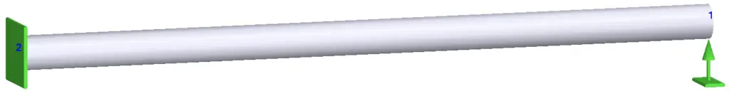
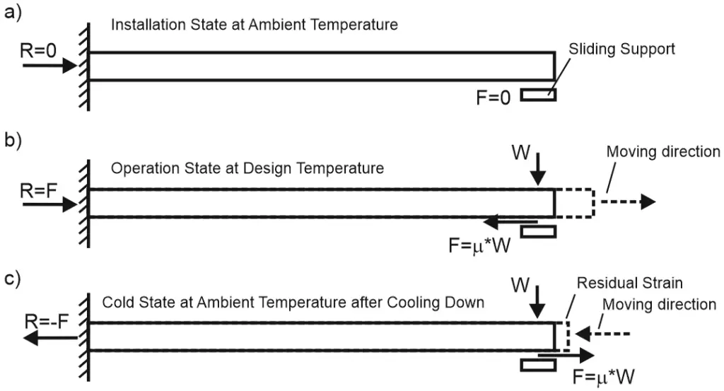
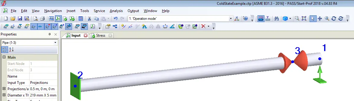
Let’s imagine the simple piping model – console pipe. Anchor on the left end and free end with sliding support at the right.
In installation state (a) at ambient temperature friction forced doesn’t exist because there are no displacements. The anchor load R is zero.
In operation state (b) pipe elongates and the right end slides in the right direction. The friction force is always directed in the opposite direction of movement. Therefore friction force direction is from right to left. The friction force value is F= µ *W, where W is the support load from the weight load, and µ is the friction factor. The anchor load is R=F.
Will friction force and support load R exist in a cold state (c) or not? The answer is yes! The right end of the pipe will slide to the left direction during cooling down. The friction force will change its direction to the right. When the pipe will reach the ambient temperature friction force will not disappear. The anchor load will be R=-F. The effect of friction forces in cold conditions looks like the cold spring effect. The pipe remains under tension, support loads are not zero.
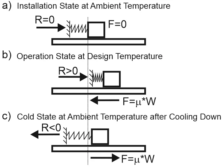
This phenomenon can also be illustrated using the heavy brick and spring. We push the brick in the right direction (b) and then pull it back into the left direction (c). The spring in cold conditions (c) will remain stretched. Reaction force R will be not zero.
Should we consider this effect during pipe stress analysis calculations? Yes!
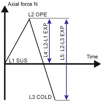
Usually, when engineers perform pipe stress analysis, the friction forces in the cold state are assumed to be zero. The following load cases can be created:
L1: W+P SUS L2: W+P+T OPE L3: L2-T COLD (follow up L2) L4: L2-L1 EXP L5: L2-L3 EXP
Usually, we calculate the expansion stress range L4 between the operation condition (L2) and installation condition (L1). But what if we will calculate the expansion stress range (L5) between the operation condition (L2) and cold condition (L3)? Will it be greater or lower?
In operating condition L2, the stress due to friction is compressive S=-F/A. In installation condition L1, the stress is zero S=0. In cold condition L3 the stress is tensile S=+F/A. This means that L4 expansion range will give SA=ABS(-F)/A=F/A, but L5 expansion range will give SA=ABS(-F+F)/A=2*F/A.
Expansion range L5 is 2 times greater than L4! It’s more correct to calculate the expansion range between the operation and cold state (L2-L3) with friction instead of the operation state and installation state without friction (L2-L1).
Friction factor decrease after several movements. Thus sometimes friction factor for L5 stress range calculation is required to be decreased by 1/2 from the full value. For example, if the friction factor for the L2 load case is µ =0.3, then for L3 we should use µ =0.3*0.5=0.15. In this case, the stress range L5 will be SA=ABS(-F+0.5F)/A=1.5*F/A.
How to model it in START-PROF?
Let’s check how to calculate this in PASS/START-PROF software. Create a new simple model, pipe with an anchor on the left end and sliding support with a heavy valve on another end.
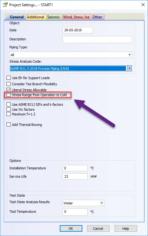
Modeling the cold state with friction is a standard function of the START-PROF operation mode editor.
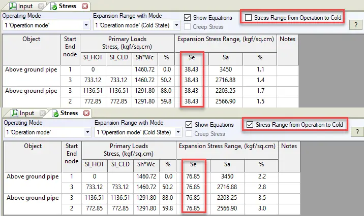
If the option “Stress Rang from Operation to Cold” is turned off, START-PROF will calculate stress range L4 (between operation L2 and installation L1). If we turn on this option, START-PROF will calculate stress range L5 (between operation L2 and cold L3) considering the backward friction effect.
In the stress table we can see, that the stress range is 2 times greater for stress range operation-cold L5 than for operation-installation L4.
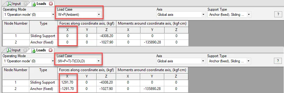
Let’s compare support loads in Installation state L1 and Cold state L3. In the installation state, the support load in the X direction is zero. But in a cold state, it is not zero and equal to the friction force on sliding support.
In some cases, the friction effect may give even greater nozzle loads in a cold state than in a hot state.
After the second heating of the complex piping system, the displacements will be slightly different from the displacements during the first heating up. The same situation with second, third, etc. cycles.
What if we have several warming and cooling cycles?
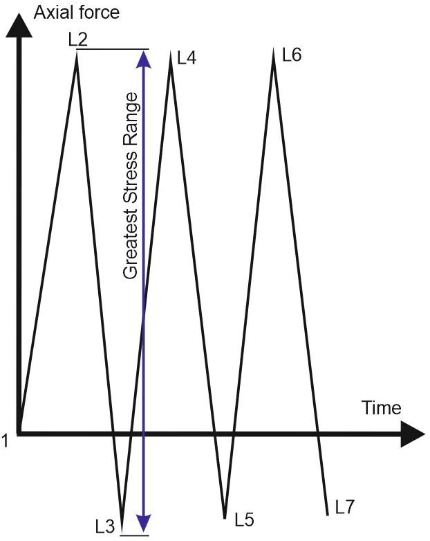
Let’s imagine that we have several heating and cooling cycles
L1: W+P SUS L2: W+P+T OPE L3: L2-T COLD (following up L2) L4: L3+T OPE (following up L3) L5: L2-T COLD (following up L4) L6: L3+T OPE (following up L5) L7: L2-T COLD (following up L6) L8: L3+T OPE (following up L7) …
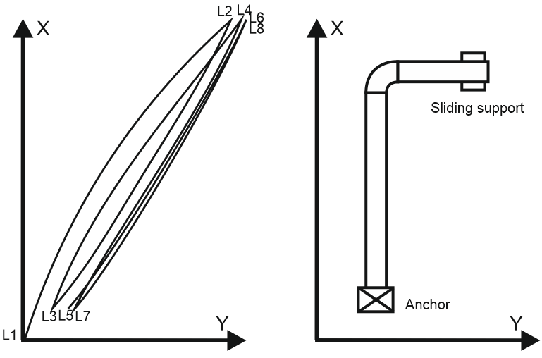
For the L-shape piping model, the sliding support displacements diagram in the XY plane has the following shape:
The greatest loads will be at the first cycle L2-L3. The greatest stress range will be L2-L3. The L1-L2 range is not the greatest.
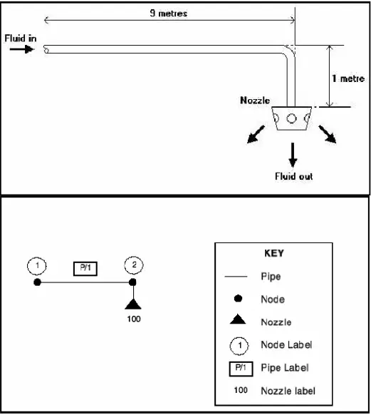
In general, piping networks consist of a number of piping components (Pipes, Ducts, Pumps, Valves, Filters, Orifice Plates, Fixed Pressure Drops, and Nozzles) all connected together. The points at which the components may be joined to other components are referred to as nodes. Consider, for example, the simple system shown below, which consists of a single pipe with a nozzle on one end. Fluid enters the open end of the pipe and is discharged through the nozzle.
This network can be represented schematically by the diagram shown below (Fig. 1)
Fig. 1: Schematic representation of a Piping Network
Labeling Diagram of a piping network
Notice how the pipe, nozzle, and nodes have each been given a label. When preparing a network for simulation every component and every node must be given a label that identifies it uniquely. The production of a fully labeled schematic diagram is an essential part of any simulation. Labels may either be tagged or untagged. Tags can be used to make labels more meaningful, and to allow sections of large networks to be more easily identified. In our schematic diagram, we have labeled the pipe as P/1(tagged label), the nozzle as 100 (untagged label), and the nodes as 1 and 2(untagged label).
Inlets and Outlets of a piping network
In the drawing of a network, each pipe, pump, valve, and filter component should have two nodes (one at each end). One of these nodes is designated the component’s input node and the other is designated its output node. Note that fluid does not necessarily flow from the input node to the output node.
On the other hand, low velocities increase pipe diameter (Increase the total cost) and also increase the possibility of illuviation (Sedimentation) in a piping system.
For fluid velocities of different systems, it is better to refer to the piping handbooks.
Pressure drop Criteria:
Generally, it is preferable to reduce the pressure drop in the piping system as far as possible because :
-To decrease the size of the pump or compressor (Cost reduction).
-To reduce the initial pressure (i.e. in case of gravity flows).
-To decrease energy losses.
-To reduce the downstream velocity of gases and the related corrosion and noise emission.
For admissible pressure drop for different media systems, it is better to refer to piping handbooks (For example for Water it is 2.5 m/100m and for natural gas, the total pressure drop shall be less than 10% of initial pressure).
System requirements & contract (client) recommendations
Sometimes we must meet some conditions in Terminal points/input/output points (according to technical matters, contract specifications, or client requirements). For example:
For a long water piping system with gravity flow maybe it is needed to use velocities less than what was mentioned before.
For a system with predefined flow characteristics in the inlet and outlet points (flow characteristics have been defined in terminal points).
Climatic conditions.
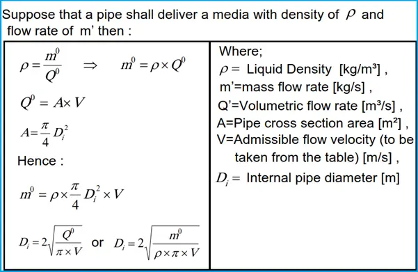
Pipe sizing calculation
After the calculation of the pipe inside diameter, according to the pipe schedule and pipe dimension standard, the suitable nominal diameter is selected.
Now the actual velocity of the medium in the pipe shall be calculated according to the selected nominal diameter.
Note: The metal pipe dimensions are basically according to ANSI B36.10 or API 5L. Also, for the PE pipe please refer to DIN 8074.
Steady Single Phase Compressible Flow in Piping
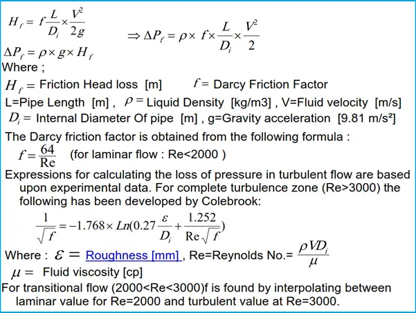
According to Darcy formula, the friction head loss in an incompressible fluid is calculated from the following formula:
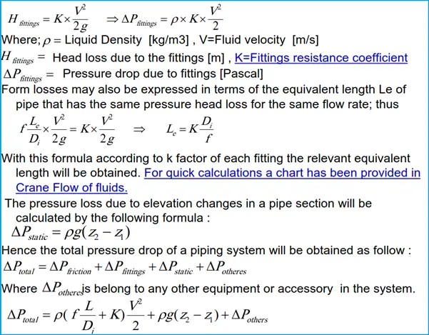
Pressure losses that occur in piping systems due to bends, elbows, joints, valves, and so forth are called form losses. For the recommended values of local flow resistance coefficients (K-factors) please refer to Crane Flow of Fluids.
Sequence of simulation
-Prepare a pipe route (single line) according to the technical specification and system requirements.
-Specify the process characteristics of flow in I/O points (Regarding the Terminal point data, consumers, and system component specifications)
-Specify each pipe section and its node numbers and extract its relevant information from the pipe route and technical specifications (length of the pipe section, its start & end nodes identification, its fitting, fixed pressure drops,…).
-Calculate the pipe size of each pipe section.
-Calculate the total pressure drop in each pipe section. It is noted that the output pressure of each pipe section shall be used as the input pressure of the next pipe section. The total pressure drop is the difference between the inlet pressure pipe section and the outlet pressure of the farthest pipe section.
Checklist for Piping Stress Analysis using Caesar II
In most organizations, there is a 3-tier checking process for every stress system for maintaining the quality of analyzed stress systems. Normally stress system is performed by one (junior or senior), checked by some other (must be experienced enough), and finally approved by the lead stress engineer. Even though the main points which need to be considered are well-known to every piping stress engineer, but still some important points could be missed at specific moments during stress analysis or checking. So a piping stress analysis checklist can be prepared and referred during the process for proper quality control.
The following article will provide insight into the main points that a stress engineer must check during analyzing a system. We request you to inform us of the additional points that We may have missed while writing this article by replying in the comments section.
Important points to consider while checking any stress system (Piping Stress Analysis Checklist Points)
1. Whether the input for pipe material, pipe diameter, pipeline/pipe wall thickness, pipe temperatures (operating, design, and upset), pressures (design and hydro test), insulation thickness, corrosion allowance, fluid density, insulation density is correct?
2. Whether the input for the above design parameters for equipment and nozzles are correct?
3. Whether SIFs for Tee, bend/elbow, cross, and trunnions are taken correctly?
4. Whether the flanged elbow is considered where required?
5. Whether the actual weight of control valves/nonstandard rigid items/valve actuators are considered appropriate?
6. Whether equipment been modeled with the correct dimensions from the general arrangement drawing?
7. Whether trunnion modeling is done following in-house work instructions?
8. Whether settlements/displacements have been considered where required? Normally settlement is used for storage tanks and thermal displacements are used for compressors, turbines, and packaged items.
10. Whether friction has been included when significant?
11. Whether the expansion stress range has been checked in between maximum and minimum temperatures to which the piping system will be subjected?
12. Whether the effect of friction on sliding support loads been considered?
13. Whether the use of low friction pads been properly marked if used?
14. Whether the analysis is performed for the system with and without friction to check the effect of friction (to determine the worst case) as friction is not something that can be relied on? The harmful effects of friction need to be considered but not the benefits.
15. Whether the Caesar plot and isometric plot are matching with the 3D plot?
16. Whether the loads on connected equipment are within the allowable limits?
17. Whether the thermal effects of pipe supports and equipment support been considered?
18. Whether the flange weight includes the weight of bolting? In large-size piping bolt weights become significant.
19. Whether all possible load cases (startup, shutdown, regeneration, any special process consideration) are considered in the analysis?
20. Whether the proper ambient temperature is used for the location?
21. Whether spring is modeled properly and selected considering all operating temperature cases?
22. Whether adequate documentation in case of gapped restraints (or any special consideration) are mentioned in isometric clearly to assure that supports will be installed in that manner on the construction site?
23. Whether there is a possibility of elastic follow-up or strain concentration condition?
24. Whether radial thermal expansion has been considered for line sizes greater than 24 inch NB?
42. Whether PSV forces are considered for open-discharge PSV systems?
43. Whether Hot-Cold and Operating-Standby philosophy has been used when required?
44. Whether restrained and unrestrained piping is defined correctly for pipeline systems (ASME code B31.4/B31.8).
45. If three-way support is provided near the tie-in point, then civil load information for that support considered the impact of another side as well.
46. For Interfacing with other EPC contractors/Package equipment vendors/GRP Vendors data at tie-in points are transferred and back up kept for future reference.
47. For power plants Steam blowing activity is checked with the client and supports are designed for that activity.
48. Reference to FIV/AIV study is clearly mentioned in the Stress report.
49. Whether intermediate nodes are included for dynamic analysis.
50. Supports uplift force for Hold Down Supports are checked and highlighted.
51. Proper supporting for two-phase/slug/surge/vibrating forces is added.
Reactor piping is very critical due to the high temperature and pressure of the fluids it carries. Reactors are used in the process units to contain catalysts. It promotes the chemical transformation of feeds or to remove undesired materials from the feed. They are generally cylindrical in shape, with hemispherical heads and axis vertical to the grade. Spherical reactors are used in methanol and catalytic reforming units. Catalysts are used to promote all chemical reactions taking place inside the reactor.
Principle of Operation of Reactors
Feed enters the reactor at the top. Catalysts are packed along the length of the reactor. As the feed travels down the reactor it is converted into the desired product. The catalysts promote the chemical reaction. The desired product is removed from the bottom of the reactor.
Catalysts in Reactor
Catalysts are generally ball or pellet-shaped and come in a variety of sizes depending on the process requirements. Catalysts tend to get saturated after a while and their efficiency decreases. They need to be regenerated. Catalysts need to be replaced after they get poisoned as they cannot be regenerated.
Reactor Internals
The Internals of reactors is very limited. These include Catalyst bed supports, screens, inlet baffles, outlet collectors, and temperature probes.
Piping Design considerations for Reactors
Locating the Reactor
The piping designer should economize the piping interconnections between the reactor and its adjacent equipment (pumps, feed exchangers, heaters, etc.) when locating the reactor. The following documents are needed to locate the reactor on the plot plan.
The reactor is located on the plot plan as per the process sequence dictated by the P&ID. Reactors are best located on either side of the pipe rack, as close as possible to the heater as dictated by safety and layout guidelines. This is to minimize the costs of the high-temperature piping. Adequate space must be available for operator movement, maintenance access, and catalyst loading and unloading. Reactor transportation, erection, and other constructability issues should also be investigated while finalizing the location on the plot plan. Locating close to an access road reduces maintenance efforts.
After the reactor has been located on the plot plan, the following jobs are carried out.
Reactor elevation calculation and support selection
The Bottom Tan Line elevation is fixed by the following two requirements.
Catalyst unloading requirements – Catalyst unloading is accomplished by a nozzle at the bottom head, inclined to the tan line at a specified angle, and radial to the head. Sufficient clearance should be available for the movement of a catalyst removal truck under this nozzle.
Outlet nozzle – This nozzle is at the bottom of the hemispherical head, and the centerline elevation of the nozzle is lowered accordingly. This becomes a deciding factor in calculating the clear space required between the bottom of the outlet piping and HPP. Springs below the outlet piping should be considered before setting the final elevation.
Reactor supporting arrangement
Reactors are generally supported by the following methods
Skirt Supported with a foundation on grade – most preferred. Skirts are straight for short reactors and flared for tall ones.
Lug supported – Lugs on the reactor supported on concrete piers.
Ring girder supported – On tabletop (when the bottom nozzle needs to be accessed)
Skirt supported – On a tabletop
The choice of support may fix the reactor elevation for some layouts.
Reactor Nozzle orientation
The following documents are required for orienting the nozzles.
Process vessel sketch
Level co-ordination diagram
P&ID
Plant layout specification
Nozzle summary
Insulation requirements
Plot plan
General considerations for locating nozzles
Generally, the following nozzles are present on all reactors.
Inlet nozzle
Outlet nozzle
Catalyst removal nozzle
Instrument nozzle (Thermowell)
Sampling nozzle
Access Manhole
Orienting the nozzles
While orienting these nozzles the following points are to be considered.
The feed inlet is on the top of the hemispherical head. Maintenance access on the top of the head can be separated or combined with the feed inlet, a gooseneck spool serving both purposes.
The outlet nozzle will be on the bottom head, and on the center of the hemispherical head. This is of gooseneck type for vessels with skirt-type support and the nozzle flange must be brought outside the skirt. Orientation is generally chosen to minimize piping to the downstream equipment keeping the line flexible enough from a stress point of view.
The catalyst removal nozzle is to be oriented toward the allocated catalyst drop-down area.
Thermowell nozzles require special consideration with regard to the pull-out area required for the thermowell element. Nozzles are either mounted radially hillside or on the top head of the reactor. A platform is a must at these nozzles.
The sampling nozzle is to be oriented towards an accessible area.
Skin thermocouples are equally placed all around the circumference of the reactor and along the length of the reactor. They should be oriented last, clearing all obstructions.
Nozzle standouts
The feed nozzle on the top of the reactor should have its flange a minimum of 180mm and a maximum of 1000mm from the TOG of the access platform. Consideration for access to nuts under the flange is the be given while calculating the standout. Nozzles on the shell are to have minimum standout that clears the studs from reactor insulation. Reactors are thick shell
Preparing the Nozzle Orientation Document
This document should show the plan, and if required, the elevation of the vessel with the location of nozzles on the same. Nozzle orientation is to be from the plant north and taken clockwise. Dimensioning should show the radial distance of the vessel flange from the vessel center. A nozzle summary table indicating the Nozzle number, service, size, rating, flange face, elevation from the bottom tan line, and stand out from the vessel center is to be included in the drawing. For nozzles on the vessel heads, the F/F stand out from the bottom or top tan line should be given in lieu of elevation from the bottom tan line.
Miscellaneous Data to be included in Nozzle Orientation Document
Lifting Lugs
Generally, reactors can be lifted with two lugs welded below the top tan line. A tailing lug is to be provided near the bottom of the skirt for tailing operation. The preferred locations should be marked on the nozzle orientation drawing.
Earthing Lugs
Two earthing lugs, ideally 180 degrees apart should be provided on the lower portion of the skirt. The same should be marked on the nozzle orientation drawing.
Name Plate
The nameplate should be located at a prominent location and marked on the nozzle orientation drawing. Care should be taken that the nameplate projects outside the vessel insulation.
Vessel Insulation Clips
Indicate that insulation clips/rods are required for holding the vessel insulating bands.
Platforms and Access Ladders
Platforms are required for the following purposes
Operational access to valves and instruments, etc.
Maintenance access to manholes for catalyst loading
Mid landings (when the elevation difference between two platforms exceeds 9 m)
Calculating the TOG elevation
The platform on the top head of the reactor TOG elevation from the top of the reactor head = Insulation thickness + 50 mm clearance + Platform member depth (assume 200 mm minimum) + 30 mm grating. Round off to the next higher multiple of 10.
Platforms on the cylindrical portion of the reactor
Platforms are to be made independent of the reactor in some cases. An Independent structure around the reactor is to be provided at the required elevations.
Nozzles – Platform to be 500mm (minimum) below the bottom of the flange of any nozzle.
Mid landing platforms-These are to be provided when the elevation difference between two platforms levels exceeds 9m. The mid landing to be ideally evenly placed between the two platforms.
Two platforms being serviced by a single ladder should ideally have an elevation difference of 600mm between them.
The platform elevations (TOG) should be rounded off to the nearest multiple of 10.
Sizing the Platform of the Reactor
The platform on the top head of the reactor
This platform should be rectangular. It should cover all the nozzles, flanged piping joints, valves, instruments, davits, etc. that need access for operations and maintenance. Ideally, a minimum space of 750mm should be provided around 3 sides of a nozzle. Side entry access to the platform should be the first preference.
Platforms on the cylindrical portion of the reactor
This platform should be rectangular. Its extent should cover all the nozzles, instruments, etc. that need access for operations and maintenance.
Determining the platform width
The inner radius of the platform should clear the reactor insulation by 50 mm.
Platform width is dictated by operator access requirements.
The following considerations are to be taken care of when deciding the width.
The platform should extend along the thermowell element removal area.
A free landing space of 750 mm is to be provided for access ladders.
Platforms may be locally extended width-wise at regions where vertical pipes pierce the platform, maintaining a minimum of 750 mm clear space from the insulation of piping to the handrail of the platform.
When controls are located on the platform, the width of the platform is to be 900 mm plus the width of the controls.
Access ladder
Access ladders are to be vertical. They should have a clear climbing space of 680 mm. Toe clearance from the centerline of the ladder rung to any obstruction to be 230 mm.
A cage is to be provided for all ladders at an elevation of 2300 mm and above. Side entry ladders are the first preference.
The ladder is to be oriented so that it can also be utilized for access to instrument connections that are inaccessible from the working level.
Preparing the Platform Input Document
Platform and Access ladder input is transmitted to Civil via a platform input drawing.
The platform on the top head of the reactor:
This should clearly indicate the TOG elevation from bottom T/L, dimensions of the platform, and its location w.r.t. the vessel center lines. Grating cutout requirements (indicating size, shape, and location), required swing direction of the self-closing gate, and davit location needs to be marked on the same drawing. Any pipe supports/monorails intended to be taken from the platform should be marked.
Platforms on the cylindrical portion of the reactor
This should clearly indicate the TOG elevation from bottom T/L, the dimensions of the platform, and its inner radius from the vessel axis. Grating cutout requirements (indicating size, shape, and orientation), required the swing direction of the self-closing gate. Any pipe supports/monorails intended to be taken from the platform should be marked. Orientations of access ladders should be marked on the respective platform elevation plans.
Orienting piping on the face of the reactor
It is imperative that the orientations, arrangement, and standouts of various piping traveling down the face of the reactor are calculated keeping in mind the following points.
Piping should drop towards the pipe rack side, clear from any platforms.
The piping can travel down the reactor radially, with independent supports.
The clear minimum space between the pipe and shell is to be 300 mm excluding any insulation.
The pipe with insulation should clear the stiffening ring and its insulation.
The minimum orientation angle between two adjacent pipes should be calculated to clear the support bracket of one pipe hitting the insulation cladding of the adjacent pipe.
Support points of adjacent piping should be offset to save space between them. as the support brackets will have to be oriented so that there is no clash between the cleats of the supports, or between the support members and bracings.
Supporting Piping from Reactors
Piping should be supported from the vessel or its platform when it is difficult to construct civil support from grade or adjacent structures at the required location. Vessel support should also be taken to take advantage of lower differential thermal growth between vessel and piping, as compared to piping and civil support. A judicious selection of support locations can eliminate the requirement for springs.
Thumb rules for supporting piping from reactors
Small loads can be transferred directly to the platform members. These include rest, one-way stops, two ways stop, or hold-down supports and the piping layout should be done accordingly.
Large loads should be transferred to the vessel shell and the piping layout should be done such that the platform members do not interfere with these independent supports.
The first piping support is rest support and it should be as close to the equipment nozzle as possible. The second and subsequent supports are guides and they are to be located as per the allowable piping spans available in the tables. For tall reactors, another rest support may be needed. This is done by providing spring support which will take care of the differential expansion of the vessel and piping.
Piping support should not cause any hindrance to the movement of personnel.
Vessel growth should be considered to check the clash of piping support with any adjacent piping or structure.
Types of supports
Supports welded to piping
Horizontal trunnions welded to the pipe take the vertical load of the pipe. They are generally used in pairs, set apart at 180°. Their axis is perpendicular to the line drawn from the center of the reactor to the center of the pipe at the location of support. Trunnion lengths should be adequate so that their ends project 50mm from the outer edge of the support bracket member Shoes are provided for guidance purposes and to prevent insulation cladding from hitting the support bracket member. Adequate shoe length is to be taken for differential movement of pipe and vessel.
Supports welded to the vessel
Support brackets (non-braced and braced) and Guide brackets (non-braced and braced) are the most common support arrangements for vertical piping.
Calculating the minimum dimensions of support members
Load bearing supports
Trunnions or springs transfer load to these supports. Minimum clear inside dimensions are calculated so that the insulation cladding is 50 mm away from the inside of the structural member or support plate of the spring.
Guide supports
A bare pipe is guided directly by the guide bracket. Shoes are provided in pairs, 180° apart, for lines with insulation. These can be single pairs or double pairs depending upon the type of guiding required at that location. The guide gap required by stress is to be added to the end-to-end dimensions of the bare pipe or pipe with shoes.
Preparing the Civil Pipe Support (CPS) Input Document
CPS input is transmitted to Civil and Mechanical via a CPS input drawing. A sketch clearly indicating the TOS, dimensions, and CPS location with respect to the vessel centerline needs to be drawn. Any requirement for additional support plates for springs or trunnions is to be indicated. A summary table indicating the CPS number, TOS, stress file number, and corresponding node number from the Nozzle cleat load information chart needs to be created. The Nozzle cleat load information chart indicates the various loads acting at the support location under various conditions. It is to be attached along with the CPS input document.
What is a Sour Service? | NACE Sour Service Criteria
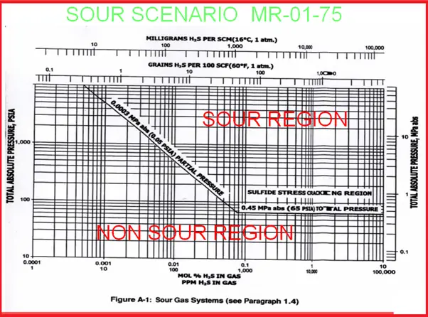
Sour Scenario in the oil industry as per NACE MR-01-75
Refer to the below image (Fig. 1) which shows a curve segregating the sour and non-sour regions as per NACE MR-01-75. The curve denotes the amount of H2S requirement for qualification of being Sour at a given absolute pressure.
Fig. 1: Sour Scenario as per MR-01-75
Limitations of NACE MR-01-75
Saltwater wells, injection wells
Downstream Industries, Petrochemical
Refineries and Chemical plants
Low-pressure multiphase systems
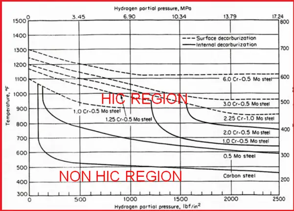
HIC Scenario – API Nelson Curves
Refer to Fig. 2 which shows the HIC and Non-HIC regions.
Fig. 2: HIC SCENARIO – API NELSON CURVES
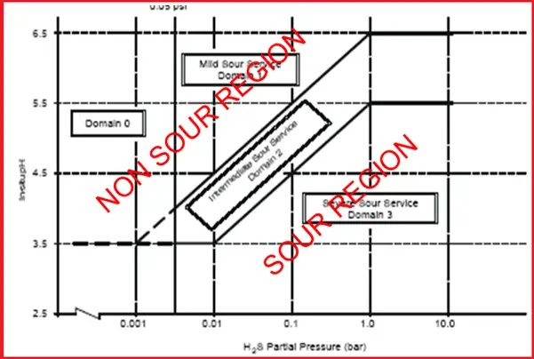
Sour Scenario as per ISO 15156 / EFC 16
Fig. 3 shows the sour service criteria as per ISO 15156/EFC 16.
Fig. 3: SOUR SCENARIO – ISO 15156 / EFC 16
Sour Service H2S ppm Criteria as per DEP
Shell DEP provides the following H2S criteria for fluid services
As the name implies, plastic pipes are made of plastic materials. Due to its many advantages, plastic pipes are the ideal choice in many piping and plumbing solutions. In fighting corrosion, plastic pipes are an important alternative.
Corrosion (deterioration of materials under the influence of an environment) is a big problem in all operating Process Plants. Many of the failures reported in Plants are because of Corrosion. Hence given a choice one would be tempted to dispense away with Steel altogether as a material of construction for piping used. Unfortunately, it is not practical to undermine the usefulness of Steel in sustaining the Pressure and Temperature conditions normally foreseen in any Process Plant. That brings the concept of composite piping constructed from highly Chemical Resistant Polymer Compounds as the base material, reinforced with suitable fibrous materials such as Glass which provides it the requisite strength.
Advantages of Plastic Pipes
Plastic piping offers various advantages as listed below:
Economic.
Easy Installation.
an ideal choice for low-temperature services.
Lightweight, and easy to handle.
Low Support load.
Rust and corrosion-resistant.
Smooth surface so less frictional loss.
Chemical resistant.
Applications of Plastic Pipes
Due to its inherent benefits, Plastic pipes are widely used in the water and food industry for transferring drinking water, wastewater, irrigation, chilled water systems, chemicals, heating fluid, cooling fluids, foodstuffs, etc.
Types of Plastic Piping
Depending on plastic piping materials, basically, 3 types of Synthetic Polymer Components have found acceptance in industrial use.
Thermoplastic piping
Thermosets and
Composite Plastic piping
Thermoplastic Piping Materials
The Thermoplastics are Polymer Compounds, which are normally available in crystal form. On the application of heat and pressure, these crystals attain the requisite level of flowability to be able to attain the desired shape by a molding process. On re-heating, the plastic material can once again undergo the transformation from solid to a flowable state which allows their reprocessing into the desired shape.
Some of the commonly used Thermoplastic materials are as follows:
By and large, thermoplastics are structurally weak materials and have limited temperature endurance.
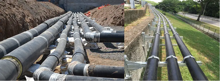
Fig. 1: Typical HDPE Piping System
Thermoset Piping Materials
Thermosetting Plastics are Polymer compounds (resins), which are normally available in liquid form at ambient temperature. With the addition of a Catalyst and an Accelerator, these Resins undergo a chemical transformation into a rigid product that sets into the required shape by the curing process.
Some of the commonly used Thermosetting Plastics are as follows:
Epoxies
Furans
Phenolic
Polyesters – Bisphenol, Isophthalic, Halogenated
Polyurethane
Vinyl esters
Even though Thermosetting Plastics are relatively superior to Thermoplastics in terms of structural strength and temperature endurance, still in their virgin form they find limited use in industrial applications.
Composite Plastic Piping Materials
It is evident from the foregoing discussion that both Thermoplastics and Thermosetting Plastics in their virgin form lack the ability to sustain the level of mechanical loading normally encountered in Industrial applications. An attempt to strike an appropriate balance between the two desired properties of the material (i.e. Mechanical Strength and Corrosion Resistance) therefore has always remained a desirable objective. This brought forward the concept of Composite Plastics wherein a reasonable degree of mechanical strength is imparted to the base Polymer which in itself is adequately resistant to Chemical Corrosion, by way of reinforcing it with a suitable reinforcing material.
Most of the commercially available composite materials in the Reinforced Plastic category use a combination of Thermosetting Plastic Resins (e.g. Polyester, Epoxy, Vinyl Ester, etc.) and Fiberglass or Synthetic Fibres as reinforcing material. In order to provide ultra-superior chemical resistance, it is also possible to manufacture a composite material using Thermoplastic Material (e.g. PVC, PVDF, PP, etc.) as a baseliner over which the layers of Thermosetting Resins and Fiberglass are applied to attain the required mechanical strength.
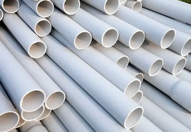
Fig. 2: Typical PVC Pipes
Composite plastic Piping Manufacturing Process
Composite plastics pipes are commonly produced by one of the following methods:
Custom Contact molding
It is a manual/ semi-automated process in which the composite sections are manufactured by application of various layers of resin and Glass Fibers (in various forms such as surface mat, roving mat, chop-strand mat, etc.) either by Hand Lay-up or by Spray Lay-up method.
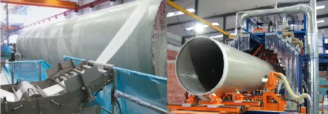
Filament Winding
It is a fully automatic process in which automatic control over winding angle ( 0 to 90 degrees) and winding pressure can be exercised to obtain the varying degree of Hoop – Axial ratio and Glass – Resin percentage composition. Normally a winding angle of 54 3/ 4 Degrees provides a 2:1 Hoop–Axial ratio which is a condition of optimum internal pressure requirement. By increasing the winding pressure the Glass – Resin proportion could be varied from 80 % – 20 % to 60% – 40 %. A composite section of high Glass content will result in high strength and low chemical resistance and vice versa.
Fig. 3: Filament Winding Process
Pultrusion
As the name implies this is a sort of extrusion process by pulling the filaments through a resin bathtub and subsequently passing it through an extruding die and then through an atmosphere of controlled elevated temperature. The above process is commonly used for manufacturing rolled sections such as Angles, Channels, I Beams, etc.
Resin Transfer Molding
The above process is used for specialized applications for the manufacture of sandwich structures with certain core materials.
Plastic Piping System Design Considerations
The Plastic Piping System consists of Piping Profile fabricated from plain end pipe, plain and flanged end Fittings (i.e. Elbows and Reducers), and stub-in branch connections. The Flanged Joints are Stub Ends with loose Backing Flanges. In the case of Flanged Tapping Long Stub Flanges are recommended to be used in place of pipe stub-in and Short Stub Flanges. The pipe-to-pipe and pipe-to-fittings joints are laminated joints. Accessories for Piping System include Soft Rubber/ CAF Gaskets and Full Threaded Fasteners with Washers. The major considerations for the plastic piping system are listed below:
1. Owing to weak mechanical properties a minimum of NS 2” line size is recommended for Plastic Piping. However, tapping of small size (i.e. smaller than NS 2”) is permitted for drain/ vent, etc. provided the branch connection is adequately supported.
2. Owing to its large Coefficient of Thermal Expansion Plastic Pipelines exhibit a high tendency to grow under moderate temperatures. This may result in a sizable deflection of the branches and the corners of the Piping Profile. It shall, therefore, be ensured that the branch connections are not overstressed, either by providing adequate flexibility on the branch piping or by fixing the branch points by external means to disallow its deflection.
3. If free movement of the corners of the piping profile can be allowed (i.e. e.g. not being hindered by any other external item) then it is preferable to leave the profile to grow freely. However, if the growth of the profile has any adverse effect on the system stability (e.g. supports falling off from the external structure) it may be appropriate to restrict the growth of the sides of the profile by providing fixed supports at various locations as per Plastic Piping Support recommendations.
4. Unlike Steel, bellows are not used on Plastic Piping. The thermal stress behavior is addressed either by providing in-built flexibility in the system or by arresting the axial growth of the pipe runs within the pipe length itself. In case the later method is employed, the pipe may have to be guided at close intervals to avoid failure due to buckling.
5. Owing to its weak nature, the plastic piping shall not be supported by line contact between the pipe surface and the external structure taking the load. Hence as a general rule Clamp and Shoe type supports shall be employed on Plastic Piping System.
6. All concentrated loads (e.g. On-line Valves, Instruments, etc.) shall be directly supported to ensure that the load is transferred to the grade/ external structure without stressing the piping.
7. All the valves employed on Plastic Piping shall be provided a Fixed Type Support to ensure that the Piping is not overstressed in case of jamming of the Valve handwheel while operating.
8. Due to the excess thickness of the Plastic Pipe (as compared to Steel) it is likely to obstruct the opening of the flap of the Sandwich type Butterfly/ Wafer Check Valve into the pipe. In order to address the above issue, the Spacer Rings (made of the same or equivalent material as a pipe) will be employed across the valve. The above Spacer Ring is procured as a Special Part.
9. The Plastic Piping System shall be installed with permanent supports in place. The erection of Plastic Piping with temporary supports is not acceptable.
10. The pipes shall not be stretched in order to match the terminal ends
11. The Flange Joints shall be tightened to the specified Torque Value only by employing Torque Wrench.
12. As far as possible the Piping profile shall be prefabricated in the Vendors shop at the site, leaving only a few field joints for final fit-up.
13. In the case of FRP Piping with Thermoplastic Liner, the Field Weld will always be located at the convenient height/ location to allow down-hand welding/ jointing.