A Piping Snubber is a Dynamic Restraint that protects the piping system against impulse loading conditions from Seismic or Surge Events. It is basically a mechanical device that allows pipe operating displacement but restricts the sudden movement of dynamic events.
“Static” snubbers have a support restraint called SNB following a translational direction in the restraint type field. When a snubber is entered, the restraint fields in Ceasar II change as follows: Gap and Mu are disabled.
Snubbers are the translational restraints that provide resistance to displacement in static analysis of occasional loads only. It is assumed that occasional loading is dynamic in nature, similar to static seismic or static wind loading.
THESE SNUBBERS ARE INACTIVE FOR ALL EXPANSION SUSTAINED, AND OPERATING STATIC CASES, AND ARE ACTIVE FOR ALL TYPES OF TRUE DYNAMIC ANALYSES, i.e. HARMONIC, MODAL, OR SPECTRAL.
These restraints will be active in all static load cases defined as occasional in the load case list. Static snubbers may be directional, i.e. may be preceded by a minus or plus sign.
Steps for Snubber Modeling
The steps for modeling Snubber are mentioned below:
Create a node where snubber is required to add. (Node 10)
Run the operating cases without defining a snubber at that node.
Note the displacement in all six degrees of freedom at the location (Node 10) where to add the snubbers (Assume D1 is the displacement at that node at T1 temp and D2 at T2 temp).
From input, the piping spreadsheet clicks on the restraint checkbox and defines XSNB/ZSNB, etc as per requirement at node 10 with a distinct C-Node 11. It will appear as a guide in Caesar Sketch.
Place displacements on the CNode (CNode 11) by activating the displacement checkbox.
Modify the load cases by including D1 everywhere T1 displays and D2 where T2 appears for Operating load cases.
For defining occasional stresses create the following load cases as given in Fig. 1.
Run the analysis to obtain results.
Fig. 1: Load Cases for systems having a Snubber.
Application of Snubber
Snubbers are normally used for reducing the damaging effects of earthquakes, turbine trips, relief valve discharges, and surge events.
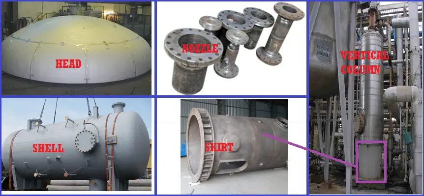
Pressure Vessels are one of the most important Static or stationary equipment for any process plant. We can not think about any chemical plants or Refineries or Petrochemical complex which runs Without any Pressure Vessel. Major chemical processes happen inside pressure vessels. These may be vertical or horizontal and are known by various names like column, drum, reactor, exchanger, etc. They can carry or process fluids of various temperatures and pressure ranges. Most of the time these are designed following the ASME BPVC code. In this article, major component vessel parts will be explained in brief.
Head (Fig. 1): The end enclosures of a vessel. They can be
semi-elliptical, spherical, or dished.
Shell (Fig. 1): The cylindrical walls of a vessel. Sometimes shells
can be insulated depending on body temperature or process conditions
Pressure Vessel Nozzle (Fig. 1): The tie-in connection between the vessel or equipment and the piping system. Nozzles are provided in locations where a commodity is either introduced or removed from a vessel or piece of equipment.
Nozzle orientation: The angular arrangement of nozzles around the perimeter of a vessel’s shell.
Nozzle projection: Used to establish the distance from the vessel’s centerline to the nozzle’s face of the flange.
Fig. 1: Typical Vessel Parts
Base plate: A flat, metal ring welded to the bottom of a vessel’s
supporting skirt that rests on a concrete foundation. Holes around the
perimeter of the metal ring make it possible to position it over anchor bolts
and secure it to the foundation.
Skirt (Fig. 1): A cylinder-shaped support for a vertical vessel. One end is welded to the base plate allowing it to rest on the foundation and the other end is welded to the bottom head of a vertical vessel.
Skirt access opening: An 18’’ ID hole 2’-6’’ above the foundation
that allows workers entrance for inspection and maintenance.
Skirt vents: Equally spaced holes approximately 3 to 4 in diameter bored near the top of the vessel skirt that allows toxic and explosive gases to escape.
Skirt fireproofing: Generally brick or granite, fireproofing is applied around the interior and exterior walls of a vessel skirt. It is necessary to prevent damage to the vessel skirt in case a fire occurs.
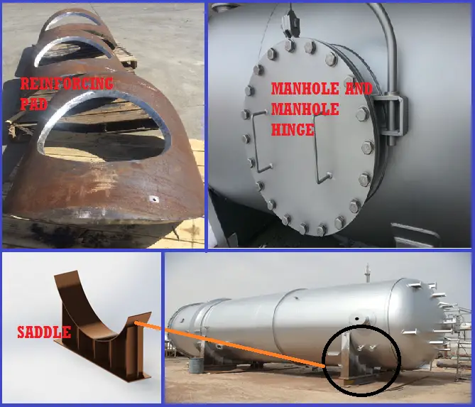
Reinforcing pad (Fig. 2): A plate contoured to the shape of a vessel shell. It is positioned around nozzles and provides additional strength in the areas where metal was removed from the shell.
Manholes (Fig. 2): Similar to large nozzles that allow workers entry points into a vessel. They generally are 18 IDs and are accessible by ladders and platforms. When not in use, the manhole is sealed with a blind flange.
Manhole hinge (Fig.
2): A hinge that creates a pivot point allowing the blind flange attached
to the manhole to be easily removed for worker entrance.
Seal pan: A tray installed below the bottom tray in a vessel to prevent liquids from bypassing the trays.
Fig. 2: Typical Saddle, Manhole, and reinforcing PAD
Trays: Flat metal plates spaced approximately 18 to 24 apart inside a vertical vessel. They can be bolted or welded to the vessel shell. Trays are perforated to allow rising vapors and falling liquids to pass through with the aid of a valving mechanism called a cap.
Weir: A dam-like
plate welded on a tray that allows a fractionated by-product to collect and be
extracted by a nozzle.
Downcomers: Openings adjacent to a tray that allows liquids flowing over a weir plate to fall to the tray below and begin the fractionation process over again.
Insulation rings: Continuous circular rings welded to the exterior of a vertical vessel that supports a vessel’s insulation. They are typically spaced on 12–0 centers.
Saddles (Fig. 2): U-shaped supports welded on horizontal vessels and exchangers. Saddles are bolted to concrete foundations and create cradle-like support in which the vessel can rest.
Lifting lugs: donut-shaped rings welded to the vessel’s shell or head that allow the vessel to be raised and positioned during installation.
This article is prepared by Mr. Satish Atmanathan, a senior oil and gas professional with extensive work experience. For a more detailed explanation of all the above parts and visualization, listen directly to him in the following video:
Vessel Parts Explained Video
Online Course on Pressure Vessels
If you wish to learn more about Pressure Vessels, their design, fabrication, installation, etc in depth, then the following online courses will surely help you:
Process Flow Diagram or PFD and P&ID or Piping/Process & Instrumentation Diagram are chemical/process engineering drawings and are very important for Process, Piping, Mechanical, and Instrument Engineers and Designers of any Process Plant or Power Plants. These drawings are very useful as they convey the right amount of process information as needed during various stages of bidding, engineering design, procurement, construction, operating & commissioning phases of the process.
What is a Process Flow Diagram or PFD?
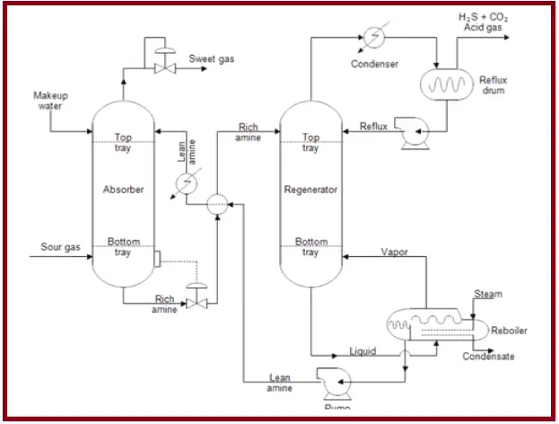
A Process Flow Diagram (PFD) shows the relationships between the major components in the system. Generally, a PFD (Fig. 1) shows only the major equipment and doesn’t show details. A PFD does not show minor components, piping systems, piping ratings, and designations. This diagram shows the flow of chemical fluids and the equipment involved in the process with the properties of flowing chemical fluids (like temperature, pressure, fluid density, flow rate, etc).
Process engineers are responsible for designing PFD based on the chemical process and thermodynamic properties of the fluid in question. Typically, process flow diagrams of a single unit process will include process piping, major equipment items, control valves, and other major valves, connections with other systems, major bypass and recirculation streams, operational data (temperature, pressure, mass flow rate, density, etc.)
Fig. 1: Sample PFD
Process flow diagrams generally do not include minor components like process control instrumentation, piping systems like control loops, by-pass lines, drain lines, pipe properties like size, specification, ratings, pipe classes, pipeline numbers, components such as isolation and shut-off valves, maintenance vents and drains, relief, and safety valves, vents and drain.
What is the Piping/Process & Instrumentation Diagram (P&ID)?
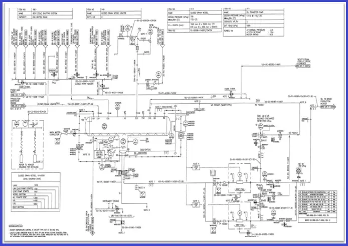
A Piping and Instrument Drawing (P&ID– Also known as PEFS, Process Engineering Flow Scheme in some engineering organizations) includes more details than a PFD. It includes both major and minor details of the chemical process. P&ID (Fig. 2) shows all major equipment, piping details like service, size, spec, rating, insulation, etc, instrumentation details like pressure, temperature, and flow instruments, control valves, pressure safety valves, meters, pipe routing information such as slope, tapping, free flow.
Instrumentation and their details are shown using standard symbols which vary from company to company.
All kinds of valves used like On-off valves, motorized valves, relief valves, and miscellaneous items like strainers, vents, drains, silencers, standpipes, etc. are shown in the P&ID.
Fig. 2: Sample P&ID
Vendor items and packages are shown with their limits and interfaces. A lot of information such as equipment design pressure, temperature, and material of construction, free-draining requirements is provided as notes in the P&ID.
Line numbers, Tag numbers, and Equipment Numbers shown in the P&ID are usually retained in the further documents and drawings created.
P&ID includes:
Mechanical equipment with names and numbers
Pipeline number, size, material, insulation
Every instrument and its pneumatic/ electric signal
Miscellaneous – vents, drains, special fittings, sampling lines, reducers.
A P&ID does not include:
Equipment rating or capacity
Instrument root valves
Manual switches and indicating lights
Primary instrument tubing and valves
Elbows and similar standard fittings
Extensive explanatory notes
In both, PFD and P&ID arrows indicate the flow of materials. Normally P&IDs are a more detailed scheme of simple PFDs.
About The Author: This article is written by Mr. Khaja Najmuddin, a Piping Stress Engineer with extensive experience in the Oil and Gas sector. For more details about the author click here to refer to his LinkedIn profile.
Pipe Support Friction Coefficient and Frictional Loads on Pipe Supports
Pipe Support friction plays a significant role in pipe stress analysis. All piping stress engineers must be aware that while modeling supports or restraints we have to enter the frictional coefficients at the pipe support surfaces. The value of this coefficient depends on the supporting surface material and surface roughness. During the project bidding stage (ITB Document) the client generally provides the information regarding which friction factor to be used for which surface.
Also, every EPC organization prepares its own guideline for using standard friction factors in case not available in the ITB document. The following write-up will try to provide an idea regarding which coefficient of friction to be used in what situation. This can be used as a guide only. However, project-specific data or information will override any word mentioned here.
What is Friction Coefficient?
The coefficient of friction provides a measure of the amount of friction existing between two sliding surfaces. The coefficient of friction is defined as the ratio of the Normal force to the resisting force. As the friction coefficient is a ratio of two forces, it is a unit less or non-dimensional.
Coefficient of Friction for Various Surfaces
The coefficient of friction factor depending upon the supporting interface (i.e, the junction between the Top of the Steel and the Bottom of the Pipe or Bottom of the Shoe/Cradle) shall be applied at all vertical restraints (+Y or Y supports) locations as mentioned below. But if ITB for any project provides separate data then those data shall be considered.
Carbon Steel to Carbon Steel: 0.3
Polished Stainless Steel to Polished Stainless Steel/Graphite: 0.15
Pipe on Sand Soil (pipe laying on the sand): µ=0.4
There is various philosophy among EPC companies regarding the use of coefficient of friction for guide and directional anchor supports. Some organizations prefer not to use any frictional co-efficient for horizontal support. However if used the same can be taken from the above table (normally 0.3 is used if no special arrangement is made).
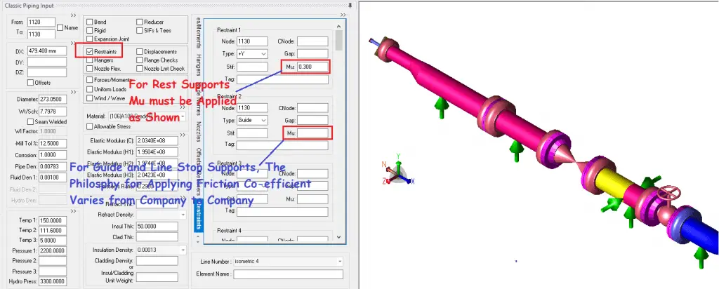
Using Support Friction in Caesar II
Refer to Fig. 1 to understand the Support Friction Co-efficient application philosophy in the Caesar II input screen.
Fig. 1: Support Friction in Caesar II
Friction coefficient must be applied for all vertical sliding restraints or Rest types of supports. However, there is variation in the philosophy of friction coefficient application for guide and line stop supports. Some organizations use the friction coefficient for guide and limit stops, while some organizations do not use it.
Again, there are differences in support friction considerations for occasional stress calculations. Some organizations set the friction multiplier in Caesar II load cases as zero. They believe that occasional events like seismic, wind, slug, etc being dynamic events, the application is quick and friction does not get time to act in those instances. Where some organizations keep the friction multiplier value as 1, so, follow what your organization is following during the aboveground pipe stress analysis.
Significance of Support Friction
As you can see in Fig. 1, In CAESAR II, the friction is activated at any restraint by entering a non-zero Mu value. Generally, no friction factor is used while supporting using rigid hangers.
In general, friction will always be present whenever a pipe moves. The frictional force will act against the pipe’s movement. The maximum frictional force against the pipe sliding will be Mu (Coefficient of friction) times the vertical restraint force. If a pipe movement is in the +X direction, the frictional force will act in the -X direction. Friction creates a non-linear effect on the piping system.
As friction opposes pipe displacement, it will create high stress on the pipe and higher loads on the connecting equipment.
Many a time in Caesar, you may find that due to the non-linear effects, the iteration in Caesar II analysis does not converge. In that situation, deleting the friction from that specific support node can converge the solution, and the result is obtained.
Reducing Pipe Support Friction Forces
To optimize structural design, qualify expansion stresses, and qualify nozzle loads, it may be required to reduce frictional loads. As we know,
Frictional force=Coefficient of Friction (Mu) * Vertical Normal Force at the support location.
As the vertical force is usually constant, the friction force can easily be reduced by changing the friction coefficient.
This is the reason that pipe stress engineers sometimes use SS/PTFE/Graphite plates at the contact surfaces to reduce the friction coefficient, which in turn reduces the horizontal frictional force. Special support design arrangements are made to use PTFE/Graphite/SS plates.
However, some organizations argue that with the passing of time, the reduced friction coefficient does not remain valid, and the friction coefficient increases. Also, there may be the inclusion of sand particles in between the contact surfaces where a frequent sand storm is expected. So, many organizations do not prefer to use PTFE/Graphite slide plates to reduce frictional loads.
Sometimes, pipe roller supports or Spring Hanger Supports are used in place of normal resting supports to reduce support friction.
Some Important Considerations Related to Pipe Support Friction Coefficient
In case when Sliding Plate is required, add the comment “(PTFE/Graphite) Sliding Plate Required” and mention friction factor μ=0.1 /0.15 respectively depending on temperature” on the stress sketch. Use a Teflon (PTFE) Slide plate up to a temperature of 204 degrees Centigrade, above which use a graphite plate (up to 540 degrees Centigrade).
Normally, the friction factor shall not be applied when modeling a bottom-type spring. But sometimes ITB document/Client could insist on friction modeling of bottom type springs, in that situation, the friction factor could be applied as per the requirement.
When the pipe/shoe is supported on the welded rod on the structure, a friction factor of 0.25 shall be considered.
For Compressor and Turbine piping systems, some organizations want to qualify the equipment nozzle loads in both cases, using friction and without friction.
For Zigzag pipelines, it’s preferable to check pipeline displacements without support friction and decide on the sleeper or support dimensions. There are many instances of pipe movement at the support location that are more than the pipeline design displacements, considering support friction. So, designing support dimensions without considering the friction effect solves the problem.
Further Studies on Support Friction in Pipe Stress Analysis
I had already published an article that relates to the most common ferrous materials used in the piping industry. Click here to visit the page. In this article, I will mention the most frequently used non-ferrous piping materials.
In comparison with metallic materials, the use of plastics is limited to relatively moderate temperatures and pressures [230 deg C (450 deg F) is considered high for plastics]. Plastics are also less resistant to mechanical abuse and have high expansion rates, low strengths (thermoplastics), and only fair resistance to solvents. However, they are lightweight, are good thermal and electrical insulators, are easy to fabricate and install and have low friction factors. Since plastics do not corrode in the electrochemical sense, they offer another advantage over metals. The important thermoplastics used commercially are polyethylene, polyvinyl chloride (PVC), fluorocarbons (Teflon, Halar, Kel-F, Kynar), and polypropylene. Important thermosetting plastics are general-purpose polyester glass-reinforced, bisphenol-based polyester glass, epoxy glass, vinyl ester glass, furan, and phenolic glass, and asbestos reinforced. While using non-metallic piping, viz HDPE, PVC, FRP, etc, the designer shall take care of the service, pressure & temperature. The manufacturer’s recommendation shall be taken into account.
Thermoplastic Pipes
The most chemical-resistant plastic commercially available today is tetrafluoroethylene or TFE (Teflon). This thermoplastic is practically unaffected by all alkalies and acids except fluorine and chlorine gas at elevated temperatures and molten metals. It retains its properties up to 260 deg C (500 deg F). Perfluoroalkoxy, or PFA (Teflon), has the general properties and chemical resistance of FEP at a temperature approaching 300 deg C (600 deg F). Polyethylene is the lowest-cost plastic commercially available. Mechanical properties are generally poor, particularly above 50 deg C (120 deg F), and the pipe must be fully supported. Carbon-filled grades are resistant to sunlight and weathering. Polypropylene has a chemical resistance about the same as that of polyethylene, but it can be used at 120 deg C (250 deg F).
Thermosetting plastic Pipes
Among the thermosetting materials are phenolic plastics filled with asbestos, carbon or graphite, glass, and silica. Relatively low cost, good mechanical properties, and chemical resistance (except against strong alkalies) make phenolics popular for chemical equipment. Furan plastics filled with asbestos and glass have much better alkali resistance than phenolic resins. Polyester resins reinforced with fiberglass, have good strength and good chemical resistance except to alkalies. Epoxies reinforced with fiberglass have very high strengths and resistance to heat. The chemical resistance of the epoxy resin is excellent in non-oxidizing and weak acids but not good against strong acids. Alkaline resistance is excellent in weak solutions.
Pipes produced from Rubber and elastomers
Rubber and elastomers are widely used as lining materials. The ability to bond natural rubber to itself and to steel makes it ideal for lining tanks. Natural rubber is resistant to dilute mineral acids, alkalies, and salts, but oxidizing media, oils, and most organic solvents will attack it. Hard rubber is made by adding 25 percent or more sulfur to natural or synthetic rubber and, as such, is both hard and strong. Chloroprene or neoprene rubber is resistant to attack by ozone, sunlight, oils, gasoline, and aromatic or hydrogenated solvents, but is easily permeated by water, thus limiting its use as a tank lining. Nitrile rubber is known for its resistance to oils and solvents. Butyl rubber’s resistance to diluting mineral acids and alkalies is exceptional. Hypalon has outstanding resistance to ozone and oxidizing agents except fuming nitric and sulphuric acids. Fluoroelastomers (Viton-A, Kel-F, Kalrez) combine excellent chemical and temperature resistance.
Medium Alloys
A group of (mostly) proprietary alloys with somewhat better corrosion resistance than stainless steel are called medium alloys. A popular member of this group is 20alloy. Made by a number of companies under various trade names. Durimet 20, and Carpenter 20 are a few names. This alloy was originally developed to fill the need for a material with sulphuric resistance superior to stainless steel. Other members of this group are Incoloy 825 and Hastelloy G-3. These alloys have extensive applications in sulphuric acid systems. Because of their increased nickel and moly contents, they are more tolerant of chloride-ion contamination than standard stainless steel. The nickel content decreases the risk of stress-corrosion cracking and molybdenum improves resistance to crevice corrosion and pitting.
High alloys
The group of materials called high alloys all contain a relatively large percentage of Nickel. Hastelloy B2 contains 61% Nickel & 28% Mo. The alloy has unusually very high resistance to all concentrations of HCL at all temperatures in the absence of oxidizing agents. Other materials of this group are Chlorimet 2 & Hastelloy C-276.
Nickel & Nickel alloy Pipes
The metal is widely used for handling alkalies, particularly in handling and storing caustic soda. Neutral alkaline solutions, seawater, and mild atmospheric conditions do not affect nickel. A large number of nickel-based alloys are commercially available. One of the best known out of these is Monel 400 with 67% Ni and 30 % Copper. This Ni-Cu alloy is ductile and tough. Its corrosion resistance is better than its components, being more resistant than a nickel in reducing environments and more resistant than copper in oxidizing environments.
Pipes from Copper and copper alloys
Copper and its alloys are widely used in chemical processing, particularly when heat and thermal conductivity is very important. The main copper alloys are brasses(Cu-Zn), Bronzes( Cu- Sn), and Cupronickels. Some of the bronzes are very popular in the process industry, like Aluminium and silicon bronzes because they combine good strength with corrosion resistance. Cupronickels have 10-30% nickel and have become very popular because it has the highest corrosion resistance of all copper alloys. This finds its application in heat-exchanger tubing and its resistance to seawater especially outstanding.
Titanium Pipes
Titanium has become increasingly important as a construction material. It is strong and of medium weight. Corrosion resistance is very superior in oxidizing and mild reducing media. Titanium is usually not bothered by impingement attacks, crevice corrosion, and pitting attacks in seawater. Its general resistance to seawater is excellent. A detailed list of commonly used non-ferrous materials in hydrocarbon industries is given in the following table.
Common Non-ferrous Pipe Materials
Static Method of Wind Analysis of Piping systems in Caesar II using Pressure Vs elevation Method
Wind analysis is performed based on the Client/ITB requirement. Wind load is an occasional load that normally occurs less than 20% of plant operating time. There are two methods for wind analysis-Static and Dynamic. In this article, I will explain the static method of wind analysis using Caesar II of Hexagon PPM (COADE Inc) following the Pressure Vs Elevation Profile.
Criteria for the selection of lines for Wind Analysis:
Criteria should be mentioned in the ITB document. As a guideline, the following can be followed after verification from the client:
Lines with outside diameter 10” and larger (including insulation) running on 10 m and above.
Steam / Flare header on the pipe rack.
Other lines are considered important as per the stress engineer’s decision.
However, if lines are covered by some shelter or other structures then wind analysis can be ignored for those lines.
Data Required for Wind Analysis
For wind analysis, you must have the following data from the client.
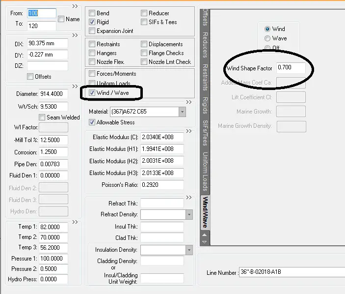
Wind shape factor: Normally for pipe elements, the data varies from 0.6-0.8. Check in the ITB document what value it says to use.
Pressure Vs Elevation Profile: Sometimes the client provides this profile directly and sometimes provides equations and data to calculate the profile. A typical wind profile will be shown in the diagram while explaining the steps required while analyzing using Caesar II.
Elevation of the line under analysis. If HPP (Highest Pavement Point) elevation is other than 0 you have to reduce HPP from line global elevation to get the actual elevation.
What to check in the Analysis
As per code B 31.3, we have to check code compliance of the calculated occasional stress (Sustained +Wind). The allowable stress for wind analysis is 1.33 times the Sh values. However, sometimes the client requires checking the nozzle loading in Operating+ Wind cases (W+T+P+Win) for static equipment. Normally the client does not require wind load checking for rotating equipment.
Steps for Static Analysis in Caesar II
Most of the steps are mentioned in the attached images. All are self-explanatory. However, if you face any problem in understanding please reply in the comments section.
Enter the elevation of the first node in global coordinates.
Click on the Wind/Wave checkbox on Caesar II Spreadsheet and mention the wind shape factor as shown in Fig. 1
Fig.1: Caesar Spreadsheet for Wind Analysis
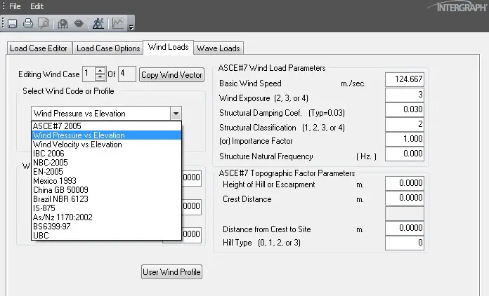
Now run the analysis and go to the load case editor and select Pressure Vs Elevation as shown in Fig. 2
Fig. 2: Load Case Editor showing Wind Pressure Vs Elevation
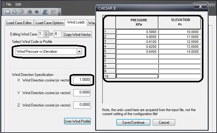
In the next step enter the pressure vs elevation profile in-consistent unit and enter wind direction cosines as shown in Fig. 3. Normally wind analysis is performed considering wind flow from North, South, East, and West direction. Accordingly, Enter +1 or -1 in X or Z direction. Wind analysis is generally not considered in a vertical direction.
Fig. 3: Load Case Editor showing input of pressure vs elevation profile
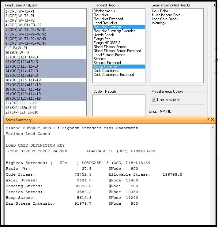
Refer to Fig. 4 and prepare the highlighted load cases additionally for wind analysis. Load cases for L17 to L20 are for code compliance checking and load cases from L5 to L8 are for support and Nozzle load checking.
Fig. 4: Load cases for Wind Analysis
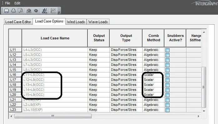
Refer to Fig 5 and make the combination method scalar or absolute for the shown load cases.
Fig. 5: Load case Editor showing load case combination method.
In the final stage run the analysis and check the results. If failing makes suitable adjustments to qualify the same.