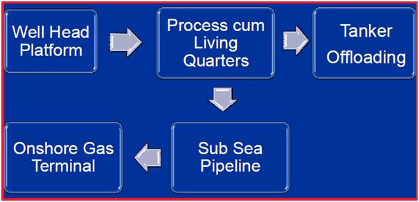
Offshore pipelines are the center stage of the subsea transportation system. Any offshore oil and gas projects constitute a long length of offshore pipelines. These are also known as sub-sea pipelines. In the transportation and delivery of carbon products, offshore pipelines play a major role. But the design and laying of offshore pipelines are not easy. It requires many considerations. In this article, we will explore the basics of offshore pipeline projects in brief.
Why offshore pipelines?
Pipelines are used for transportation and delivery services from historic times due to their own advantages like
Safer
Environment friendly
Least energy requirement
Lowest maintenance costs
Minimal impact on land use pattern
Negligible loss of product in transit
High reliability
What can be transported through Offshore Pipelines?
Offshore pipelines can be used to transport liquids, solids, and gases as per requirement. Normally the following products are used inside offshore pipelines:
All offshore pipeline projects have the following stages before it is ready to take the first fluid.
Conceptual Study
Feasibility Study
Basic Engineering
Detailed Engineering
Construction
Testing & Commissioning
Conceptual Study
In this stage for offshore pipelines, the following major activities are performed.
Establish System Requirement
Evaluate Constraints on System Design
Identify Interface With Other Systems
Develop Design Data Requirements
Assess Construction Methodology
Finalize the Concept
Feasibility Study
The feasibility study is a very important stage for offshore pipeline projects as it evaluates all possible options for the project to decide the feasibility. The major activities of this stage are
Evaluate Technical Options
Eliminate Un-viable Options
Firming up of Process Facilities
Develop Broad System Specifications
Establish Project Cost
Plan Project Implementation Scheme
Finalize Process Scheme & Equipment
Basic Engineering
Basic Engineering is the next important stage for offshore pipeline projects. The major activities involved in this stage are listed below:
Environmental & Process Data Review
Pipeline Routing & Size Optimization
Establish Requirements for
Surveys and Investigations
Material of Construction
Preliminary Analysis
Construction, Testing, and Commissioning
Develop Implementation Schedule
Safety Aspects for offshore pipeline projects
Environmental Parameter and Soil Data
Pipeline Stability
Shore Approaches
Trenching and Burial
Safety of Existing Facilities
Detailed Design & Engineering
The main or the most important stage of any offshore pipeline project phase is detailed engineering. Most of the design works are studied in detail and completed in this stage.
Engineering Design Basis
Route Engineering & Surveys
Engineering analysis and Calculations
Specification and Job Standards
Engineering for Procurement
Drawings for Construction
Installation analysis and Procedures
Design Basis
The engineering design basis provides all the governing criteria to follow in the pipeline project. It provides the
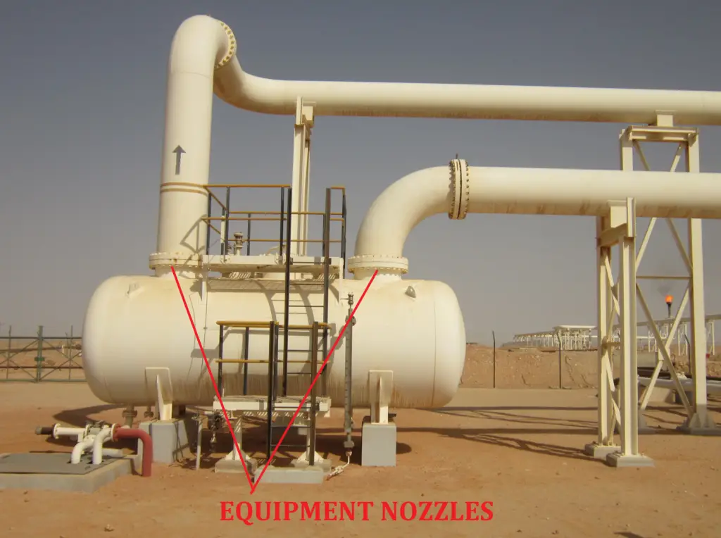
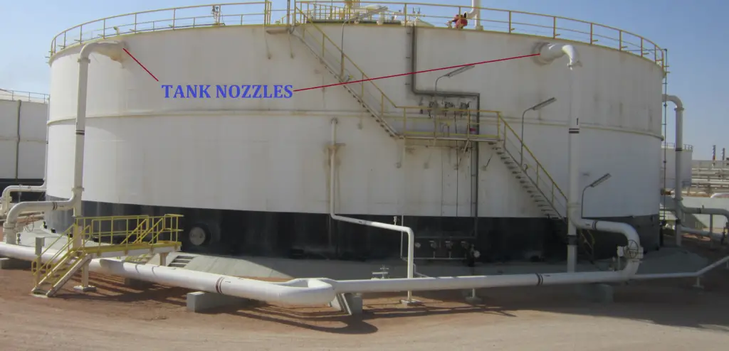
Nozzle loads are the forces and moments that the piping system exerts on the equipment nozzles. One of the important qualification requirements while stress analysis of a piping system is to keep these loads and moments within a given allowable limit which is known as Nozzle load allowable values. Nozzle loads are basically sets of three forces and three moments with respect to three axes. These loads and moments are generated in the nozzle connection due to various factors like Pipe Weight, Design Pressure, Thermal movement, Occasional effects, etc.
One of the major difficulties piping stress engineers face while analyzing any piping system is to keep piping side loads or external loads (forces and moments are combinedly mentioned as loads) on equipment nozzle connection within allowable limits. All equipment to which the piping system is connected is categorized into two groups.
In some organizations, the table value is multiplied with some factors (normally 0.75) while checking nozzle loads for shell and tube heat exchangers.
Normally the mechanical department includes this load table in the equipment purchase requisition and sends it to the equipment vendor while bidding. It is clearly indicated that the nozzle connections must be designed to resist the table values. The equipment vendor reproduces the values in the equipment general arrangement drawing to avoid any confusion at a later stage.
For cases, where the static equipment does not fall into the types mentioned in the above criteria the nozzle loads have to be obtained from the equipment vendor or from some ASME B31.3 code specified standards. A few of such type of equipment and nozzle connection is listed below for your reference:
Loads are to be obtained from the manufacturer, in case the piping side load is more than allowable loads have to be forwarded to the vendor for FEA/vendor acceptance.
Jacketed nozzles connected to Jacketed pressure vessels:
Loads are to be obtained from the manufacturer, in case the piping side load is more than allowable loads have to be forwarded to the vendor for FEA/vendor acceptance.
Pressure vessels made of nonferrous (Aluminium is more common) materials:
Loads are to be obtained from the equipment vendor.
Loads are mentioned in API 661, discuss with the vendor (check internal project specification) if any factor is to be used (Normally a factor of 2 or 3 is used in some organizations).
Nozzles connected to Plate Fin Heat Exchanger:
Refer to API 662 for nozzle loads (There are 2 tables in the standard depending on fluid service (normal service and severe service), check carefully which table to be used)
Tangential nozzles connected to Pressure Vessels:
Loads have to be taken from the manufacturer.
Nozzles whose axis is not perpendicular to the Vessel axis:
Obtain allowable loads from the vendor.
Nozzles connected to API Tanks with diameters more than 36 meters:
Refer to API 650 for nozzle loads (No standard table is provided for load values, you have to determine the loads from equations.)
Refer to API 560 for allowable nozzle loads. Sometimes a factor of 2 or 3 is used for multiplying the table values. Refer to project specifications for the same or discuss it with the vendor.
Normally rotary equipment is designed based on some code-specified standards and accordingly, the limiting loads have to be taken from respective standards. Some such commonly used equipment are mentioned below:
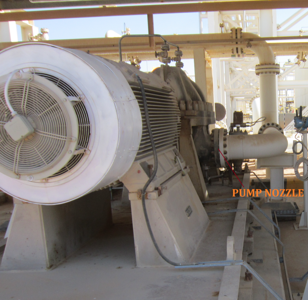
Nozzle Loads for Centrifugal Pumps
For pumps that are designed based on API standards, allowable loads have to be taken from API 610 (If loads are more than allowable values as specified in table 5 of the standard, perform Appendix P). Allowable load values up to nozzle size 16 inch is provided in the table. For higher sizes, the ANSI standard is used. If the pumps are not designed as per API standards (nowadays non API pumps are most frequently used due to its lower costs) obtain loads from the vendor. Sometimes ANSI/HI 9.6.2 is used for nozzle loads in absence of data.
Use API 617 for equipment nozzle loads. Note that combined analysis must be performed for the proper functioning of the compressor. Sometimes the vendor permits more loads so discuss with them.
Steam Turbine:
Refer to NEMA SM23 or API 612 for allowable nozzle loads. Don’t forget to perform combined nozzle load checking. Sometimes the vendor permits more loads so discuss with them.
Positive displacement compressors:
Refer to API 619 or manufacturer allowable loads.
Gas Turbine: Loads are to be obtained from the manufacturer.
Means for Reducing Nozzle Loads
Now if the nozzle load on equipment is found to be more than the allowable values as specified above, first try to get a feel of the reason for the increased load and then try to apply any of the following alternatives to reduce the nozzle loads:
Try to reduce the nozzle load by adding additional flexibility in the piping system (Could be followed if the load is arising because of less flexibility)
If the load is due to the weight of the piping system, provide additional support.
Try to direct the thermal expansion away from the equipment by providing proper restraints (guide or directional anchors).
If the load is more because of friction then try to use PTFE/graphite/Mirror polished SS plates to reduce frictional loads.
Cranes are widely used and extremely powerful construction equipment that makes the life of a construction engineer easier. There is no substitute for cranes for lifting heavy products at great heights. But, the operation of cranes at the construction site is full of hazards and risks. If not handled properly, Cranes have the potential to cause major accidents claiming human lives. Thus crane safety is of utmost importance and must be followed minutely to avoid any major accident during operation. In this article, we will explore the causes of crane accidents and crane safety tips to reduce the chances of accidents involving crane operations.
Major Causes of Crane Accidents
The major causes of crane accidents include:
boom or crane contact with energized power lines (nearly 45% of the cases),
In addition to instability factors, communication, and training, some cranes are not maintained properly nor inspected regularly to ensure safe operation.
Who is at Risk?
Operators
Persons at Crane Site
Crane Terminologies
Crane – Consists of a rotating structure for lifting and lowering horizontally on rubber tires or crawler treads
Boom – An inclined spar, strut, or other long member supporting the hoisting tackle
Boom stops – A device used to limit the angle of the boom at its highest position
Brake – To slow or stop motion by friction or power
Block – Sheaves or grooved pulleys in a frame with hook, eye, and strap
Jib – Extension attached to the boom point to provide added boom length for lifting specified loads.
Boom angle indicator – An accessory device that measures the angle of the boom base section centerline to horizontal
Load – The weight of the object being lifted including:
Load block and hook
Wire rope
Rigging
Boom attachments
Ancillary attachment
Outrigger – Support members attached to the crane’s carrier frame which are used to level the crane
Pendants – Stationary wire ropes used to support the boom
Radius – The horizontal distance from the axis of the rotation of the crane’s superstructure to the center of the suspended load
Superstructure – The rotating frame, gantry, and boom or other operating equipment
Counterweight – Weights used for balancing loads and the weight of the crane in providing stability
Deck – The revolving superstructure or turntable bed.
Drum – The spool or cylindrical member around which cables are wound for raising and lowering loads
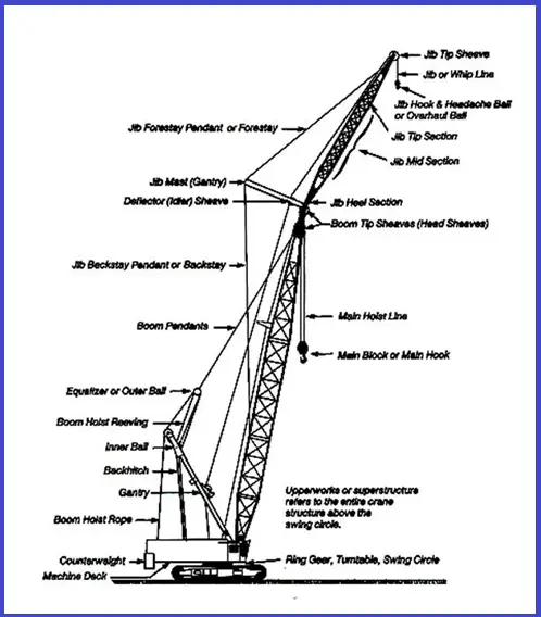
Crane Parts (Fig. 1)
Fig. 1: A typical sketch showing Crane Parts
Types of Cranes
Mobile cranes
Hydraulic cranes
Overhead cranes
Gantry cranes
Tower cranes
Commonly Used Cranes
Hydraulic rough terrain crane
Crawler lattice boom friction crane
Several significant differences between these cranes, primarily in boom hoist and load line controls. The somewhat smooth operation of the boom control adjustments on the hydraulic cranes may falsely suggest that it is simple to operate. The lattice boom friction cranes’ movement in its boom or its adjustment in load position tends to be a little jerky requiring more skill and experience to operate smoothly.
Another difference is the load charts. Due to the fixed boom lengths, the lattice boom friction crane has a more simplified load chart. This requires extensive motion control and anticipation of boom movement to accurately lift or place loads.
The hydraulic crane’s load charts are more extensive making them complicated due to variations in boom length, so more training in multiple charts is required
The differences between these cranes are significant enough to require specific training on each type of crane. Crane operators cannot expect to be totally knowledgeable and proficient in the operation of the many diverse types of cranes available today. They cannot be expected to move from one type of crane to another without adequate education and training on the specifics of each piece of equipment.
Crane Hazards
Improper load rating
Excessive speeds
No hand signals
Inadequate inspection and maintenance
Unguarded parts
Unguarded swing radius
Working too close to power lines
Improper exhaust system
Shattered windows
No steps/guardrails walkways
No boom angle indicator
Not using outriggers
Hazards Associated with Crane Operations
OSHA’s analysis of crane accidents in general industry and construction identified an average of 71 fatalities each year.
A study conducted by OSHA showed that nearly 30% of work-related electrocutions involved cranes.
Although mechanical failures represent only 11% of the causes of crane accidents, they usually result in major accidents involving injuries, fatalities, substantial material costs, and usually spectacular media coverage. Studies and analyses often show they are frequently due to a lack of preventive maintenance or adequate training and/or experience on the part of the personnel involved. Crane operators and other personnel working with cranes need to receive training in crane operations. Cranes and associated rigging equipment must be inspected regularly to identify any existing or potentially unsafe conditions. Regular inspections are before use and during use. If there are problems, get them fixed before continuing work. Preventive maintenance must also be done per the crane manufacturer and/or the supplier’s specifications.
Crane Safety Guidelines
There are various crane safety guidelines that must be followed to reduce the accident potential. Some of these crane safety rules are
1. Proper Planning Before Start-Up
Level the crane and ensure the support surface is firm and able to support the load
Contact power line owners and determine precautions. Know the location and voltage of overhead power lines.
Know the basic crane capacities, limitations, and job site restrictions, such as the location of power lines, unstable soil, or high winds.
Make other personnel aware of hoisting activities.
Barricade areas within a swing radius.
Ensure proper maintenance and inspections.
Determine safe areas to store materials and place machinery.
2. Competent Person
The competent person must inspect all machinery and equipment prior to each use, and during use, to make sure it is in safe operating condition.
If it needs fixing, take it out of service and don’t use it until it is fixed
3. Load Capacity – Speed – Warnings
Make sure the crane operator can see the:
Rated Load Capacities
Operating Speeds
Special Hazard Warning or Instruction
4. Know the Weight of the Load
Refer to the shipping ticket or other documentation
Ensure lift calculations are correct
Ensure the load is within the load chart rating for boom length and load radius of the crane
Crane is rated by the maximum weight it will lift at a minimum radius and minimum boom length – the further from its center point, the less it will lift
Crane Overturning Accidents
Basically, overloading is responsible for a relatively small portion of mobile crane accidents simply because a very small portion of lifted loads is at or near rated loads. In concept, load and load-moment indicators are ideal means to assure cranes will not be overloaded. In practice, they fall short of the ideal. The reasons are many and can only be briefly mentioned here.
Some reasons that load or load-moment indicators are not reliable:
the device has been turned off or is down due to malfunction,
the device is out of calibration, or
operating conditions (wind or operating speeds or out of level) are so far from ideal that the published rating can lead to failure. The mounting of a device is itself no assurance operations will be safe. Just like oil pressure or temperature gauges, those devices are not safety devices; they are indicators that advise a knowledgeable operator of load parameters as an aid in making operating judgments.
Some authorities overstress the value of or need for, load or load-moment indicators. There is no doubt that there are operating situations that require a device of that type, but on the other hand, in certain situations, they offer mixed blessings. It has been demonstrated that there is a tendency for some operators to become overly reliant on the devices and to use them in place of judgment. This can lead to accidents when conditions are not ideal. An untrained or inexperienced operator may use the device as a prop and as a substitute for knowing the machine, the load, and the rating chart.
Operators who do not fully understand the meaning of the values on the rating chart, and who do not understand the limitations of the crane and its ratings, will operate carelessly or will allow untrained, inexperienced supervisors to tell them to pick an unsafe load. The number of operators who do not understand rating charts is surprising. The number of supervisors who know little or nothing about cranes is shocking.
Crane Load Limiting Factors
Not level
Wind
Side loads
On its wheels
Lifting over the side
Use of extensions, jibs, and other attachments
Limits of wire rope, slings, and lifting devices
Mobile Cranes –Lifting Principles
Center of Gravity
Leverage
Stability
Structural Integrity
Four basic lifting principles govern a crane’s mobility and safety during lifting operations:
The Center of Gravity Point in the object where its weight can be assumed to be concentrated or, stated in another way, it is the point in the object around which its weight is evenly distributed. The location of the center of gravity of a mobile crane depends primarily on the weight and location of its heaviest components (boom, carrier, upperworks, and counterweight).
Leverage Cranes use leverage to lift loads. Rotation of the upperworks (cab, boom, counterweight, load) changes the location of the center of gravity, its leverage point or fulcrum.
Stability Relationship of the load weight, angle of the boom, and its radius (distance from the crane’s center of rotation to the center of load) to the center of gravity of the load. Stability could also be affected by the support on which the crane is resting. A crane’s load rating is generally developed for operations under ideal conditions, i.e., a level firm surface. Unlevel surfaces or soft ground, therefore, must be avoided. In areas where soft ground poses a support problem, mats and or blocking should be used to distribute a crane’s load and maintain a level stable condition.
Structural Integrity The crane’s mainframe, crawler track and/or outrigger supports, boom sections, and attachments are all considered part of the structural integrity of lifting. In addition, all wire ropes, including stationary supports or attachment points, help determine lifting capacity and are part of the overall structural integrity of a crane’s lifting capacity.
These elements may also affect structural integrity:
The load chart capacity in relation to stability;
The boom angle limitations affect stability and capacity; and
The knowledge of the length of boom and radius in determining capacity.
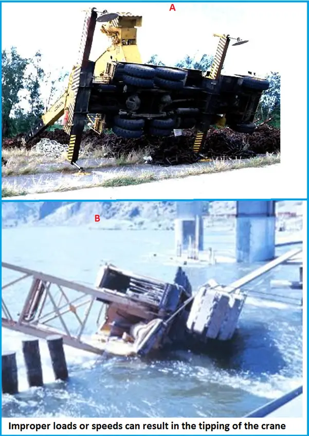
Crane Accident– Overturned Crane
The crane in Fig. 2A overturned when it attempted to lift heavy pieces of metal chain in excess of its load rating. In addition, it was side loading which was not part of the load calculation. Even though the outriggers were out, the weight of the load caused the crane to overturn.
Fig. 2: Example of Overturned Cranes
The crane in Fig. 2B overturned while performing loading operations on a pier. The crane was attempting to remove a metal container from a barge when it tipped and slid into the water. The wind caused the load to swing violently causing the load to go outside the swing radius, at that point the load dropped into the water and took the crane with it.
Precautions
Power Lines: Stay clear from power lines at least 10 feet
Swing Radius: Stay out of the swing radius of the crane–Make sure there are barrier guards showing the swing radius
Operator Visibility: Make sure broken windows or other obstructions do not prevent the operator from seeing
Guardrails: Runways and steps need to have guardrails, handholds, and slip-resistant surfaces
Suspended Loads: Don’t stand under suspended loads
Boom Angle Indicator: A boom angle indicator must be on the crane
Supporting Surface: Cranes must be on a firm supporting surface and level within 1 percent
The grooves must be smooth and free from surface defects that could cause rope damage. The damaged wire rope must be taken out of service.
Rigging Equipment Slings: Types of slings include alloy steel chain, wire rope, metal mesh, natural or synthetic fiber rope, and synthetic web. Immediately remove damaged or defective slings from service.
Annual Inspections: Inspection of the hoisting machinery must be made by a competent person. The employer must maintain a record of these inspections.
What to Inspect
Correct air pressure and no leaks
Tires are properly inflated. Conduct regular inspections of tires for excessive wear or damage
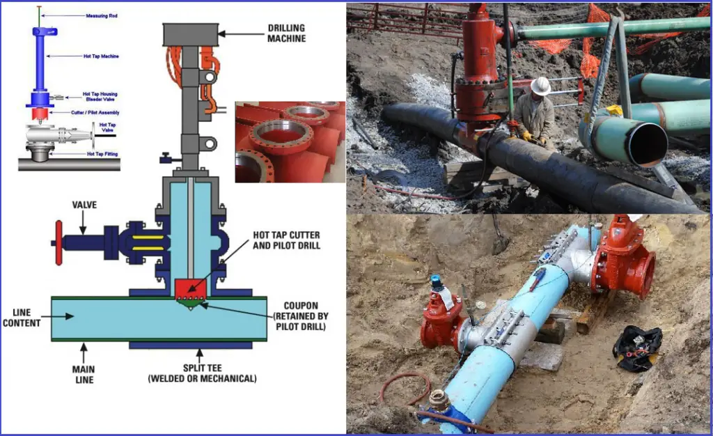
Hot Tap or Pipe Hot Tapping is a proprietary method for adding a branch connection to a “hot” or operating line. The hot Tapping process allows a connection into a pressurized in-service operating system, by drilling or cutting. The hot tap procedure involves attaching a branch connection and valve on the outside of an operating pipeline, and then cutting out the pipeline wall within the branch, and removing the wall section through the valve.
In general, hot taps are done in a piping system. But, it can also be done on pressure vessels and storage tanks to add nozzles. Hot tapping is a highly dangerous operation. Therefore, hot tapping must only be used as the last resort when it is impractical to shut down the system. While preparing a hot tapping specification, care needs to be exercised in inspection, design, and testing. It must be ensured that this operation is done in a safe and reliable manner. Each hot tapping needs to be properly designed, the location of hot tapping thoroughly inspected, and the installation procedures reviewed before starting the operation.
A. What is Hot Tapping?
Hot-tapping is a method of making connections to piping (or other equipment) by attaching a fitting to the system, usually by welding, followed by cutting through the pipe wall at the point of attachment utilizing a hot-tapping machine. This operation is carried out on a live (hot) system without decommissioning or interrupting flow.
Hot tapping is a multi-disciplinary operation that typically involves various departments, each with its own responsibilities. As a result, effective coordination and careful planning among these departments are essential for successful execution.
B. Some Definitions or Terminologies related to Hot-Tapping
Term
Definition
Run pipe
The pipe into which a hot tap is to be made
Branch pipe
The pipe which is to be connected to the run pipe by means of the hot tap.
Coupon
Section of pipe cut out during the hot-tap cutting operation
In-service welding
Welding on a piping system that is flowing or under pressure
Lock plug
Plug which can be set into position inside a hot-tap connection flange in order to retain internal pressure.
Hot Tap Terminologies
Stopple
A proprietary device, to be used in conjunction with a hot tap that blocks a “hot” line is called “Stopple”.
C. Codes and Standards for Hot Tapping
There are various codes and standards that are followed for Hot Tapping in live piping and pipeline systems. Some of them are:
Design Codes: ASME B31.1, B31.3, ISO 13623, ASME B31.4 and B31.8, ASME Sec. VIII Div.1 and 2
Fabrication Codes: ASME BPVC Sec. VIII Div.1
Welding Codes: ASME BPVC Sec. IX
NDT Codes: ASME BPVC Sec. V
Shell DEP 31.38.60.10
API 570
API RP 2201
D. Hot Tapping Procedure | Activity Steps for Pipe Hot Tapping Job
The following activities are involved in performing Hot Tapping Jobs in any project:
Justification
Design
Construction planning
Operations planning
Verification
Execution
Completion
There has to be an agreement that the hot tap for the particular case is technically feasible and justified. During the design data gathering of the existing main pipe, connection design, confirmation of technical feasibility, setting the hydro test pressure, etc. has to be decided. In the next step, welding procedure, welder qualification, safety plan, on-site checks (e.g., inspection of the hot-tap and weld area by visual inspection and NDT), etc. need to be performed. Operations planning involves activities like control of operating conditions, work permits, and emergency procedures. Before execution, all required barriers and mitigations for safe work execution are to be verified to work as planned and that no hydrocarbons are present in the welding area or space. The next step is execution which involves welding, inspection, pressure testing, perforation, etc. The final step is completion which involves activities like reinstatement, updating records, and handover.
Hot Tap being highly hazardous, all activities need to be ensured following a detailed Hot-Tap Procedure Check List.
E. Components of Hot Tapping
Refer to Fig. 1. A typical hot-tapping system consists of
Tapping fittings.
Isolation valve.
Hot tapping machine which includes the cutter, and housing.
Drilling machine or Cutter: The drilling machine usually consists of a mechanically driven telescoping boring bar that controls a cutting tool. A pilot hole into the pipeline wall is bored by the cutting tool in order to center a hole saw that cuts out the “coupon,” or curved section of the pipeline wall.
Fitting: Connection to the existing pipe is made within a fitting, which can be a simply welded nipple for a small (e.g., one inch) connection to a larger pipeline, or a full-encirclement split-sleeve tee for extra support when the branch is the same size as the parent pipeline. The tee wraps completely around the pipeline, and when welded, provides mechanical reinforcement of the branch and carrier pipe.
Valve: The valve on a hot tap connection can be either a block valve or a control valve for the new connection, and must allow the coupon (section of pipeline wall cut out by the drilling machine) to be removed after the cutting operation. Suitable valves include a ball valve or gate valve, but not a plug valve or butterfly valve.
F. Limitations of Hot Tapping
Hot tap connections shall not be made in any of the following cases:
1. Limited by Fluid Types:
Lines carrying the following shall not be hot-tapped.
Any material that may cause metallurgical damage when heated.
2. Limited by Flammability of Fluid:
Hot taps are not suitable for pipes or vessels containing materials that are flammable below atmospheric pressure or mixtures that will support combustion.
Fig. 1: Hot Tapping at the site
3. Limited by Material Degradation:
Hot taps are not suitable if the pipe material to be welded may suffer metallurgical or physical degradation from the heat of welding.
Lines with surface temperatures above 370 degrees C or below -20 degrees C are not suitable for hot tapping.
7. Limitation by Other Process Conditions
Some standards provide additional reservation parameters for hot tapping. Some examples are:
The operating pressure during hot tapping should not be more than 70 bar (g)
The minimum velocity of liquid flow during hot tapping welding should be more than 0.43 m/s to provide cooling during the hot tap welding process. Again, the maximum velocity for liquids should be limited to 1.75 m/s to prevent rapid cooling. Similarly, for purge gas, the minimum velocity to be maintained is 0.4 m/s and the maximum velocity is 9 m/s.
8. Some other limitations are
Equipment Availability: There must be a hot tapping machine available for the temperature pressure and size of the shell.
Tanks: Hot taps on tanks shall be located at least 1 m below the liquid level.
Compressed Air: Compressed air, when there is any possibility of hydrocarbon contamination, shall not be hot tapped, without thorough internal cleaning, or the introduction of inert gas, prior to welding.
Debris Damage: Hot taps shall not be made upstream of any equipment that may be damaged by chips, shavings, and other debris introduced into the line by the hot tapping process. Hot tapping shall not be allowed until systems have been put in place that will positively trap foreign matter.
Minimum Wall: The minimum wall thickness for hot tapping is 5 mm. This wall thickness must be verified by ultrasonic testing on the parent pipe.
Hot tap welding is not to be performed on wet surfaces.
G. Hot Tapping Design
1. Base Material
The material of the run and branch pipe for the hot tapping welding shall be compatible in terms of weldability; the same P-Number can be considered as the basis for compatibility.
2. Dimensions of the Connection:
The dimensions of the connection, the hot tap valve, and the clearances shall be within the limits specified for the hot tapping equipment to be used. This requires data from the most likely contractor or specification of a list of allowable hot-tapping machines for that project. The minimum bore of the valve used shall be large enough to pass the cutter or stopple plug.
3. Size to Size Taps:
A tap equal to the nominal size of the header, such as required for the stoppling of a pipeline, shall be made only when the accurate positioning of the cutter can be guaranteed. This is accomplished by the use of a shop-fabricated split tee. In all other cases, the taps are only allowed at least one pipe size smaller than the pipe to be tapped.
4. Welding on Pipelines under Pressure:
Before welding on lines under pressure, the existing pipe wall shall be determined. A maximum working pressure shall be calculated in accordance with the appropriate ASME B31 code, using the actual wall minus 2.5 mm. The 2.5 mm wall thickness takes into account the molten and heat-affected portion of the base metal which does not contribute to pressure containment.
5. Control of Cuttings:
When using gate valves for hot tapping, orient the valve so that chips from the cutting procedure will not fall into areas where the action of the valve is inhibited. If this is not possible, the hot tap valve shall be provided with a valved drain of not less than 3/4 inch NPS to permit flushing of the valve if needed.
6. Removal of Hot Tap Valve:
When the hot tap valve is to be removed after tapping, as in the case of stoppling, a Lock-O-Ring flange and plug, or approved equal, shall be used unless the equipment can be depressurized and drained prior to removal of the valve.
7. Guide Bars:
When hot taps are made in pipelines that require scraper bars, a Lock-O-Ring, or approved equal, flange and plug and matching insert with bars attached, shall be installed.
8. Loads during Hot Tapping
During the stress analysis of hot tapping of the pipeline or piping system the following loads need to be considered:
Piping Transmitted Loads
Internal Pressure
Hot-Tapping Loads
This will ensure that the hot tap weld will withstand all the loads during the hot tapping operation.
H. Hot Tap Fitting Installation
Positioning the Split Tee and Cutter
The welded branch or split tee shall be accurately positioned so that the axis of the cutter will intersect the axis of the pipe or vessel being tapped at a 90-degree angle unless an angled tap has been specifically approved in the hot tapping procedure. The branch position shall be verified by the assigned inspector prior to making the cut.
Safety Procedures
The hot-tapping contractor shall submit safety procedures with his proposal. The installation, pressure testing, welding, and cutting, shall be in accordance with the approved procedures.
I. Pressure Testing
1. Test Valve:
The hot tap valve shall have a pressure test applied to the seats and body to ensure no leaks prior to use.
2. Test Fluid:
Special attention shall be given to the possibility of boiling or flashing of the test liquid if the surface to be tapped is hot.
3. Hot Tap Test:
When the full assembly is complete, and prior to cutting the coupon, the assembly shall be pressure tested.
4. Test Pressure:
The test pressure for the hot tap connection shall be in accordance with the appropriate ASME B31 code, however, not exceeding any of the following:
(i) The minimum pressure in the pipe or vessel being tapped, while the test is in progress, plus a calculated differential pressure. The differential pressure shall be 1.25 times the allowable external pressure calculated per the ASME SEC VIII D1, paragraph UG-28. The value of L, for this calculation, shall be the total length of the split tee or the inside diameter of the welded nozzle.
(ii) The maximum test pressure of the branch connection flange, or the wall thickness.
(iii) The test pressure of the hot tap connection may be lower than the original hydrostatic test pressure of the pipe or vessel being tapped. This is acceptable since the purpose of the test is to provide some assurance of the integrity of the connection weld. It is not a proof test of the connection. The system being tapped should not be derated because of the lower test pressure of the hot tap connection.
5. Pad Vent Hole
The reinforcing pad of a welded branch shall be provided with a vent hole. The hole shall be plugged in with heavy grease before leaving the job.
Refer to the following video to visualize the hot-tapping operation.
Hot Tap Video by Pro-Pipe
K. FAQ on Hot Tapping
1. What is hot tapping?
Hot tapping is a technique used to create a connection to a pressurized system, such as pipelines or vessels, without shutting down the system. It allows for the installation of new valves, branches, or other equipment while the system remains in operation.
2. When is hot tapping used?
Hot tapping is typically used in situations where:
A system cannot be taken offline due to operational needs.
Quick modifications or repairs are necessary.
The process requires minimal disruption to services.
3. What are the safety precautions for hot tapping?
Safety is paramount in hot-tapping operations. Key precautions include:
Conducting a thorough risk assessment.
Ensuring all personnel are trained and equipped with appropriate PPE (Personal Protective Equipment).
Utilizing certified equipment and following industry standards.
Implementing proper isolation and monitoring procedures.
4. What types of systems can be hot tapped?
Hot tapping can be performed on various types of systems, including:
Gas and oil pipelines
Water distribution systems
Chemical processing facilities
Steam and heating systems
5. What equipment is used in hot tapping?
Common equipment for hot tapping includes:
Hot tap machines
Tapping valves and fittings
Isolation valves
Pressure monitoring instruments
Safety equipment (e.g., fire extinguishers, emergency shutdown systems)
6. How is the hot tapping process carried out?
The hot-tapping process generally involves the following steps:
Preparation: Assess the site and gather necessary equipment.
Isolation: Isolate the area around the intended tap.
Installation: Attach the tapping machine and valve to the existing pipeline or vessel.
Tapping: Cut into the system under controlled conditions, allowing flow to continue.
Completion: Secure the new connection and perform pressure tests to ensure integrity.
7. What are the potential risks of hot tapping?
Potential risks include:
Leaks or spills if not properly managed.
Equipment failure or accidents due to high pressure.
Exposure to hazardous materials.
Fire or explosion in certain environments.
8. How do you ensure a successful hot tap?
To ensure success:
Plan thoroughly and conduct proper training.
Use high-quality equipment and follow industry standards.
Monitor conditions continuously during the operation.
Conduct post-operation inspections to verify the integrity of the new connection.
9. Are there regulations governing hot tapping?
Yes, hot-tapping operations are subject to various industry regulations and standards, which can vary by region and industry. Always consult local regulations and follow best practices outlined by organizations such as the American Society of Mechanical Engineers (ASME) or the American Petroleum Institute (API).
10. Who should perform hot tapping?
Hot tapping should only be performed by trained and experienced personnel familiar with the specific processes and equipment involved. Many companies specialize in hot tapping services, providing skilled technicians to ensure safe and efficient operations.
11. What is a hot tap used for?
A hot tap is used to create a connection to a pressurized pipeline or vessel without shutting down the system. This method allows for the installation of new valves, branches, or other fittings while the system continues to operate, facilitating modifications, repairs, or maintenance without interrupting service.
12. Why do we need hot tapping?
Hot tapping is essential for maintaining continuous operations in critical systems where downtime is costly or impractical. Industries such as oil and gas, water distribution, and chemical processing often rely on hot tapping to enable timely upgrades, repairs, or expansions while minimizing disruption to ongoing processes and ensuring safety.
13. What are the benefits of hot tapping?
The benefits of hot tapping include reduced downtime, increased operational efficiency, and cost savings. By allowing modifications to be made without shutting down the system, hot tapping minimizes interruptions to service, thus preserving production schedules and avoiding the financial impact of system shutdowns. Additionally, it enhances flexibility in managing system upgrades and maintenance.
14. What are the disadvantages of hot tapping?
Despite its advantages, hot tapping poses several disadvantages, including potential safety risks such as leaks, explosions, or equipment failure if not executed properly. The process requires specialized equipment and trained personnel, which can increase project costs. Additionally, there may be limitations based on the type of material or conditions within the existing pipeline that could complicate the hot-tapping operation.
15. What are the differences between hot tapping and cold tapping?
The primary difference between hot tapping and cold tapping lies in the operational status of the system being tapped. Hot tapping involves making a connection while the system is pressurized and in operation, allowing for immediate flow without interruption. In contrast, cold tapping is performed on a system that has been depressurized and shut down, requiring more extensive planning and potentially longer downtime. Consequently, hot tapping is generally more complex but offers the advantage of maintaining continuous service.
L. Detailed Course on “Hot Tapping in Pipeline and Piping Industry”
The Corrosion Under Insulation (CUI) war has been fought for many years in the chemical and petrochemical industry. Corrosion Under Insulation is severe localized corrosion damage that is caused by the moisture (intruding water) present on the external surface of insulated equipment. The corrosion processes are well understood, yet corrosion under insulation or CUI often goes undetected until the damage is significant, which may lead to catastrophic failures, e.g., on equipment operating under high pressure. The industries that are highly impacted by CUI are
CUI (Corrosion under insulation) cost studies have shown that:
40 to 60 % of pipe maintenance costs are caused by CUI
NDE/inspection costs with a high confidence level for detecting CUI are equal to or exceed field painting costs
Approximately 10 % of the total maintenance budget is spent repairing damage from Corrosion under insulation or CUl
If corrosion under insulation is not detected in the proper time, it can lead to failures like explosions, leaks, downtime, equipment failure, etc. The major risks and effects of CUI can be summarized as follows:
Structural Integrity Loss: Weakening of pipes, vessels, equipment
Increased Maintenance: Costly and frequent repairs for hidden damage
Safety Hazards: Potential leaks, ruptures, or fire risks
Production Downtime: Repairs lead to shutdowns and delays
Environmental Impact: Risk of hazardous spills affecting surroundings
Corrosion Under Insulation Temperature Range
General temperature ranges in which the risk of Corrosion Under Insulation is prevalent are
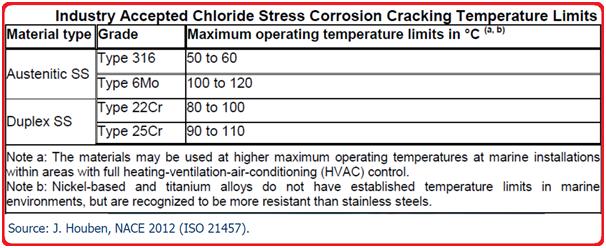
Carbon steel: -4 °C to + 175 °C: Risk of CUI (highest risk area: +60 °C to +120 °C)
Stainless steel: +50 °C to +175 °C
Insulation of process equipment is normally implemented when the outer steel temperature exceeds 50 °C (due to the risk of work-related injuries as well as heat loss).
Mechanism of Corrosion Under Insulation
CUI involves the requirement of the following three elements:
Availability of oxygen.
High temperature.
The concentration of dissolved species.
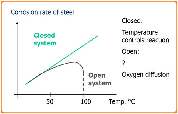
In general, as temperature increases, the corrosion rate reduces as the amount of dissolved oxygen decreases. But when the surface is covered by insulation, moisture makes it a closed system and retains the dissolved oxygen. In some cases, chlorides and acids may be present in the insulation, which greatly promotes corrosion of the underlying surface in the presence of moisture.
For oxygen corrosion to happen, there needs to be some water or moisture on the steel surface. Water usually gets in through cracks or damage in the insulation jacket, which can happen because of poor installation, wear and tear over time, or damage during use. The water typically comes from rain, deluge systems, spills from operations, leaking steam lines, or condensation from humid environments. Depending on the insulation’s ability to absorb water and the temperature of the component, water might stick around. Sometimes, if the conditions are right, the insulation might stay wet and never fully dry out. CUI (Corrosion Under Insulation) can usually be broken down into four types:
Low temperature (like cryogenic or super-cold conditions)
Sweating service (when the temperature is below the dew point)
High temperature
Cyclic temperature (when temperatures go up and down)
For CUI to happen, there need to be four things: an anode, a cathode, an electrolyte, and a way for electricity to flow between them.
In simple terms, the electrolyte in CUI is oxygenated water, which might have contaminants that can speed up the corrosion process.
Let’s look at how this works in practice on a pipe or pressure vessel with thermal insulation. Once water gets past the insulation, it either gets absorbed or trapped. When the water touches the hot steel, it evaporates. This vapor then moves through the insulation to the cooler outer jacket or barrier, where it condenses. The water that condenses then moves back toward the hot steel, and the cycle repeats. Because of this cycle of evaporation and condensation, contaminants can build up on the steel surface. These contaminants can damage the steel’s coating and eventually lead to CUI. This cycle can also damage the insulation, making it less effective. Insulation that holds less water and dries out faster is usually better at resisting CUI damage. Also, keeping the insulation jacket intact and the steel’s external coating in good condition are key factors in reducing CUI risk. Fig. 1 below shows a typical schematic of the CUI process.
Fig. 1: Schematic of Corrosion Under Insulation Mechanism
Factors Affecting Corrosion Under Insulation
The major factors that affect the corrosion process under insulation (CUI) damage are:
Frequency and duration of the moisture exposure
Service temperature.
Types of insulation and protective barrier conditions.
Cyclic operation modes.
Corrosivity of the environment
Type of climate where the system is installed.
Proximity to humidity-causing equipment like cooling towers, etc
Damage Methodology in Corrosion Under Insulation (CUI)
CUI on carbon and low-alloy steels typically results in localized corrosion or pitting, though in severe cases, the damage can be widespread. This form of corrosion happens when moisture and oxygen are present, causing damage when water gets trapped under the insulation and comes in contact with the exposed steel. For these steels, CUI usually occurs at operating temperatures between 10°F (–12°C) and 350°F (175°C).
When insulation is removed, the damage often shows up as a loose, flaky scale on the corroded component. In some cases, the corrosion looks like carbuncle-type pitting, often found under a failed paint or coating. Localized CUI can cause pin-hole leaks, and in extreme cases, it can weaken the structure or pressure capacity of the equipment, potentially leading to a plastic collapse. As the temperature of the metal increases, corrosion rates tend to rise—up to the point where the water evaporates quickly. For insulated components, corrosion is typically worse when metal temperatures are between 212°F (100°C) and 350°F (175°C), because water doesn’t vaporize as easily, and the insulation remains wet.
The severity and rate of corrosion in pressure equipment due to CUI depend on several factors:
The wet exposure cycle (how long and how often the component is exposed to moisture)
The corrosiveness of the water or environment
Failure of protective barriers, like paint or insulation jackets
There are several controllable factors that influence the likelihood of in-service CUI, including the design of the equipment, the choice of insulation and external coatings, operating conditions, construction methods, and maintenance or inspection practices.
For austenitic and duplex stainless steel components, CUI can lead to Erosion Corrosion Stress Corrosion Cracking (ECSCC). The damage usually appears as surface cracks that spread out in multiple directions, often visible as a craze-cracked pattern on the surface. These cracks can worsen over time and lead to leaks, ductile tearing, or even fractures. Interestingly, the material may not show obvious signs of corrosion. ECSCC occurs when tensile stress (often from weld residual stress), temperature, and an aqueous chloride environment combine. Dissolved oxygen also increases the risk of cracking. The most critical temperature range for ECSCC is between 140°F (60°C) and 400°F (205°C).
Austenitic stainless steels (like 300-series) are particularly vulnerable to ECSCC, while duplex stainless steels are generally more resistant. Nickel-based alloys tend to offer high resistance, although they’re not completely immune. The amount of nickel in the alloy plays a big role in its overall resistance to ECSCC. Alloys with 8% to 12% nickel are the most susceptible, while those with nickel content above 35% are highly resistant, and alloys with more than 45% nickel are almost immune to ECSCC. On the other hand, carbon steels, low-alloy steels, and 400-series stainless steels are not susceptible to ECSCC.
Corrosion under Insulation of Carbon Steel
Insulated carbon steel corrodes due to:
Infiltration of water under insulation (rain, process liquids, firewater, etc.)
Condensation water
Ingress of external contaminants
The insulation material may also contribute to CUI:
Creates a crevice for water retention
May absorb water
May leach contaminants that increase the corrosion rate
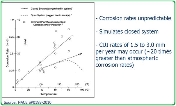
Temperature and oxygen – corrosion rate for CUI
Fig. 2: Curve Showing the Corrosion rate of Steel with respect to temperature.
Chlorides (or other halides) in the presence of water are transported to the hot surface
The chlorides are concentrated by evaporation of the water
The chloride concentration reaches a critical level, causing stress corrosion cracking (SCC). (The critical chloride concentration depends on Temperature and alloy type.)
The insulation material may also contribute to CUI in the following ways:
Creates a crevice for water retention
May absorb water
May leach contaminants (e.g. chlorides) that cause ESCC
Fig. 4: Industry-Accepted Chloride Stress Corrosion Cracking Temperature Limits
How is CUI avoided?
By preventing moisture from entering the insulation material and the steel surface, corrosion under insulation can be prevented. These can be achieved by
Correct selection and design of the insulation material
Good design of the item to be insulated—e.g. it is difficult to insulate around flanges, taps, flowmeters, supports, etc.
The cover above the insulated item (against rainfall, etc.).
Application of corrosion protection
On average, 60% of all insulation in service for more than 10 years will contain corrosion-inducing moisture, which will result in corrosion under insulation.
Carbon steel:
The following steps are followed to prevent corrosion under insulation for carbon steel piping/equipment materials.
Organic coatings
Thermal-sprayed aluminum (TSA)
Personnel protecting cages
Stainless steel (austenitic or duplex)
To prevent the CUI of stainless steel materials, the below-mentioned steps are taken:
Organic coatings
Thermal-sprayed aluminum (TSA)
Al-foil wrapping (prevents ESCC and pitting)
Personnel protecting cages.
Organic coatings on carbon steel
Experience shows that organic protective coatings on piping in CUI service range from 5-13 years
Once the protective life is reached, field re-painting is necessary (or periodic NDE in order to monitor CUI).
Coatings may be damaged during handling and installation – leaving unprotected areas.
Important parameters for coatings used for CUI prevention: – High permeability resistance (barrier protection) – High flexibility (for cyclic temperature service)
Methods of CUI protection
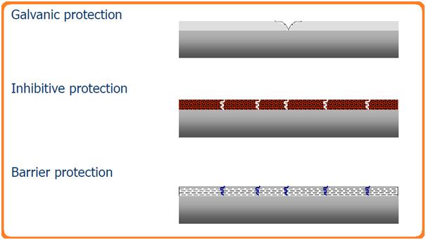
The following image (Fig. 4) shows the methods to prevent various types of corrosion under insulation.
Fig. 5: Methods of protection
The common ways to prevent CUI are:
Closed-Cell Insulation: Limits water absorption, reduces risk
Metal Cladding: Proper sealing and installation block moisture
Drainage Design: Ensures trapped moisture can escape
Material Choice: Ensures long-term asset protection
Sealing Techniques: Properly sealed systems minimize moisture entry
Protective Coatings: Anti-corrosion coatings on metal surfaces
Vapor Barriers: Prevents moisture infiltration
Temperature Control: Reduces condensation and moisture retention
Preventive Inspections: Scheduled checks to identify potential CUI
Controlled Environments: Where possible, limiting exposure helps prevent CUI
Thermal Sprayed Aluminium (TSA) to prevent corrosion under insulation
TSA may provide long-term corrosion protection at significant life cycle cost savings, however at higher initial costs.
TSA provides atmospheric corrosion protection for more than 40 years.
Has been recorded to provide 25-30 years of maintenance and inspection-free CUI service.
Application by electric arc or flame spray.
It requires high-quality surface preparation and strict application control.
Advantages of TSA in CUI prevention:
The coating is robust
Minor pores/damages are protected by the surrounding coating
No under-rusting
Unlimited construction sizes
No risk of deformations (”cold process”)
Disadvantages of TSA:
No treatment in hollow spaces, inside pipes, etc.
The treatment prescribes a certain structural design
Sharp edges must be chamfered/rounded
Often large variations in layer thickness
Quality control
Price
Corrosion Under Insulation Prevention Strategy
Data from operating facilities shows that water-free insulation is not practical in aging facilities. Thus a CUI prevention strategy is necessary in order to provide long-term and reliable prevention of CUI:
A choice between strategies:
Organic coatings on carbon steel; Ongoing re-painting; NDE (does not prevent CUI but predicts remaining life).
TSA on Carbon Steel
Stainless steel (+ TSA or Al foil wrapping) Initial, maintenance, and inspection costs need to be assessed for each choice in order to give the lowest total lifetime cost.
Corrosion Under Insulation Inspection
Various codes and standards provide guidelines for corrosion under insulation inspection methods as listed below:
API 510 covers the CUI inspection in clause 5.5.6 of the standard that says inspection for CUI must be considered for externally insulated vessels and those that are in intermittent service.
API 570, Piping Inspection Code provides guidance to determine the piping systems susceptible to CUI in clause 5.2.1 and clause 5.4.2.
API RP 574, in clause 6.3.3 gives a reference to corrosion under insulation.
API RP 583 provides a detailed overview of CUI.
ASTM STP 880, provides information on corrosion problems on thermally insulated plant equipment and piping components.
NACE SP0198 provides detailed guidance on the Control of Corrosion Under Thermal Insulation and Fireproofing Materials.
Corrosion under insulation is detected by any of the following inspection methods:
Systems operating intermittently above 120 degrees C
Fireproofed support skirts (CUF).
Anchor bolts covered by fireproofing (CUF).
The bottom section of horizontal vessels (like the lower third or half).
Irregularly shaped parts that make insulation difficult to install (like davit arms, lifting lugs, or body flanges).
Carbon or low-alloy steel flanges, bolts, and parts under insulation in high-alloy piping systems.
Places where insulation plugs are missing or removed for piping thickness measurements.
Valves and fittings with tricky, irregular insulation surfaces.
Spots where insulation jacketing meets equipment at places like manways, nozzles, lifting lugs, platform clips, brackets, supports, gussets, stiffening rings, and other fittings (this includes equipment in cold or cryogenic service, too).
Insulation seams on the top of horizontal piping runs, or areas where the insulation jacketing isn’t properly sealed or overlapped.
Areas downwind of cooling towers or places exposed to cooling tower mist.
Places where caulking is missing, hardened, or peeling off the insulation jacketing.
Areas where the insulation jacketing is bulging or stained (this could point to corrosion buildup).
Locations where the banding on insulation jacketing is missing or damaged.
Areas where mechanical or flow-induced vibrations have damaged the insulation jacketing.
Equipment exposed to steam vents.
Areas exposed to process spills, moisture, or acid vapors.
Any region at risk of being exposed to deluge systems.
Areas insulated just for personnel protection.
Areas where the coatings or wraps under the insulation are visibly deteriorated.
Any areas with leaking steam tracing.
Pipe and flanges on pressure safety valves.
Systems that heat up and cool down intermittently above 250°F (120°C).
Systems operating below the atmospheric dew point.
Systems that cycle through the dew point of the atmosphere.
Ice-to-air interfaces on insulated systems that freeze and thaw repeatedly.
Insulation termination points on vessels or pipes, like flanged joints.
Equipment with insulation support rings welded directly to the vessel wall (no stand-off), especially around ladder clips, platform clips, nozzles, and stiffening rings.
Pipes or equipment with leaking steam tracing or near steam tracing penetrations.
Localized damage to paint or external coating systems.
Places where water naturally collects and can’t drain or evaporate properly (like insulation support rings on vertical equipment or poorly terminated fireproofing).
Piping system deadlegs (like vents, drains, etc.).
Pipe hangers and other support points.
Where insulation ends on vertical piping.
The first few feet of horizontal pipe runs near the bottom of vertical runs.
Bolted-on pipe shoes.
Low points in piping where the insulation system is breached, like in unsupported piping spans.
Insulation support rings under damaged or poorly caulked insulation on vertical equipment heads.
Insulated zones at support skirt-to-shell transition regions.