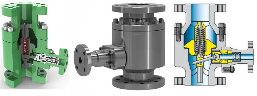
An automatic recirculation valve or ARV is a multifunctional valve. ARV ensures that a pre-determined minimum flow is transferred through a centrifugal pump at all times. So an automatic recirculation valve (Fig. 1) is basically a pump protection device. To avoid permanent damage (destruction) from cavitation and overheating (thermal damage) these valves serve a very important function.
Fig. 1: Automatic Recirculation Valve
Working Principle of Automatic Recirculation Valve
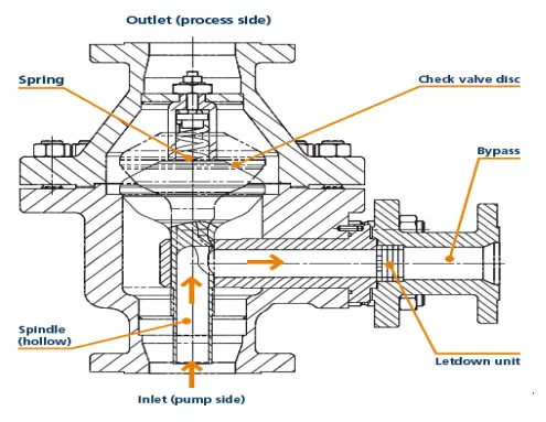
The heart of the automatic recirculation valve (ARV) is a check valve disk that senses the flow rate of the fluid. The valve disk is flow-sensitive and not pressure-sensitive. It controls the fluid flow and ensures that a specified fluid volume passes through. The controlling characteristics result in a consistent and stable flow over a wide range of pressure.
At the full capacity of the valve disk, the bypass closes. Again, when the flow decreases, the action is reversed and there is an increase in the flow rate. The fluid in that situation gets into the bypass system which is controlled by the orifices and is found at the bottom of the disk.
The fluid then flows through the annulus directing it to the outlet. The disk is lifted with an increase in the fluid flow. As a result, the bypass element which is important for the functioning of the bypass closes to limit the recirculation. This guarantees that the recirculation flow is more than the lowest volume of the flowing fluid through the pump.
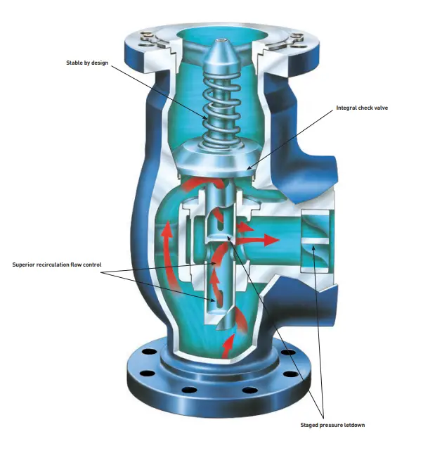
Fig. 2: Typical Automatic Recirculation Valve
So the automatic recirculation valve sets out four functions in one body. They are:
Flow perception: The valve disc of the ARV automatically perceives the main flow of the processing system. Then according to the flow, it determines the main valve and bypass valve disc position.
Recirculation control: Automatic recirculation valve automatically adjust pump H – Q characteristics to realize recycling.
Bypass multistage pressure reducing: The bypass control system of the Automatic recirculation valve reduces the backflow medium from the high-pressure pump outlet to appropriate backflow to the low-pressure storage device with low noise and small wear.
Check: The automatic recirculation valve also provides a check valve effect that prevents the liquid backflow to the pump body.
Applications of Automatic Recirculation Valve
A common application is to protect pumps that handle hot water for boiler feeding or cooling water plants, where partial evaporation of the water content might otherwise cause the pump to run dry. Even in situations, when the flow rate of the main valve to the boiler is completely shut off, a minimum flow is maintained.
Another application of an automatic recirculation valve is to protect high-performance pumps during a start-up phase. In this scenario, several pumps are used in parallel with one on standby. The pump’s automatic recirculation valve enables the change to occur without damaging the pumps. In the Power, Paper & Pulp, Maritime, Refining, Fire protection systems, and Chemical industries, an automatic recirculation valve is widely used.
The bypass fully opens when the disk closes and there is no fluid flow. It helps to protect the pump from damage that would result if the pump continued to operate with no fluid.
Advantages of Automatic Recirculation Valve
The main advantages of an Automatic Recirculation Valve are:
Combines both check and bypass features
No external actuation required
low maintenance and reliable
Proprietary Cv calculation system
Cavitation prevention
Unique and stable design
Minimum flow protection
Easy installation
3 Phase Slurry and High-pressure variants available
Eliminate external power source
Eliminates installation and maintenance of complex conventional flow control loops
Centrifugal Pump Protection Scenarios using Automatic Recirculation Valve (ARV)
Fig. 3: Centrifugal Pump Protection
In a Centrifugal pump, the mechanical energy is transformed into pressure energy by means of centrifugal force. The impeller rotation acting on the fluid within the pump generates the centrifugal force. To avoid overheating, The pump always needs a minimum liquid flow. If the predefined minimum flow is not maintained, permanent pump damage can occur. Four different pump protection scenarios are reviewed below.
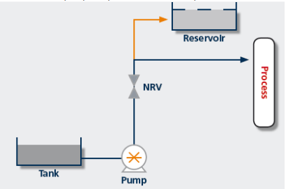
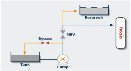
1) Non-return scenario
The pump does not have backflow prevention and therefore, the product will flow back through it once stopped. Therefore, A non-return valve (NRV) is always placed after the pump outlet. A reservoir is used to take the pump output when there is no process demand.
Fig. 4: Non-Return Scenario of Centrifugal Pump
2) Continuous flow scenario
To allow the required minimum flow back to the pump inlet, A manual bypass or leakage path can be added. This is a simple and effective system, which is in constant operation and therefore is inefficient and costly (energy costs).
Fig. 5: Continuous Flow Scenario of Centrifugal Pump
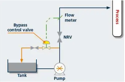
3) Control valve scenario
This comprehensive control valve solution is highly effective. In this scenario, a flow control valve is connected to a flow meter and allows the mainline flow to be metered. The control valve opens when the mainline flow decreases which allows the correct minimum flow required. However, this is a highly capital-intensive solution. It requires flow metering equipment, control, and non-return valves. No reservoir is required.
Fig. 6: Control Valve scenario of Centrifugal Pump
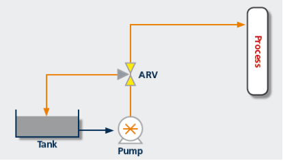
4) Automatic Recirculation Valve solution
The previous approach is costly and stands and falls within the integrity of the control system. An alternative and safer system are to combine the non-return valve, the bypass valve, and the control valve into an interconnected unit, known as “the automatic recirculation valve”. This valve closes during the no-flow condition automatically opening the bypass line, which is sized for minimum flow. When the mainline takes flow but less than the minimum, the bypass line, and the mainline are both partially open.
Fig. 7: Automatic Recirculation Valve Scenario
About the Author: Part of this article is prepared by Ms. Namita Modak, a Chemical Engineer with 14+ years of experience. Click here to know more about her.
Plug Valves: Parts, Working, Types, Symbol, Applications, Advantages, and Disadvantages
A plug valve is a quarter-turn rotary motion manual valve. It uses a cylindrical or tapered plug (plug-shaped disk) to permit or prevent straight-through flow through the body. Plug valves offer a straightway passage through the ports so that fluid can flow through the opening plug with a minimum of turbulence. Flow can be in either direction fully open or fully closed.
The plug valves have been used in many different fluid services. Their performance is good in slurry applications. They are used in bubble-tight services as an on-off stop valve. They are used in air, gaseous & vapor services, Natural gas & oil piping systems, food-processing, nonabrasive slurry, vacuum, pharmaceutical services, and vacuum to high-pressure applications. They are good for on-off valves, diverting services, and moderate throttling. Initially, Plug valves were designed to replace gate valves as plug valves with their quarter-turn action can easily open and close against the flow as compared to a gate valve.
Plug valves are usually preferred for low-pressure–low-temperature services. Plug valves having body lining with materials like polytetrafluoroethylene (PTFE) can be used for corrosive chemical services.
To handle abrasive and sticky fluids, special designs are required. Plug valves are usually found in sizes up to 18 in (DN 450) and in the lower-pressure classes [ANSI Classes 150 and 300 (PN 16 and 40)]. In this article, we will explore the parts, working principles, types, symbols, advantages, and disadvantages of Plug Valves.
Components of a Plug Valve
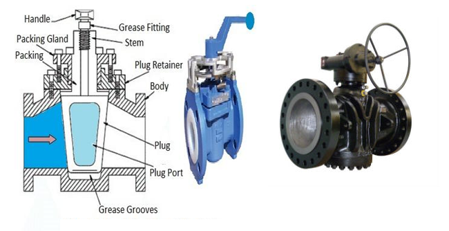
Plug valves have all the general parts such as stem, body, disc, and bonnet. It is different from other valves due to its plug disc design.
The Plug Valve Body:
The valve body has all the internal components of the valve. The body connects to the pipes through an end connection.
The Plug valve Stem:
The stem of the valve connects the disc (or disk) to the actuator. This helps in transferring the movement of the actuator to the plug disc thereby opening or closing the plug disc. The plug valve has a little stem that connects to the disc.
Fig. 1: Parts of a Plug Valve
The Plug valve disc
The plug disc which is known as the tapered disc acts as a plug hence differentiating the plug valve and the globe valve. Out of all the valves, the plug valve, ball valve, and globe valve have some similarities. The major difference is in the way that how the disc looks like. The Globe valve has a cylindrical disc. The plug valve has a solid metal piece with tapered ends.
Plug Valve Ports
An important feature of a plug valve is its easy adaptation to multiport construction. In general, Multiport plug valves are used widely. They provide various benefits like:
Simplified piping and installation
More convenient operation than multiple gate valves.
Depending upon the number of ports in the plug valve, a multiport plug valve can eliminate four conventional shut-off valves.
Plug valves have the following port patterns:
Round opening: It has round ports in both the plug and body.
Rectangular opening: It has rectangular ports of the full bore section.
Standard opening: In this, the area through the valve is less than the area of the standard pipe.
Diamond opening: It has a diamond-shaped opening through the valve.
Multi-port: with three or more pipe connections used for transferring services.
Venturi design: It has reduced area opening with Venturi flow through the body.
Plug Valve Working Principle
The plug valve comprises a body with tapered or parallel seating into which a plug fits. The plug is formed with a port, and the position of the port controls the amount of opening through the valve. Ports are known as the openings in the valve body through which fluid can enter or leave. A 90-degree of plug fully opens or closes the fluid flow. The plug valve is not as efficient as ball valves and can only operate fully open or closed.
When the opening in the plug is in line with the inlet and outlet ports, flow continues through the valve. A pressure drop occurs through the reduced area of the plug port. However, with a full-area cylindrical plug, the pressure drop is minimal.
When the hand operator is turned to the full quarter-turn position (90°), the plug’s opening is turned perpendicular to the flow stream, with the edges of the plug rotating through the sealing device (sleeve, lubricant, etc.). When the full quarter-turn rotation is reached, the port is completely perpendicular to the flow stream, creating a complete shutoff.
In throttling situations, where the plug is placed in a mid-turn position, the plug takes a double pressure drop. The inlet port’s flow area is reduced by turning of the plug away from the full-port position, taking a pressure drop at that point. The flow then moves into the full-port area inside the plug, where a pressure recovery takes place, followed by another restriction at the outlet port. Leakage is prevented through the seat by the compression of the plug against the sleeve or other sealing mechanism, while the packing or the collar–diaphragm assembly prevents leakage through the stem.
With three-way valve arrangements requiring diverting flow, the flow enters the inlet and moves through the plug, which channels the flow to one of the other two outlets. When the plug is moved 90°, the flow is channeled to the other outlet. At a midway position, the flow may be equally diverted to both outlets. With combining flow, flow is directed from two inlets to a single outlet. In order for some of these arrangements to occur, the plug must be turned by half-turn (180°) instead of the typical quarter-turn action.
With larger plug-valve sizes [3 in (DN 80) or larger], the torque required for seal breakout may become somewhat excessive. This is caused by the larger contact surface between the plug and sealing device as well as any adverse operating conditions, such as a high process pressure, temperature extreme, corrosion deposits, etc. In this case, hand levers are typically replaced with geared handwheels, which reduce the torque requirement significantly.
The simple plug valve is suitable for low-pressure, low-temperature applications and is made in large sizes of 250 to 300 mm. The main limitation of the plug valve is that if wide variations in fluid temperature are involved then differential expansion is inevitable, leading either to undue stiffness of operation or loss of pressure-tightness.
The plug may be tapered, or parallel and the movement may be plain or lubricated. Another variation is known as the ball plug valve, in which the plug is spherical, having circular ports rotating between circular seats of the concave section.
Types of Plug Valves / Plug Valve Types
In general, there are four types of plug valves. They are:
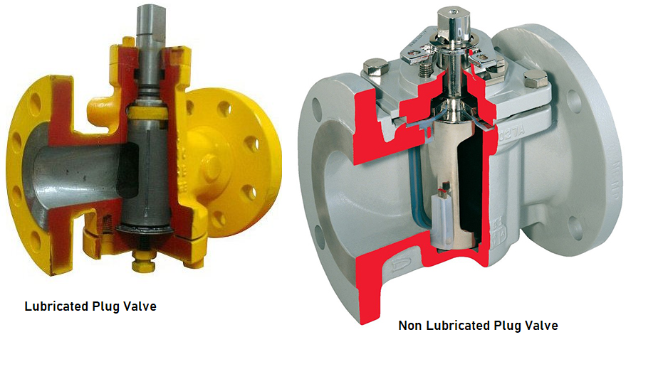
Lubricated Plug Valves
Non-lubricated Plug Valves
Eccentric Plug Valve, and
Expanding Plug Valve
Lubricated Plug valves:
These valves use lubricants or sealants to ease their operation over a wide range of operating pressure. The lubrication film which is used between the plug and body provides a seal that requires periodic lubricant injection. The sealant must be like that it does not get washed away with the fluid as the fluid can get contaminated and it should be able to withstand line temperature. These lubricants in plug valves are mostly plastic sealants. The use of an effective sealant with properties such as proper elasticity, resistance to chemicals, and its ability to form an impervious seal around each body part is essential. The lubricating film also protects the metal surfaces between the plug and the body from corrosion.
Lubricated plug valves are manufactured in sizes ranging from DN 15 to DN 900. They are used in applications with pressures over 2500 psi.
Fig. 2: Lubricated vs Non-lubricated Plug Valves
Non-Lubricated plug valves:
These plug valves are usually used for lower-pressure lines. These valves contain an elastomeric body liner or sleeve installed in the body cavity. The plug that is tapered and polished acts like a wedge and tends to press the sleeve against the body. Thus the sleeve reduces the friction between the plug and the body.
There are three types of non-lubricated plug valves:
Lift-type plug valve
Elastomer-sleeved plug valve
Fully lined plug valve
Lift type plug valve provides a mechanical lifting arrangement to disengage the tapered plug from the seating surface to permit easy rotation. The lifting can be achieved by an external lever.
The elastomer-sleeved plug valve has an elastomer sleeve. It is a TFFE sleeve that surrounds the plug completely. The elastomer sleeve is engaged and locked in place through a metal body. This sleeve has less coefficient of friction and is also self-lubricated.
Fully lined plug valve: These types of valves use inexpensive ductile iron or cast iron body. The body and plug of the valve are fully lined with Teflon in a way giving the valve the ability to resist corrosive fluids using iron as the body material.
Eccentric Plug Valve
This type of plug valve design uses a half plug. This design helps in applications requiring a higher seating force with minimal friction from the open to the closed position. Improved shut-off capabilities are the main feature of the torque seated valves. Eccentric plug valves find application in a wide range of flow control and isolation services. Some of the typical applications of eccentric plug valves are clean and dirty water, sewage, sludge and slurries, air, and other services.
Expanding Plug Valve
Expanding plug valves are complex in design. They use multiple components allowing the plug valve to expand mechanically and give it a true double block and bleed function in one valve. This type of plug valve uses a mechanism that rotates between the open and closed positions and protects both seals from the flow path. The body and seals do not contact each other during rotation which avoids wear or abrasion to the seals. For applications not requiring double isolation, expanding plug valves are often used to prevent product contamination.
Plug Valve types by Pattern
Based on patterns, plug valves are categorized as follows:
Round opening- Full-bore round ports in both plug and body.
Rectangular opening with rectangular-shaped ports of full-bore section.
The standard opening where the area through the valve is less than the area of the standard pipe.
Diamond port where the opening through the valve is diamond-shaped.
Multiport with three or more pipe connections.
Venturi design with reduced area porting and featuring venturi flow through the body.
Short plug valves with reduced area ports and reduced face-to-face dimensions.
Vertical plug valves with reduced area seating ports and the plug passages reduced in section to form a throat.
Plug Valve Materials
Plug valves can be produced from a variety of materials; both metallic and plastic. The most common plug valve materials are
Steel
Stainless Steel
Bronze
Brass
Plastic, etc
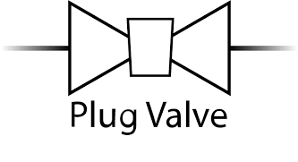
Plug Valve Symbol
In P&ID the following plug valve symbol is used for identification and differentiating from other valves.
Fig. 3: Plug Valve Symbol
Pressure Balanced Taper Plug Valves
In larger taper-plug valves, pressure-balanced plugs are fitted for very high static pressure applications. With a non-pressure balanced plug, line pressure in an open valve can find its way into the larger end chamber that exists below the plug. This creates a resultant force that tends to push the plug into its tapered seat causing a danger of taper locking.
With a pressure-balanced plug valve, the live line pressure replaces the sealant pressure by allowing the line to pressurize the small end chamber. A balancing force is generated which prevents the taper lock.
The pressure-balanced system consists of two holes in the plug connecting chambers at each end of the plug with the line pressure. The hole in the small end of the plug contains a non-return valve. This enables sealant pressure to be built up if necessary while allowing access to the line pressure to the small end chamber. Thus the pressure in the large end chamber always equals the line pressure and the pressure in the small end chamber is always equal to or greater than the line pressure which prevents the taper locking.
Advantages of plug valve
The main advantages of a plug valve are:
It has a simple design and fewer parts
It can be quickly opened or close.
This valve offers minimal resistance to flow.
The use of multi-port designs helps in reducing the number of valves needed and permits a change in the flow direction.
It provides a reliable leak-tight service.
They are easy to clean and can be done without removing the body from the piping system.
Disadvantages of plug valve
The limitations or drawbacks of a plug valve are:
As a large amount of friction is required to rotate the plug, which results in greater force to operate these valves.
Actuators are required for larger valves.
These plug valves cost more than ball valves which have a similar design.
Pressure drop is more due to reducing port.
Codes and Standards for Plug Valve Design
The industry codes and standards governing the plug valve design, test, and inspection are:
ASME B16.10-Face-to-Face and End-to-End Valve Dimensions
API 599 – Metal Plug Valves – Flanged, Threaded, and Welding Ends
MSS SP 25 – Standard marking system for valves, fittings, flanges & unions
MSS SP 78- Gray Iron Plug Valves, Flanged and Threaded Ends
Applications of Plug Valves
As stated earlier, Plug valves are suitable for a wide range of services like Air, gas, vapor, slurry, mineral ore, sewage applications, oil piping systems, etc. They are suitable for vacuum as well as high-pressure applications even though Plug valves are usually used in low-pressure-low-temperature services. The majority of plug valves are used:
for directional flow control, even in moderate vacuum systems.
for efficient handling of gas and liquid fuel.
for safe handling of extreme temperature flow, such as boiler feed water, condensate, and other such elements.
to regulate the flow of liquids containing suspended solids like slurries.
Plug Valve vs Ball Valve
Even though both the Plug valve and the Ball valve are quarter-turn rotary valves, they have few dis-similarities. The major differences between a plug valve and a ball valve; i.e, Plug valve vs Ball valve are listed below:
Plug Valve
Ball Valve
The disk of a plug valve is cylindrical or conical
The disk shape in a ball valve is spherical
The disk size in the plug valve is comparatively larger.
The disk size is smaller.
The Sealing surface is larger in plug valves.
The Sealing surface is comparatively smaller in ball valves.
More torque requirement for plug valve operation. So, limited application of bigger size plug valves
Ball valves provide torque-free operation and are suitable for all sizes.
Plug valves are heavier as compared to ball valves of the same size and rating.
Lighter in weight.
Ease of maintenance.
Difficulty maintenance.
The lifespan of plug valves is normally less than ball valves
More lifespan.
The cost of the plug valve is less.
Comparatively expensive as compared to plug valves.
Plug valves are full port, thus allowing full flow.
Ball valves are available in full and reduced ports.
Construction is simple.
Ball valve construction is complex.
Plug valves provide better flow control as compared to ball valves.
Plug Valve vs Ball Valve
Cast Iron vs Cast Steel: How to identify Cast Iron and Steel
Both Cast iron and Cast steel are ferrous products containing iron and carbon as the major components. Cast iron is a ferrous material containing more than 2% carbon. On the other hand, Cast steel contains less than 2% carbon. So composition-wise the main difference is the amount of carbon present in cast iron and steel. Both cast iron and steel provide very good casting properties and are therefore used for a wide range of applications. Both cast iron and cast steel have very good mechanical properties. In this article we will explore the major differences between cast iron and cast steel; i.e Cast iron vs Cast steel.
Cast Iron vs Cast Steel
The main differences between cast iron and cast steel or Cast iron vs Cast Steel are provided below in a tabular format.
Cast Iron
Cast Steel
Cast Iron is very easy to cast due to its very good flowability and low shrinkage.
Cast Steel has less flowability and more shrinkage as compared to Cast Iron.
Cast iron is better in terms of corrosion resistance and resistance to mechanical wear.
Cast steel is better in terms of impact loads.
Cast iron is cheaper.
Cast Steel is costlier as compared to cast iron.
Cast iron has very good vibration-damping properties.
In terms of vibration damping, cast steel is inferior to cast iron.
Cast iron is more Brittle in Nature.
Cast steel is Ductile in nature.
The Machinability of cast iron is lower.
Cast steel provides good machinability.
The Weldability of cast iron is lower as compared to cast steel
Cast steel exhibits Good Weldability
Cast Iron has a relatively Low melting point
Cast Steel possesses higher melting points.
The main element in Cast iron in Iron and Carbon. Other elements can be present in a negligible amount.
Other alloying elements are present in cast steel in considerable amounts.
Table: Cast Iron vs Cast Steel
Cast Iron vs Cast Steel: Which one to Select?
Even though cast iron and cast steel have their own advantages and disadvantages; the selection between cast iron vs cast steel completely depends on the end use and application of the product.
Choosing Cast Iron:
If mechanical strength is of less importance then cast iron is a great choice.
Select cast iron if heat retention is required as cast iron has higher thermal capacities.
If the more compressive strength is required, go for cast iron.
If you need an economical item then choose cast iron as grey iron is cheaper to produce.
The use of Cast iron is normally limited to low-temperature and pressure applications.
Choosing Cast Steel:
If ductile behavior along with good strength is the requirement then choose Cast Steel.
If the end product is to be used in impact loading conditions use Cast Steel as it has higher toughness properties.
If you need very good thermal and electrical conductivity, select cast steel.
Choose Cast Steel for flexibility in design.
Use Cast Steel for high-temperature and pressure applications.
Cast Iron vs Cast Steel: How to Identify
There are various methods for the identification of Cast iron vs Cast Steel. Some methods are listed below:
Chemical Analysis: This is the best method to determine if a specimen is Cast iron or Cast Steel. The analysis will specifically determine the elements and percentage of carbon present from which steel and iron can easily be distinguished.
Spark Test: One of the easier methods to check cast iron vs cast steel is by spark test. The specimen can be grinded using an abrasive wheel and looking at the spark pattern and spark color, an experienced person can inform if the material is Cast iron or cast steel. Steel will most often give off bright yellow sparks, whereas iron produces more red or orange sparks.
In cast iron, the spark color tends to be the brightest at the end of the spark whereas for cast steel the spark originates at the grinding wheel and extends outwards.
Drilling Test: Drilling cast iron vs cast steel looks completely different. In cast iron, the generated chips are of very short length and resemble graphite flakes. On the other hand, the chips of cast steel form wire-like chips.
Grain Structure: Cast iron vs cast steel can also be identified by looking at the grain structures of the broken parts. The grain structures for cast iron and cast steel are completely different and one experienced engineer can easily differentiate between the two.
What is a Globe Valve? Working, Parts, Types, symbols
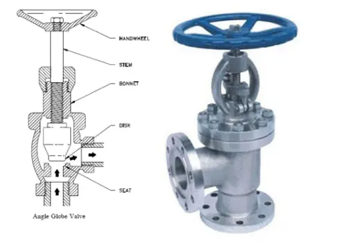
Globe valves are linear motion closing-down valves used to start, stop or regulate the flow using a closure member referred to as a disc. The globe valve disk can completely close the flow path or can be removed entirely. The seat opening changes proportionately with the travel of the disc which is ideal for duties involving flow regulation. Globe valves are most suitable and widely used for throttling and controlling fluid flow and are generally employed in small-size piping.
A globe valve uses a linear motion for moving a disc (closure member) into or out of the seating surface. Globe Valves form a globular-shaped cavity around the port region and hence the name. The disc can be of various shapes and moves perpendicular to the globe valve seat. This disc movement helps in valve opening and closure. Globe valves in general are used for pipes of size 8 inches or less. In this article, we will explore the globe valve types, parts, working principles, functions, symbols, applications, advantages, and disadvantages.
In addition, depending on the design of the seat and disc, the seating load of globe valves can be positively controlled by a screwed stem. The sealing capacity of the globe valve is high. They can be used for on-off duty if the flow resistance from the tortuous flow passage of these valves is acceptable. Some globe valves are also specifically designed for low flow resistance for use in on-off duty. Because of the short travel distance of the disc between the open and closed positions, globe valves are ideal if the valve has to be opened and closed frequently. Thus, globe valves can be used for a wide range of duties.
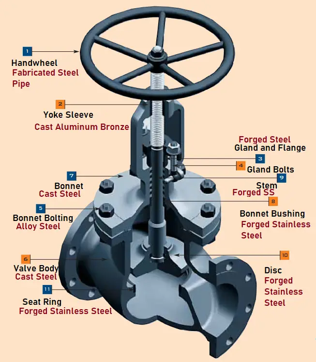
Globe Valve Parts
A typical globe valve constitutes of the following parts:
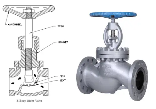
Valve Body (6): Globular shape
Bonnet (7)
Disc or Plug (10)
Stem (9)
Yoke
Gland bushing and flange (3)
Seat ring (11)
Yoke Sleeve (2)
Gland Bolts and Nuts (4)
Handwheel (1): Mechanical Actuator
Back Seat
Pressure Seal Gasket
Packing
Typical Globe Valve
Types of Globe Valve
To meet the varied range of work duties at the lowest cost, numerous variations of globe valves are designed. The three most common types of globe valve configurations available for industrial use are
Tee Pattern (T-Type) Globe valves possess the lowest flow coefficient and a higher pressure drop. In severe throttling services, such globe valves can be used. If the pressure drop is not a concern and throttling is required, the Tee type globe valve will be a good choice.
Wye Pattern Globe valves can be cracked open for long periods without severe erosion. They offer very low resistance to flow. For start-up operations, Y-type globe valves are extensively used.
Angle Pattern Globe valves turn the fluid flow in a perpendicular direction without the use of an elbow. For pulsating flow services, angle-type globe valves are used because of their capability of handling the slugging effect.
Globe Valve Patterns
Types of Globe Valves depending on Body Bonnet Connection
Based on body-bonnet connections the following types of globe valves are available:
Screwed bonnet: Inexpensive, simple design.
Bolted bonnet: most popular and widely used. Need a gasket for body and bonnet joint sealing.
Welded bonnet: popular where no disassembly is required. lighter weight.
Pressure-Seal bonnet: for high-pressure applications, this type of globe valve is used.
Flanged bonnet: Can be designed for any size and operating pressure. However, with an increase in pressure, this type of globe valve becomes heavy and bulky.
Union-ring bonnet: A separate screwed union ring is required to hold the bonnet to the valve body. This type of globe valve construction is usually limited to up to 3 inches in size.
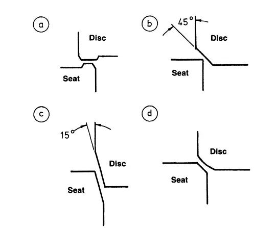
Globe Valve Seating
Globe Valves are provided with either metal seats or soft seat arrangements. To keep the seating stresses uniform, a number of variations of seating design are made. The following figure shows the most frequently employed seating configurations in globe valves.
Common Seating Configurations in Globe Valve
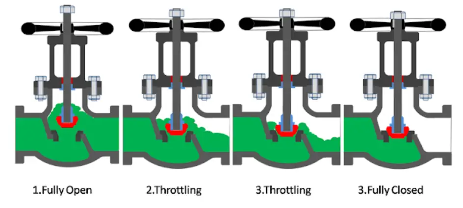
The Function of a Globe Valve
The main function of a globe valve is to start, stop, or regulate the flow. As the globe valve opens the disk moves upwards allowing the fluid to flow proportionally. In an open position, the valve stem rises and popped out at the top. Globe Valve is normally used in smaller sizes; mostly 12 inches or less in sizes. With an increase in the globe valve size, the power required to operate increases. In normal practice, a globe valve works as an on-off valve, but it can be used for throttling purposes as well.
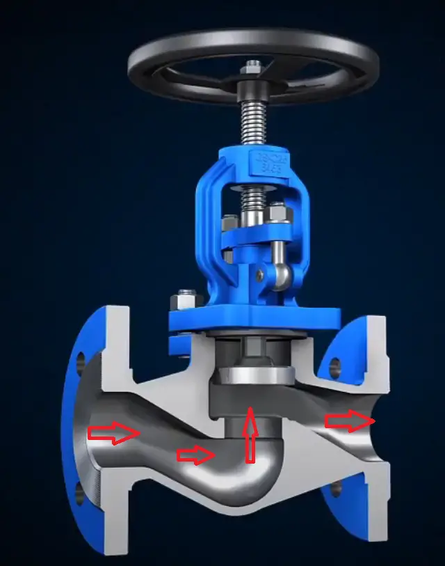
Working Principle of Globe Valve
Refer to the cross-sectional image of the globe valve shown below. A globe valve is comprised of a movable disk and a stationary ring seat in a spherical body. The seat of a globe valve is in the middle of and parallel to the pipe, and the opening in the seat is closed off with the disk. As can be seen from the image, when the handwheel is rotated manually or by an actuator, the disc movement is controlled (lowered or raised) by means of the valve stem. When the globe valve disc seats over the seat ring, the flow is completely stopped.
Globe Valve Working
But when the disk is lifted the flow begins as the upward movement of the disc creates space for the fluid.
Globe Valve Disks
The position of the globe valve disk and seat can be described schematically as follows:
Globe Valve Disc position
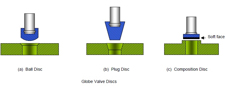
The Disc of a globe valve is made in three basic designs; Conventional Disc (or Ball Disc), Composition Disc, and Plug Type Disc.
Ball Disk:
In the conventional type of disc, the seat and disc construction is made of a ball-shaped metal disc. This possesses a short taper and it easily fits against a flat-surfaced seat in the body. For low-pressure services, this type of globe valve is quite popular and economical. Even though the ball disc is capable of throttling flow, but still primarily used to start and stop the flow.
Composition Disk:
A hard, nonmetallic insert ring is used on the disc of a composition disc design to create a tighter closure. For high-temperature and pressure applications, composition disks are used due to their sufficient resilience and erosion resistance. The composition disc globe valve is basically an improved version of the conventional disk-type globe valve. Composition discs can be replaced or repaired.
Types of Disks of a Globe Valve
Plug Disk:
The plug disc is the best among all three globe valve disk designs and is suitable for throttling services. A long tapered metal plug is made into a plug disc that seats into a cone generating a wide seating surface.
Disc – Stem Configuration
The stem of a globe valve can rotate or not rotate while raising or lowering the disc depending on the design. Accordingly, various disc–stem configurations are available like
Rotating Stem with Integral Disc
Rotating Stem with Non-Integral Disc
Non-Rotating Stem with Integral Disc
Non-Rotating Stem with Non-Integral Disc
Because of the simplicity of design, most globe valves incorporate a rotating stem.
Globe Valve Flow Direction
For low-temperature applications, the flow direction in a globe valve is installed so that pressure acts under the disk. This design helps in easy operation, protects the packing, and eliminates a certain amount of erosive action to the seat and disk faces. Whereas, for high-temperature steam service, globe valves are positioned such that the pressure is above the disk. This will avoid the stem contraction upon cooling that may tend to lift the disk off the seat.
Globe Valve Symbol
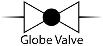
The following globe valve symbol is quite popular in the piping industry. These are used in P&IDs to differentiate a glove valve from other valve types.
Glove Valve Symbol
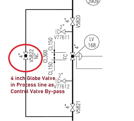
The following image shows the typical globe valve symbol used to denote a bypass valve in the control station.
Globe Valve in Control Valve By-pass
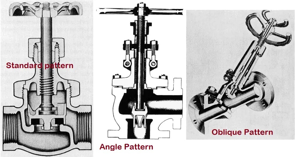
Globe Valve Patterns
Globe Valves are available in three body patterns.
Standard pattern (T-Pattern or Z-Pattern)
Angle Pattern
Oblique Pattern (Wye Pattern or Y – Pattern)
Standard Pattern or T/Z– Pattern globe valves
This is the most common globe valve body pattern. The horizontal setting of the seat allows the stem and disk to move perpendicular to the direction of the fluid flow. This design provides the highest resistance to fluid flow among all of the available patterns. This standard pattern globe valve design has the lowest flow coefficient and the highest pressure drop. For severe throttling services and applications where pressure drop is not of much concern like in bypass lines around a control valve, this type of globe valve is commonly used.
Z-type globe valve diagram
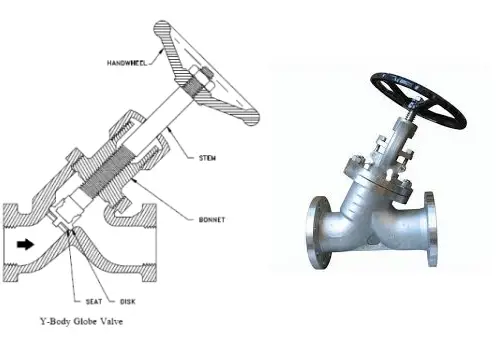
Oblique Pattern or Y–Pattern globe valve
The oblique Pattern globe valve body design is suitable for applications requiring low-pressure drop. Their oblique pattern design reduces the resistance to the flow of the globe valve to a minimum. The seat and stem being angled at approximately 45 degrees, provides a straighter flow path at full opening and offer the least flow resistance.
Y-type globe valve diagram
Angle Pattern globe valve
Angle pattern globe valve body design is manufactured by modifying the basic standard pattern globe valve. The valve ends of this type of globe valve are perpendicular or at an angle of 900, and fluid flow occurs with a single 900 turn. As compared to the oblique pattern globe valves, they have a slightly lower coefficient of flow. For applications having pulsating flow because of their capability to handle the slugging effect, angle pattern globe valves are used.
When a globe valve is required near a pipe bend, the angle pattern globe valve body offers two advantages. First, the angle pattern body provides a greatly reduced flow resistance. Second, the angle pattern design saves the requirement of a pipe fitting and joint.
Angle-type globe valve diagram
Advantages of Globe Valve
The main advantages of globe valves can be summarized as follows:
Good sealing capability.
Moderate to good throttling capability.
Shorter stroke.
Provide a wide range of capabilities as available in tee, Wye, and angle body styles.
Machining and resurfacing the seats are easy.
The globe valve can be used as a stop-check valve by modifying the design slightly.
Disadvantages of Glove Valve
The globe valve disadvantages can be listed as follows:
Higher pressure drops due to many directional changes.
Greater force or power requirement to seat the valve.
Throttling flow under the seat and shutoff flow over the seat.
Applications of Globe Valve
Globe valves can be used in a wide range of services; both low-pressure and high-pressure fluid services. The typical applications of globe valves are:
Bernoulli’s principle provides a relationship between the pressure of a flowing fluid to its elevation and its speed. The conservation of kinetic, potential, and flow energies of a fluid stream and their conversion to each other is dictated by the Bernoulli principle. This principle is widely used in the study of the flow of water, air, or any other fluids having low viscosity. Many real-life engineering problems related to fluid flow can be easily solved by applying Bernoulli’s principle. This is the reason that Bernoulli’s principle is quite popular and studied in engineering and physics. This principle is deduced by Daniel Bernoulli and as per his name, it is widely known as Bernoulli’s principle.
Bernoulli’s Equation
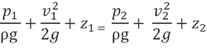
Bernoulli’s equation provides the mathematical basis of Bernoulli’s Principle. It states that the total energy (total head) of fluid along a streamline always remains constant. The total energy is represented by the pressure head, velocity head, and elevation head.
The pressure head signifies the height of a column of fluid and is represented by P/ρg; the Velocity head signifies the kinetic energy and is represented by V2/2g, and the Elevation head signifies the potential energy and is represented by z. So, As per Bernoulli’s equation
(P/ρg)+(V2/2g)+z=Constant
The equation explains that, if an increase in the speed of a fluid occurs, there will be a decrease in static pressure or a decrease in the fluid’s potential energy. For flow inside horizontal pipes, where elevation head z is constant; the velocity increase will cause a decrease in pressure.
Assumptions in Bernoulli’s Equation
The following assumptions are made for deriving the above-mentioned Bernoulli’s equation:
The fluid is ideal and it does not have any viscosity.
Net frictional forces are negligible.
The fluid is moving or flowing through a pipe or channel.
The flow is incompressible and steady.
The is no rotation in the flow.
There is no heat transfer in the streamline.
Derivation of Bernoulli’s Equation
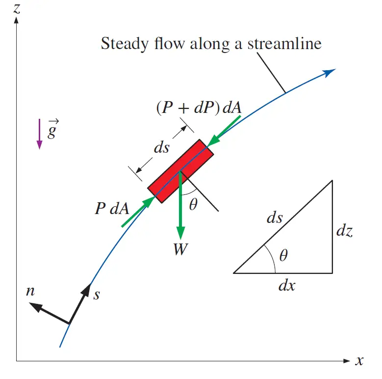
Refer to the image shown below that indicates the motion of a fluid particle of length ds in the s direction.
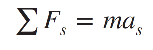
Applying Newton’s second law in that moving fluid particles in a steady flow we get,
Now considering the assumptions mentioned above, the significant forces that will be acting in the s-direction are the pressure and the component of the weight of the particle in the s-direction.
Therefore, we can write the above equation as:
P dA − (P + dP) dA − W sin 𝜃 = mV (dV/ds );
where 𝜃 is the angle between the normal of the streamline and the vertical z-axis at that point, m = 𝜌V = 𝜌 dA ds is the mass, W = mg = 𝜌g dA ds is the weight of the fluid particle, and sin 𝜃 = dz/ds. Substituting we get,
−dP dA − ρg dA ds (dz/ds) = ρ dA ds V (dV/ds)
After simplification, we get
−dP − ρg dz = ρV dV
Now, V dV = 1/2 d(V2) and dividing each term by 𝜌 gives
dP/ρ + 1/2 d(V2) + g dz = 0
Integrating we get,
P/ρ +V2/2 + gz = constant
Dividing by g we get,
(P/ρg)+(V2/2g)+z=Constant
This is the famous Bernoulli equation, widely used in fluid mechanics for steady, incompressible flow along a streamline in inviscid regions of the flow.
Applications of Bernoulli’s Equation
The Bernoulli equation and principle find a wide range of applications in engineering fluid dynamics. This theory is applied to designing aerospace wings and for designing pipes for hydroelectric plants. Bernoulli’s equation is popularly used to:
The following examples of Bernoulli’s principle are widely popular.
Bernoulli’s Equation for Pump Sizing:
The volute in the centrifugal pump casing converts the velocity of the fluid into pressure energy by increasing the flow area. Here the conversion of kinetic energy into pressure energy is according to Bernoulli’s equation.
The pump head requirement is also decided by applying Bernoulli’s equation.
Design of Ejectors:
The conversion of the pressure energy of the motive fluid into the kinetic energy inside an ejector follows the principles of Bernoulli’s equation.
Pressure measuring instrument, Pitot Tube also works following Bernoulli’s principle.
Bernoulli’s equation to design the Automobile Carburetor:
Automobile Carburetors are a good example of Bernoulli’s equation. Bernoulli’s principle is used to meter the airflow inside the carburetor. The faster the air flows, the lower the static pressure, and the higher the dynamic pressure that decides the fuel intake into the airstream.
Working of Siphons:
Widely used Siphons also follow Bernoulli’s equation to evacuate or remove fluids from a container.
Application in Hydro-power Generation:
Hydroelectric engineers decide the water velocity from mountain reservoirs by knowing the elevation changes and using Bernoulli’s Principle.
Bernoulli’s Principle for Generating the Lift Force in Aeroplanes:
The top part of an airplane wing is curved while the bottom part is designed as a flat surface. This results in lower pressure on the top of the wing as compared to the bottom of the wing. This generated pressure difference (according to Bernoulli’s principle) creates the lift force for the plane.
Birds also fly in the sky using the same Bernoulli’s Principle.
Venturi meters are instruments for fluid flowmeasurement. It has a converging section that gives an increase in the flow velocity with a corresponding drop in pressure from which the flow rate can be calculated. The reduction in the fluid pressure that occurs when a fluid moves through a constricted passage is known as the Venturi effect. Venturi meters are widely used wherever there is a need for fluid flow measurement, specifically in water, chemical, and oil industries. Depending on the application and size requirements, industrial venturi meters are constructed in various forms. These versatile instruments are known for longevity, long performance, and reliability. In this article, we will discuss about the following:
Definition of Venturimeter
Venturimeter Diagram and Parts
Working Principle of Venturi meter
Venturimeter Formulas
Co-efficient of Discharge for Venturimeters
Venturimeter Types
Applications, Advantages, and Disadvantages of Venturimeters
Difference between Venturimeter and Orificemeter, and
Many more.
What is a Venturimeter? Venturimeter Definition
Venturimeter is a type of flowmeter that works on the principle of Bernoulli’s Equation. This device is widely used in the water, chemical, pharmaceutical, and oil & gas industries to measure the flow rates of fluids inside a pipe. The pipe cross-sectional area is reduced to create a pressure difference which is measured with a manometer to determine the rate of fluid flow. So, the venturi meter is a differential head type flowmeter that converts pressure energy into kinetic energy.
The principle of the Venturimeter was demonstrated by Giovanni Batista Venturi (Hence the name Venturimeter), But it was first used in practical metering applications by Clemens Herschel. In this article, we will explore the parts, working principles, equations, and applications of the Venturimeter.
Venturimeter Diagram and Parts
A venturimeter consists of four parts:
Cylindrical Inlet Section
Conical convergent Section
Cylindrical throat and
Conical divergent outlet
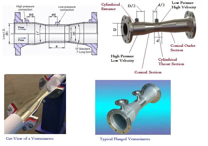
Fig. 1 below shows a typical venturimeter diagram with its parts.
Fig. 1: Typical Venturimeter Diagram with Parts
There are two tappings on the venturi meter for pressure measurement; the upstream pressure tapping is located at a distance of one-half of pipe diameter (D/2) upstream of the convergent entry, while the downstream pressure tapping is located in the throat (d/2) as shown in Fig. 1.
Cylindrical Entrance Section: Venturimeter entrance is a straight cylindrical section with a length equal to 5 to 8 times the pipe diameter.
Convergence Conical Section: In this section, the venturi meter tube diameter gradually decreases. The conical angle is normally 210 ± 20. While the liquid flows inside the venturimeter, the velocity of fluid increases at the expense of a decrease in pressure.
Cylindrical Throat: Throat consists of the minimum venturemeter diameter. In the throat section, the velocity is maximum and pressure is minimum. Normally, throat diameter = 1/3 to 1/4th of inlet pipe diameter.
Diverging Conical section: At this section of venturimeter, the tube diameter gradually increases. So, the pressure is built up again to the original inlet pressure. The cone angle is 5-70. British Standard BS-1042 specifies two conical angles, 5–70 and 14–150 for the outlet cone.
Materials for Venturimeter
Small-size venturimeter are made of brass, glass, or bronze and large venturimeters are made of cast iron, steel, or stainless steel.
Working Principle of a Venturimeter | How Does a Venturi Meter Work?
When a fluid flows through a venturimeter, it accelerates in the convergent section and then decelerates in the divergent section. The pressure difference between an upstream section and the throat is measured by a manometer. Using that differential pressure, applying Bernoulli’s Equation and Contininuity Equitation the volumetric flow rate can be estimated. In the next section, the equations of venturimeter to find the discharge value are discussed.
Venturimeter Equations | Formulas for Venturi Meters
Bernoulli’s principle states the relation between pressure (P), kinetic energy, and gravitational potential energy of a fluid inside a pipe. The mathematical formula of Bernoulli’s equation is given as:
Where,
p= pressure inside the pipe
ρ =density of the fluid
g =gravitational constant
v = velocity
z=elevation or head
a = cross-sectional area of the pipe
d= diameter of the pipe
Suffixes 1 and 2 are used to denote two different areas; 1 denotes the cylindrical inlet section and 2 denotes the throat section.
Now as the pipe is horizontal; there is no difference in the elevation of the pipe centerline; So, z1=z2. Re-arranging the above equation we get the following:
(p1-p2)/ρg = (v22-v12)/2g
(p1 – p2)/ ρg is the difference of pressure heads in sections 1 and 2 which is equal to h that can be measured in the differential manometer. So the above equation becomes
h=(v22-v12)/2g……….eqn. 1
Now applying continuity equations between the same sections 1 and 2, we get
a1v1=a2v2 or v1=(a2v2)/a1
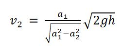
Putting this value of v1 in eqn. 1 and solving we get,
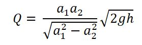
So, the rate of flow through the throat (Q) can be calculated as Q=a2v2; Substituting the above value of v2 we get,
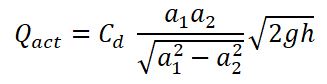
This Q represents the theoretical discharge of Venturi Meter in ideal conditions. But in actual practice, there will always be some frictional loss. Hence, the actual discharge will always be less than the theoretical discharge. So, to calculate the actual discharge, the above Q value is multiplied by Cd, called the Coefficient of discharge of venturimeter. So the actual flow rate through the throat of the venturimeter will be given by the following equation.
Coefficient of Discharge of Venturimeter (Cd)
The coefficient of discharge for Venturimeter, Cd is defined as the ratio of the actual flow rate through the venturi meter tube to the theoretical flow rate. So the venturi meter discharge coefficient is given by:
Cd=Qact/Q
As Qactual will always be less than Qtheoretical due to frictional losses, the value of Cd is always less than 1.0.
The typical range of the discharge coefficient of a Venturi meter is 0.95-0.99 but this can be increased by proper machining of the convergent section. The value of venturimeter discharge coefficient differs from one flowmeter to the other depending on the venturimeter geometry and the Reynolds number.
ISO-5167 code provides the values of venturimeter discharge coefficients. For accurate flow measurement, normally straight length requirement upstream and downstream of venturimeter is specified.
Types of Venturimeters
Normally three types of venturimeters are available:
Horizontal Venturimeter: This type of venturimeter has the highest kinetic energy and the lowest potential energy.
Vertical Venturimeter: This type has the maximum potential energy and the minimum kinetic energy.
Inclined Venturimeter: Both potential and kinetic energy are in between the above two types mentioned.
Applications of Venturimeter | Venturimeter Uses
Venturimeters find wide application in fluid industries. The major application of venturimeters include
Used in Engine Carburetors (Automobile Sector) to measure airflow
Used in process industries (Process and Power Piping Industries) to measure and control process flow.
In the medical industry, blood flow in the arteries is measured by venturimeters.
Measures the fluid flow inside pipelines (Oil & Gas Industries)
Broadly the use of venturimeters are versatile and widely used in the following industries:
Water treatment plant
Chemical processing
HVAC systems
Power Generation systems
Oil and gas industry
Advantages and Disadvantages of Venturimeter
Advantages of Venturimeter:
They provide accurate results.
The accuracy of venturimeter is not dependent on temperature and pressure inside the pipe.
No moving part.
Very low energy loss.
Wide applicability for Water, suspended solids, gases, slurries, chemicals, dirty liquids, etc.
High discharge coefficient and very low-pressure drop.
Venturimeters can be installed in a horizontal, inclined, or vertical direction.
Very little chance of being clogged.
The pressure recovery of venturimeter is very high. The discharge pressure is almost near to inlet pressure.
Disadvantages of Venturimeter:
Venturi meters are large in size; so difficult to install where there is space constraint.
Expensive as compared to other types of flowmeters
Limited range of flow measurement
Not suitable for very small diameter pipes.
Codes and Standards for Venturi Meter
The codes and standards that provide guidelines related to venturi meters are
ISO 5167
ISO 9300
AWWA M33
ISO TR 15377
BS 1042
ASME MFC-8M
ASTM D2458
AGA 9
Installation of a Venturi Meter
Proper installation of a venturi meter is the key to the ideal operation. So, the installation of venturi meters must be performed following manufacturer guidelines. Normally, the following guidelines to be followed while installing a venturi meter in a piping or pipeline system:
The flow direction arrow in the venturi meter should be checked and installed to agree with the direction of the flow.
Flanges at the venturi meter ends should be properly aligned with the piping flanges.
Pipe Support should not be placed on venturi meters.
Installation tolerances should be within industry standards.
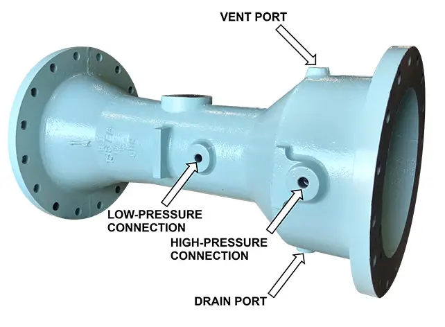
Pressure taps should be oriented horizontally for liquid service applications.
Fig. 2: Venturi Meter Pressure Connections
Venturi meter Upstream and Downstream Pipe Straight Leg Requirement
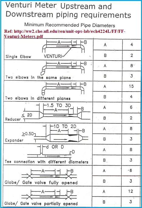
For proper functioning and accurate results, the flow through the venturi meters should stabilize. This calls for minimum straight pipe length requirements upstream and downstream of the venturi meter. Depending on the type of fitting, type of venturi meter, and beta ratio (the throat diameter divided by the inlet diameter) the straight leg requirement varies. The following image (Fig. 2) provides a sample table that provides typical strength leg requirements while installing a venturi meter in a piping system.
Fig. 3: Venturi meter Piping Requirements
Design of Venturimeters
Even though standard classical venturimeter designs need a bit more space, the significant benefit is that their design can easily be modified to fit any requirement. Over the last centuries, venturimeter design has undergone significant changes and two specific designs have contributed in significant impact on Venturi metering; They are:
Modifies Short form Venturimeters, and
Insert Venturi meters.
Modifies Short form Venturimeters: Patented by Dezsoe Halmi, these designed forms of venturimeters are highly accurate, have low headloss, and need no upstream/downstream straight length requirements. Modifies Short-form Venturimeters are more suitable for asymmetric flow patterns due to their overall short length.
Insert Venturi Meters: Insert venturimeter design is somewhat similar to the shape of a Classical Venturi but its profile is entirely inside the pipeline. They utilize a static low-pressure throat tap that sense pressure perpendicular to the axis of the flowing line fluid.
Difference between Venturi meter and Orifice meter | Venturimeter vs Orifice Meter
Venturi meters and orifice meters are both types of differential pressure flow meters that are commonly used to measure the flow rate of fluids in pipes. While they are similar in some respects, they differ in several important ways, including their design, performance characteristics, and applications.
Venturi meters are typically designed with a tapered throat section that gradually reduces the cross-sectional area of the pipe. As the fluid flows through the throat, its velocity increases and its pressure decreases, creating a pressure differential between the upstream and downstream sections of the meter. This pressure differential is proportional to the square of the flow rate and can be measured using pressure gauges or transducers.
In contrast, orifice meters use a flat plate or disc with a precisely measured hole in the center to constrict the flow of fluid in the pipe. This creates a pressure drop that is proportional to the square of the flow rate and can be measured in the same way as with a venturi meter.
Here are some key differences between Venturi meters and orifice meters:
Design: A Venturi meter has a gradual taper to the throat section, while an orifice meter has a sharp-edged disc or plate with a hole in the center.
Pressure recovery: The pressure recovery in a Venturi meter is better than in an orifice meter, meaning that the pressure downstream of the meter returns closer to the upstream pressure.
Accuracy: Orifice meters are generally less accurate than Venturi meters, particularly at low flow rates, where the turbulence caused by the sharp-edged orifice plate can create errors.
Applications: Venturi meters are often used for high flow rates and in systems where pressure drop is a concern, while orifice meters are used in a wider range of applications, including lower flow rates and where cost is a concern.
Installation: Venturi meters require longer straight sections of pipe upstream and downstream of the meter to achieve accurate readings, while orifice meters can often be installed with less straight pipe.
Overall, the choice between a Venturi meter and an orifice meter will depend on the specific requirements of the application, including flow rate, accuracy, pressure drop, and cost.
The major differences between a venturimeter and an orifice meter can be tabulated as follows:
Orifice meters, on the other hand, need relatively lower space.
In venturimeter, the Energy Loss is less.
Orifice meters have comparatively more energy loss.
Venturimeters are quite expensive.
Orifice meters are comparatively cheaper.
High discharge coefficient.
Low coefficient of discharge.
Venturimeters provide High-Pressure Recovery.
Pressure Recovery in the Orifice meter is relatively less.
Venturimeter vs Orificemeter
FAQ on Venturimeters
1. What is a venturi meter used for?
A venturi meter is used to measure the flow rate of fluids in a pipe. It is widely employed in various industries, including water treatment, chemical processing, oil and gas, and HVAC systems. By measuring the pressure difference between the inlet and the throat of the venturimeter, it provides accurate flow measurements, which are essential for process control and optimization.
2. How does a Venturi device work?
A Venturi device works on the principle of the Venturi effect, which states that as a fluid flows through a constricted section of a pipe, its velocity increases, and its pressure decreases. The venturimeter has a convergent section that narrows into a throat and then diverges. Pressure taps are located before and at the throat. The difference in pressure between these points is used to calculate the flow rate of the fluid using Bernoulli’s equation.
3. What is the working principle of the venturi effect?
The Venturi effect is based on Bernoulli’s principle, which states that an increase in the velocity of a fluid results in a decrease in its pressure. As fluid flows through the constricted throat of the venturimeter, its velocity increases, causing a drop in pressure. This pressure drop is measured and used to determine the flow rate of the fluid.
4. Why is it called a venturi?
The device is named after Giovanni Battista Venturi, an Italian physicist who first described the principle in the 18th century. Venturi’s research on the effects of fluid flow through constricted sections of pipes led to the development of this flow measurement device.
5. What is the ratio of venturi meter?
The ratio of a venturi meter typically refers to the area ratio between the pipe’s diameter at the inlet and the throat. This ratio is crucial for determining the meter’s accuracy and performance.
6. What is the ISO standard for venturi meter?
The ISO standard for venturi meters is ISO 5167. This standard specifies the requirements for the design, installation, and testing of venturi meters used for measuring the flow of liquids, gases, and steam. It ensures that the venturi meters meet international standards for accuracy and reliability.
7. What size is a Venturi pipe?
The size of a Venturi pipe varies depending on the specific application and flow rates required. Venturi meters can be designed for a wide range of pipe sizes, from small laboratory setups with diameters of a few millimeters to large industrial pipes with diameters exceeding several meters. The size is typically chosen based on the fluid flow rate and the accuracy requirements.
8. What is the coefficient of Venturi?
The coefficient of a venturi meter, often referred to as the discharge coefficient (Cd), accounts for losses and deviations from the ideal flow. It is a dimensionless number that varies with the design of the venturi meter and the characteristics of the fluid. It is used to adjust the theoretical calculations to match the actual flow measurements. The value of Cd is usually determined through calibration and testing.
9. What is the advantage of venturimeters?
Venturi meters offer several advantages:
High Accuracy: They provide accurate flow measurements with minimal pressure loss.
Durability: They have no moving parts, which reduces maintenance and wear.
Wide Range: They are suitable for measuring a broad range of flow rates.
Versatility: They can measure various fluids, including liquids, gases, and slurries.
Minimal Pressure Loss: Compared to other flow measurement devices, venturi meters exhibit relatively low-pressure drops, which is advantageous for maintaining system efficiency.
Video Tutorial on Venturimeters
The above contents are explained in the following video tutorial on Venturimeters titled “What is a Venturimeter?”