A flexible hose is a type of piping used to connect two distant points to transport or transfer fluid. In Oil & Gas applications, hoses are used when there is a considerable relative movement. A variety of fluids and fluidized solids can easily be transferred through flexible hoses to other locations. These are most commonly known as hosepipes. Along with loading and unloading services in processing plants, these are widely used by homeowners as garden hoses. Normal Flexible hoses are made of non-metals like soft plastic material or synthetic rubber. However, flexible hoses of chemical industries that are designed to absorb pipe movements are made of metallic materials.
Non-metallic Flexible Hoses
Flexible hoses are made by extrusion or vulcanization process. To add strength to the non-metallic flexible hoses, they are reinforced using a crisscrossed grid of fibers combined together through braiding, spiraling, or knitting. These reinforced hoses can be long enough. Basically, flexible hoses have four parts; inner tube, reinforcement, End fittings, and protective outer cover.
Flexible Metal Hoses
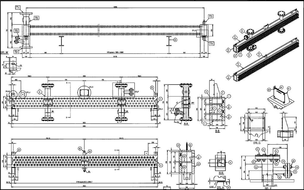
Metallic flexible hoses consist of corrugated tubing, braid, braid collars, and end-fittings as shown below:
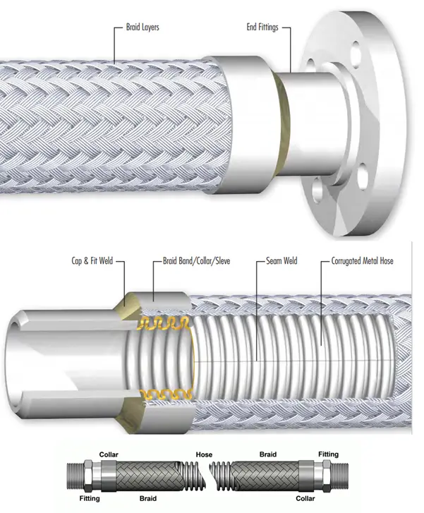
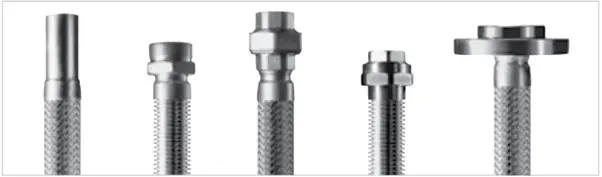
Metallic flexible hoses are available in various end connections like welded pipe ends, flanged ends, threaded ends, tube ends, coupling ends, etc to meet a broad range of application requirements.
Types of Metallic Flexible Hoses
Two types of metallic flexible hoses are widely used in industries.
- Corrugated hoses and
- Interlocked hoses
Fig. 3 below shows the basic construction of corrugated and interlocked flexible hoses.
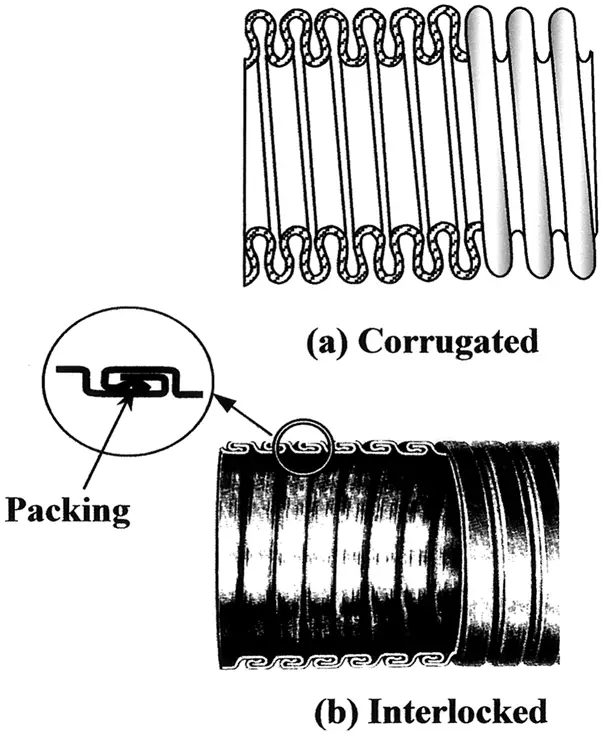
Corrugated Hose:
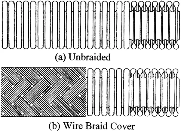
A corrugated hose is constructed with a bellow of very long length. Fundamentally, the behavior of a corrugated flexible hose is the same as the bellow expansion joint. The flexible hose has to resist the hoop pressure stress, but cannot sustain the longitudinal pressure stress. Also, it has a tendency to squirm under internal pressure. To resist the longitudinal pressure stress and prevent squirm, corrugated hoses are often constructed with braids wrapping around the outside surface as shown in Fig. 4. The braided cover also protects the corrugation from scratch and wear. The braided hose, similar to a tied expansion joint, cannot accommodate any axial movement. On the other hand, the un-braided hose can sustain very small internal pressure.
Due to the lack of a limiting mechanism, a corrugated flexible hose is prone to abuse. It should not be bent beyond its acceptable range. For braided hoses, the situation is even more critical.
As the corrugations are not visible from the outside, a braided hose does not show immediately when damaged. Therefore, for manual handling in such situations as loading/unloading and switching operations corrugated hose is not suitable. The corrugated flexible hose has a continuous metal wall thus making it pressure-tight. It is suitable for handling any type of gas and liquid as long as it is compatible with the hose material.
Interlocked Hose:
An interlocked hose is constructed with links that are kept tight with packing material. There are clearances provided between the links that afford the capability of accommodating some axial movement. As the hose is being bent, the clearances gradually close. The hose becomes stiff and cannot bend any further at a certain point when the clearances are completely closed. This sudden stiffening effect serves as a warning to the handler, preventing the interlocked hose from being over-bent. This automatic warning feature makes the interlocked hose especially suitable for manual handling.
The packing mechanism at the interlocked links does not offer a perfect seal. Therefore, the interlocked hose is satisfactory for carrying low-pressure air, steam, and water, but is generally not suitable for conveying gases and “searching” liquids such as kerosene and alcohol. The outside of the interlocked hose is relatively smooth, making it easy to handle without any covering.
Stress Analysis Consideration for Flexible Hoses
The flexible hose assembly is normally not analyzed. In most situations, the end displacements from piping or equipment connections are calculated from pipe stress analysis software and those values are transferred to the vendor for their consideration. Accordingly, the hose length and installation space are determined.
Pipe Supporting for optimum flexible hose working
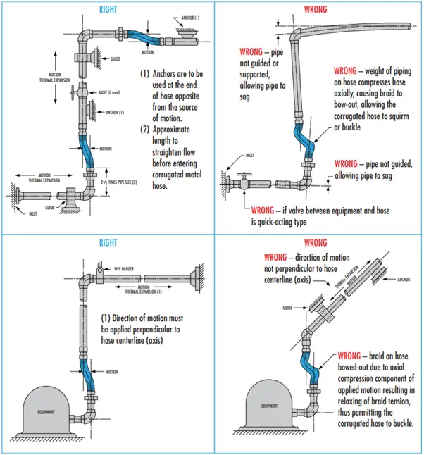
A piping system that utilizes a flexible metal hose to absorb pipe movement must be properly anchored and guided to assure correct functioning and maximum service life of the metal hose assembly. The following basic principles should be observed:
- The direction of pipe motion must be perpendicular to the centerline (axis) of the hose.
- To prevent torsional stress, the pipe shall be anchored at each change of direction where a flexible metal hose is employed. Typical examples of correct and incorrect guiding are shown below in Fig. 5.
Installation considerations for Flexible Hoses
Flexible Hoses are used to accommodate piping and equipment displacements. Hoses are extremely flexible, installations are very easy. However, a few general precautions should be exercised during installation to avoid hose failures.
- The hose should not be subjected to twisting; Also, the installation should be such that flexing takes place only in the plane of bending.
- The length of the hose should be sufficient to accommodate the offset and movement
- The installation space should be adequate to accommodate the length.
- Sharp bends should be avoided while installing flexible hoses. The Technical Data Section of the vendor catalog should be followed to maintain the minimum centerline bend radius for intermittent flexing.
While installing flexible hoses, the allowable minimum bend radius is the most fundamental limitation. For interlocked hoses, the limiting radius depends largely on the clearances between links. It has less to do with stress and fatigue, so it generally has only one limiting radius for all applications. For corrugated hoses, on the other hand, the limiting radius depends on the stress at the corrugations.
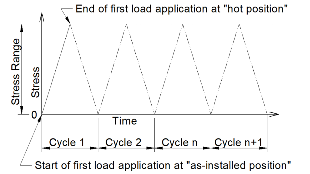
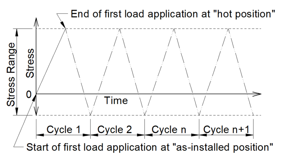
For pressure hoses with braided reinforcement, the corrugation stress comes mainly from the bending of the hose. Therefore, the corrugation stresses can be controlled by setting a limitation on the bending. In other words, the installation is acceptable if the hose is not bent beyond the limiting radius. Similar to the situation discussed in the bellow expansion joint, the mode of failure of the hose corrugation is due to fatigue. Therefore, the bend radius limitation depends also on the number of operating cycles expected. Most manufacturers provide two limiting radii, one for static applications involving a one-time fit-up installation, and the other for operational movement involving many cycles of intermittent flexing. The whole design and installation process actually ensures that this minimum radius is maintained during the initial layout and throughout the operation.
Factors for Metallic Flexible Hose Selection
The main factors that should be considered while selecting a flexible hose are:
- Design and maximum working pressure.
- Maximum service temperature of the material.
- Fluid flow velocity
- Axial, Angular, Offset, Radial, and unpredictable displacements if any.
- Vibration tendency if any.
- Required cycle/service life.
Materials for Metallic Flexible Hoses
The most common materials used for metallic flexible hoses are:
- Carbon Steel
- Stainless Steel
- Bronze
- Monel
- Inconel
- Copper
- Brass
- Aluminum
- Aluminized Fiberglass
- Silicone coated fiberglass
Depending on the operating service temperature range, these materials are decided.
Codes and Standards for Flexible hoses
The codes and standards used for design guidance are listed below:
- The Society of Automotive Engineers (SAE) SAEJ513: Requirements for Hydraulic hoses.
- ISO 10807: Corrugated flexible metallic hose assemblies for the protection of electrical cables in explosive atmospheres
- Interlocked hoses are manufactured from a helically (spiral) wound and overlapping profiled strip in accordance with BS EN ISO 15465.
- Pressure equipment directive (PED 97/23/EG)
- DIN EN 14585-1: Pipework-Corrugated metal hose assemblies for pressure applications
- EN 12434: Cryogenic vessels – cryogenic flexible hoses
- DIN EN ISO 10380: Pipework-Corrugated metal hoses and metal hose assemblies
- ISO 10806: Pipework – Fittings for corrugated metal hoses
- ISO 21969: High-pressure flexible connections for use with medical gas systems
- EN 2827: Hose assemblies of stainless steels for chemical products
- DIN 3384: Stainless steel flexible hose assemblies for gas applications-safety requirements, testing, marking
- EN 14800: Corrugated safety metal hose assemblies for the connection of domestic appliances using gaseous fuels
Applications of Flexible Hoses
Specific applications of flexible hoses include the following:
- to water plants or to convey water to a sprinkler (Garden hose).
- to water crops in agriculture (tough hose) for drip irrigation.
- to convey water to the site of the fire for firefighting service (fire hose).
- to carry air from a surface compressor (Air hose) or from air tanks.
- In chemistry and medicine, flexible hoses are used to move liquid chemicals or gases around.
- A fuel hose carries fuel.
- to move liquids under high pressures in the oil industry.
- For Heat Tracing
- For Auto heater tubing, Ventilating ducting, Moderate suction lines, Automotive exhaust, Dust collecting Ducting, Air Blower ducting, Wiring conduit, Refrigeration tubing armor, Carburetor air intake, hot ash granulate, etc
Data required for ordering a flexible hose
The following data must be supplied while ordering a flexible hose:
- Size of hose and connected fittings
- Design & Operating temperature
- Design and Operating Pressure
- Displacements
- Service and Application
- End-fitting attachment type
- Developed Assembly length
All flexible hoses are subject to aging and their performance deteriorates after a number of years. So flexible hoses must be inspected following a company-approved inspection plan or as per manufacturer recommendation.