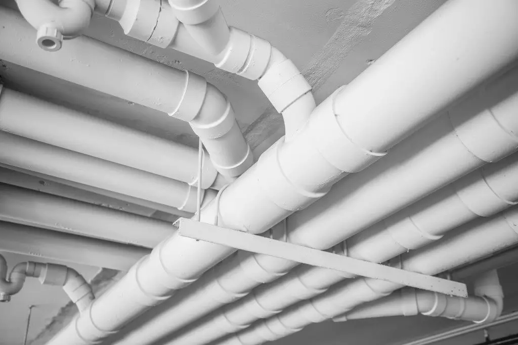
PVC piping is one of the versatile types of plastic piping. PVC pipes have been in use for many years servicing a lot of applications in various market sectors. These pipes are made out of a material which is known as polyvinyl chloride. PVC pipes possess good strength and are highly durable with very good corrosion resistance properties. They are economical, robust, and come in various sizes with a range of pipe fittings. They can be used for both warm and cold water applications. PVC piping is easily available in the market. In water distribution and sanitary applications, PVC piping accounts for more than 60% of the market share. Fig. 1 shows a typical application of PVC Piping in Building Services.
What is PVC Pipe used for?
PVC pipes are used for manufacturing sewage pipes, irrigation, and water mains. PVC pipes possess very long-lasting properties, they are easy to install, strong, lightweight, durable, and easily recyclable hence making them cost-efficient and sustainable. The smooth surface of PVC pipes encourages faster water flow due to a low amount of friction as compared to metallic or concrete piping. These pipes can also be manufactured to different lengths, diameters, and wall thicknesses according to international standards such as DIN 8061 and ASTM D1785. Some other typical applications include:
- Fire Sprinkler Piping
- Radiant Floor Heating
- Piping inside a Swimming Pool
- Chilled Water Systems
- Ice Melting
PVC Piping Schedule
PVC piping is available in different sizes and schedules, denoted by the abbreviation “SCH” followed by a number (e.g., SCH 40, SCH 80). The schedule indicates the wall thickness and pressure rating of the pipe. The higher the schedule number, the thicker the pipe wall and the higher the pressure it can handle. SCH 40 is the most common schedule for general-purpose applications, offering a balance between strength and cost.
How Are PVC Pipes Made?
Chemical Reaction:
These pipes have their origin in the chemical gas known as vinyl chloride. This vinyl chloride is exposed to the sunlight creating a chemical reaction which is known as polymerization which turns into a whitish solid material. In achieving the shape and solidity of a PVC pipe, chemicals are introduced to one another. The natural gas is heated to create ethylene. This process is known as cracking. Then sodium chloride is formed using electrolysis which results in chlorine and sodium hydroxide.
Molecular bonding:
Vinyl chloride monomer is made by introducing chlorine and ethylene. Molecules are then bonded from each molecule’s end resulting in a long chain of PVC polymer. Hence, plastic is created. This polymerized plastic which is known as thermoplastic PVC powder is melted and molded into the piping. This results in a tube of PVC plastic. Due to the chemical process, PVC becomes very solid and rigid and is less likely to break during earthquakes and can therefore withstand pressures that any metals cannot tolerate which is why polyvinyl chloride (PVC) is the preferred material used for plumbing and underground wiring.
Manufacturing of PVC Piping
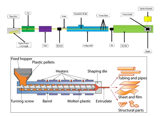
PVC pipes are manufactured using a machine called an extruder in sizes as small as 16mm and large as 630mm. The PVC plastic is being routed through a double screw stem extruder or a conical twin screw. The wall thickness of the PVC hose is determined by molding. A PVC pipe extruder helps in making the diameter of the pipe. The standard PVC pipe extruder has a production speed of about twenty meters per minute. The hose runs through a vacuum pump. At the end of the assembly line, a ring-cutting machine is employed to divide the PVC pipes into sections of individual pipes which are then cooled and racked. The completed PVC pipes are sent to the warehouse for labeling, final inspection, and shipping.
UV resistance of PVC piping
The PVC pipe undergoes surface oxidation and exposure to sunlight. The pipe changes its color from gray to white which becomes more susceptible to impact damage but the strength of the piping is not reduced. By applying a thick coating of latex paint, UV protection can be provided.
Heat Tracing of PVC piping
To maintain a constant elevated temperature, heat tracing of PVC piping is required. The tracing is known as electric tracing. The pressure-temperature rating of the piping system should be more than the maximum heat trace temperature.
Supporting PVC Piping Systems
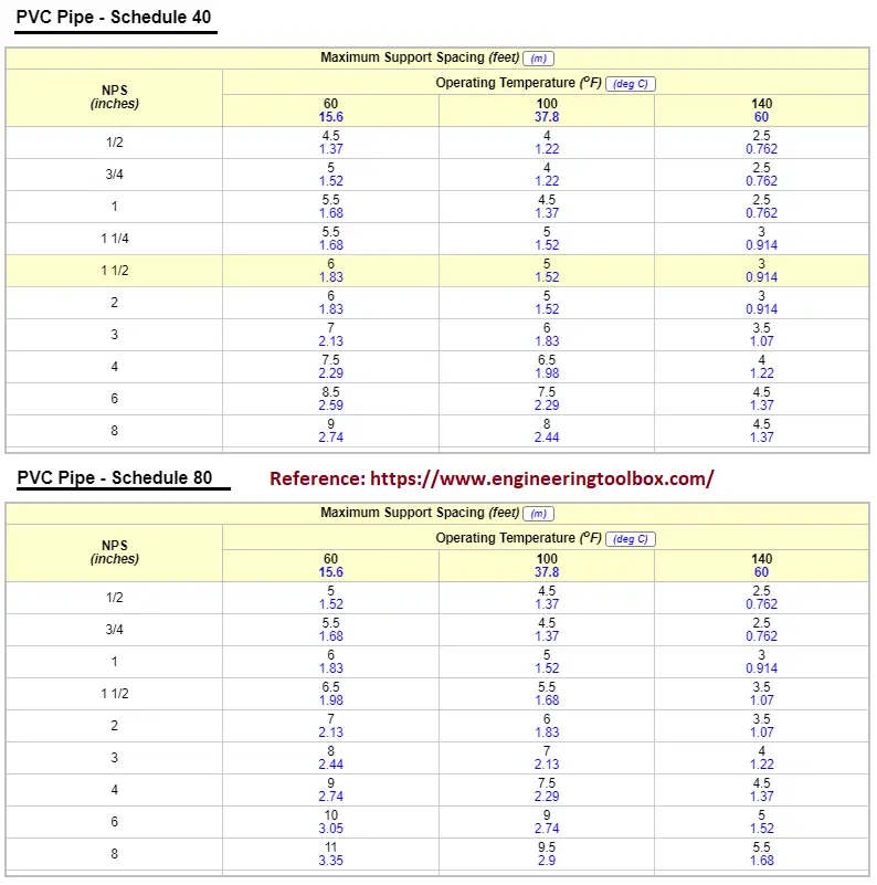
Pipe saddles that are cut from PVC pipe are used at support locations. It should not rest directly on steel. The supports must be provided close to the inline items like valves. The piping connected to the vibrating equipment such as pumps should be isolated by using Teflon or rubber expansion joints. Fig. 3 below shows the typical support spacing for PVC piping systems.
PVC Piping Fittings
To help in directional change, branch connection, size change, etc. of PVC pipe routing, a long list of commonly used PVC piping fittings is available.
Tees:
These are PVC pipe fittings with three ends, one on the side at a 90-degree angle and two in a straight line. They can connect two lines into one main line. PVC tee connections are often used for PVC structures. These are extremely versatile fitting which is some of the most used parts in plumbing. Tees have slip socket ends but threaded versions are also available.
Elbows:
For the piping system to get a turn (directional change), you will need to bend the pipeline around with PVC elbows. These elbows are most commonly available at 90-degree and 45-degree angles. Most elbows have slip socket ends but threaded versions are also available.
Crosses:
This is a slightly less common type of PVC piping fitting that joins a four-pipe section. Crosses have four slip connections that meet at a 90-degree angle thereby forming a plus shape. These crosses are usually used in building frameworks out of PVC pipe. They are used to divide fluid flow in various directions.
Couplings and Unions:
Couplings are the most simple and inexpensive type of PVC pipe fitting. Couplings are small parts that connect one part to another, permanently, that is, they can connect pipe to pipe and pipe to fittings. These are available in female threaded or slip ends depending on the requirement.
Unions connect things but are not as permanent as couplings and can be taken apart. They are used in building temporary structures like tent supports and can be taken apart when the structure is not needed. It has a ring in the center separating the two ends from each other which allows easy maintenance and deconstruction.
Caps and Plugs:
The job of a PVC cap is to stop the flow. Caps are provided at the end of a pipeline that is not connecting to another pipe. The purpose of the cap is to stop a pipeline that is planned to expand later or easy access to the system when needed. Caps also add a finished look to a pipe. They go around or outside of the pipe so as to have a socket or female threaded end.
Plugs are also like caps but they stop the flow in a fitting instead of stopping the flow in a pipe. Because of this, they go inside the fitting which means they have a male threaded end.
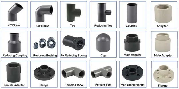
Adapters (Female and male):
Adapters are also known as reducing couplings that are versatile fitting. These are designed to change the pipe’s end type which allows it to connect to fittings and pipes of many sizes. They can have slip socket ends or threaded ends to connect to different pipes and fittings. They can be male or female-threaded as well as a socket.
Bushings:
They are like adapters but focus on connecting pipes of different diameters. They are threaded fittings which makes them apart from other types of fittings which in turn makes maintenance and pipeline customization a lot easier. They are often seen in landscaping applications due to their better performance with water fittings than metal which may cause rust.
Nipples:
In some situations, two female ends in a PVC system have to be connected. The PVC pipe fitting in this job is a nipple. Fitting with two male threaded ends is a nipple. This type of fitting requires a tight fit and is mostly made with schedule 80 PVC; however, they are still compatible with 40 scheduled parts.
Flanges:
These are the type of PVC fittings that allows the attachment of accessories and other items to the pipe. Increases the strength of the pipe. It is a disc-like fitting creating a tight seal by pressing two surfaces together with bolts, edges, and clamps. Mostly bolts are used to join two surfaces. They are available in threaded or slip ends. They are made with schedule 80 PVC because of the strength requirement of the flanges.
PVC Piping Joining Methods
The following joining methods are used for joining two PVC pipes.
- Solvent Welded Joints
- Flanged Joints
- Threaded Joints
Applicable Standards for PVC Piping
The below-listed PVC piping standards are widely used as the design guide for PVC Piping systems.
- ASTM D1785 -Standard Specification for Poly Vinyl Chloride (PVC) Plastic Pipe, Schedule 40, 80, and 120
- ASTM D2241 -Standard Specification for Poly Vinyl Chloride (PVC) Pressure-Rated Pipe (SDR Series)
- ASTM D2672 -Standard Specification for Joints for IPS PVC Pipe Using Solvent Cement
- ASTM D2729 – Standard Specification for Poly Vinyl Chloride (PVC) Sewer Pipe and Fitting.
- ASTM D2464 -Standard Specification for Threaded Poly Vinyl Chloride (PVC) Plastic Pipe Fitting, Schedule 80
- ASTM D2466 -Standard Specification for Poly(Vinyl Chloride) (PVC) Plastic Pipe Fittings, Schedule 40
- AWWA C605 -Underground Installation of PVC and PVCO Pressure Pipe and Fitting
- ASTM F441- Standard Specification for Chlorinated Poly(Vinyl Chloride) (CPVC) Plastic Pipe, Schedules 40 and 80
- ASTM D2665 -PVC drain, waste and vent pipe, and fittings
- EN 1329 – PVC piping for soil and waste discharge – Dimensions
- EN 1401 – PVC piping systems for non-pressure underground drainage and sewerage
- EN 1453 – PVC piping with structured-walls
PVC vs. Carbon Steel
The main property differences between PVC and Carbon steel are listed in the following table.
| Property | Unit | Carbon Steel | PVC |
| Density | kg/m³ | 7860 | 1550 |
| Coefficient of Thermal Expansion | in/in °F x 105 | 0.06 | 3 |
| Thermal Conductivity | BTU/hr/ft2/°F/in | 290 | 1.2 |
| Modulus of Elasticity @ 73°F | psi x 105 | 290 | 4.2 |
| Tensile Strength | psi | 60,000 | 7,940 |
| Working Stress @ 73°F | psi | 20,000 | 2,000 |