Pipe Weight Calculation is a very important process in piping engineering. Pipe weight is directly related to its thickness (Pipe Schedule). The more the pipe thickness or pipe schedule, the more will be the pipe weight. The more the pipe weight, the more will be its rigidity and less flexibility. More pipe weight means more cost of procurement. More pipe weights add more loads on the pipe supports requiring more robust structural member requirements. So, we can say pipe weight is related to overall plant cost in some way. In this article, we will explore pipe weight calculation formulas and methodologies.
Calculating pipe weight is quite simple and fast. The mathematics behind the pipe weight is very easy. The steps and formula for pipe weight calculation are explained below:
Pipe Weight Calculation Formula
To calculate the mass of any object we can use the following formula
Mass (M)= Density (D) X Volume (V) …(eqn. 1)
Pipe weight is also calculated using the same equation. Pipe weight is normally expressed in Pipe Weight per meter of length or Pipe Weight per foot of length. Also, there are two other terms associated with pipe weight calculation. These are
Empty Pipe Weight Calculation and
Water-Filled Pipe Weight Calculation.
Empty Pipe Weight Calculation
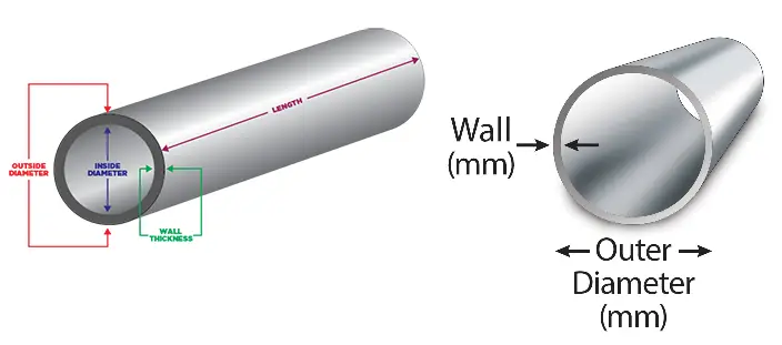
Empty pipe weight means pipe weight without any content inside it. So, it is the weight of the metal present in the pipe. Refer to Fig. 1 below:
Fig. 1: Reference image for Pipe Weight Calculation
So following eqn. 1 above we have to calculate the volume (V) of the pipe first and then we have to multiply the calculated volume by pipe material density (D) in a consistent unit. To calculate the volume of the pipe we need the following parameters:
Pipe Thickness (T) (Obtained from ASME B36.10M / ASME B36.19M), and
Length of Pipe (=1 as pipe weight is expressed in pipe weight per unit length)
The inside diameter (ID) of the pipe can easily be calculated as ID=OD-2T
Pipe Metal Cross Section is calculated as Π (OD2-ID2)/4
The volume (V) of the pipe is calculated as V=Pipe metal cross-sectional area X length of pipe = {Π (OD2-ID2)/4} * 1
CS Pipe Weight Calculation in Kg/m
Let’s calculate the weight of a 6-inch CS pipe with Sch. 40 as pipe thickness. From ASME B 36.10M
Pipe OD=168.3 mm
Pipe Thickness=7.11 mm
Hence, ID=168.3-2*7.11=154.08 mm
Metal Cross Sectional Area=(Π)*(168.32 – 154.082)/4=3600.4565 mm2
So volume for a unit length of pipe=3600.4565 * 1= 3600.4565 mm3 =(3600.4565/1000000) =0.0036004565 m3
So now we have to multiply this volume by CS pipe density (7850 kg/m3) to get the actual weight of 1 m of pipe length.
So the Metal weight of 1 m of Pipe length=0.0036004565*7850=28.26358356 Kg.
To calculate the pipe weight for lengths more than 1 meter, simply multiply the above value by the actual length of the pipe.
Similarly, we can calculate an empty pipe weight per foot of length by considering all the above values in a consistent FPS unit system.
Water-Filled Pipe Weight
Water-filled pipe weight is required to calculate the loads during hydro testing. For the structural supporting design of non-critical lines, pipe loads are calculated or approximated based on water-filled pipe weight.
To calculate the content (water) weight inside the pipe we have to multiply the water density (1000 Kg/m3) with internal pipe cross-sectional volume 1*(Π * ID2)/4.
For the above pipe under consideration, the internal pipe cross-sectional area=Π*154.082/4=18645.86008 mm2=18645.86008/1000000=0.01864586006 m2
So the weight of water content inside the pipe per meter of length=1000*0.01864586006=18.64586 Kg/m.
Now add this content weight with the metal pipe weight to get the total water-filled pipe weight. So,
Water-filled Pipe Weight (Kg/m)=Weight of empty pipe (Kg/m)+ Weight of Content (Kg/m)
In the above example, Water filled pipe weight=28.26+18.65=46.91 Kg/m
By simply multiplying the above value (46.91 Kg/m) by the actual pipe length you can calculate the water-filled pipe weight in Kg.
Pipe Weight Calculator
I have prepared one Pipe weight Calculator in kg/m using the above-mentioned steps and attached it here for your consideration. The metric unit system is used in the Pipe Weight Calculator excel-sheet. Simply, input your data in yellow highlighted boxes and get the actual calculated values at ease.
You can download the pipe weight calculator by clicking the download button shown below.
The following inputs will be required for using the above pipe weight calculator or any other online pipe weight calculator:
Pipe Outer Diameter
Pipe Thickness
Density of Pipe Material
This Pipe Weight calculator can be used to calculate the weights of any piping material by changing the pipe density to the corresponding pipe material density. So Steel pipe weight, Cast iron pipe weight, PVC pipe weight, Copper pipe weight, GRE Pipe Weight, Aluminum Pipe Weight, etc. can easily be calculated using the attached Pipe Weight calculator.
The above-mentioned pipe weight calculation steps are suitable for round pipes. However, as pipes are available in square and rectangular shapes, the methodology for pipe weight calculation for square or rectangular pipe will be different in the way the metal cross-sectional area will be calculated. However, the basic pipe weight calculation equation as mentioned in Equation 1 will still be valid.
Density of Common Pipe Materials to Use in the Pipe Calculation Formula
As you can see, pipe density is one of the most important parameters used in the calculation of pipe weight. Table 1 below provides the density of some of the common pipe materials as a ready reference
Pipe Material
Approx. Density (Kg/m3)
Pipe Material
Approx. Density (Kg/m3)
Carbon Steel
7850
Bronze
8800
Stainless Steel
7700
Titanium
4540
Aluminum
2700
Cast Iron
7000
Brass
8600
Nickel
8900
Copper
8920
PVC
1450
Table 1: Density of Common Pipe Materials in Kg/m3
Pipe Weight Calculation for Square and Rectangular Pipes
For a square pipe with a length of side A and thickness t, the metal cross-sectional area will be {A2-(A-2t)2}. Once you calculate the metal cross-sectional area, multiply it by the pipe material density to find the weight per unit length of the square pipe.
In a similar way, the metal cross-sectional area for a rectangular pipe with length A, width B, and thickness t can be calculated as [A*B-{(A-2t)*(B-2t)}]. So, once it is found, multiply with pipe density to get pipe weight per unit length of rectangular pipe.
Steel Pipe Weight Chart
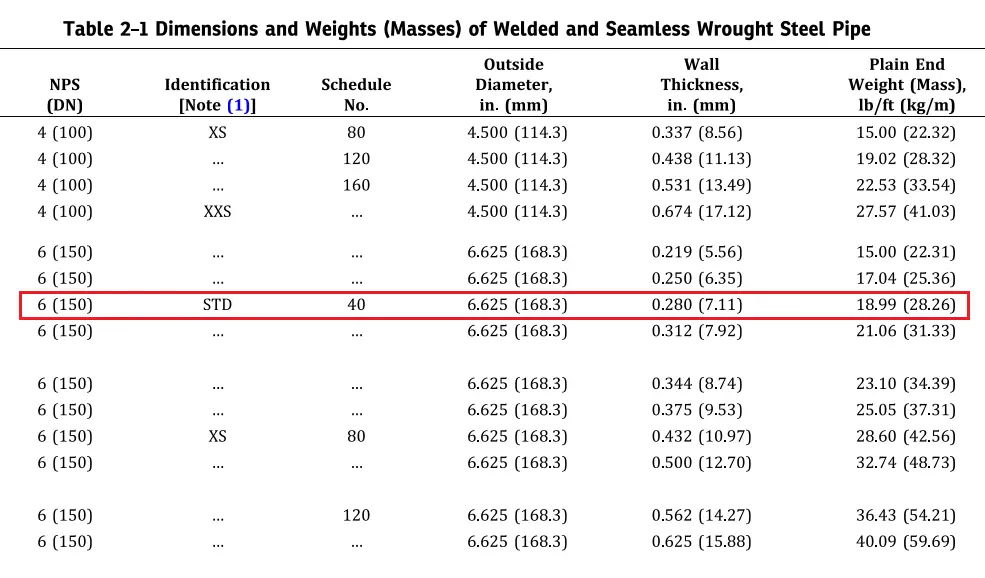
For Carbon Steel and Stainless Steel pipes, the pipe weight per foot or pipe weight per meter of length can easily be taken directly from the Steel Pipe Weight Chart Provided in ASME B36.10M (For Carbon Steel) or ASME B36.19M (For Stainless Steel).
Those two ASME codes provide the Steel pipe weights directly in their tables as pipe weight per foot or pipe weight per meter of length. Part of the table from ASME B36.10M for a 6-inch line that we considered above as an example is produced here to explain the chart.
Fig. 2: Pipe Weight Chart from ASME B 36.10M
As you can see, the empty pipe weight that we calculated for the 6-inch Sch. 40 pipes matches exactly the value provided in the above ASME Code.
However, the above steel pipe weight chart provides only the empty pipe weight value directly. Water-filled pipe weight you have to manually calculate using the above procedure.
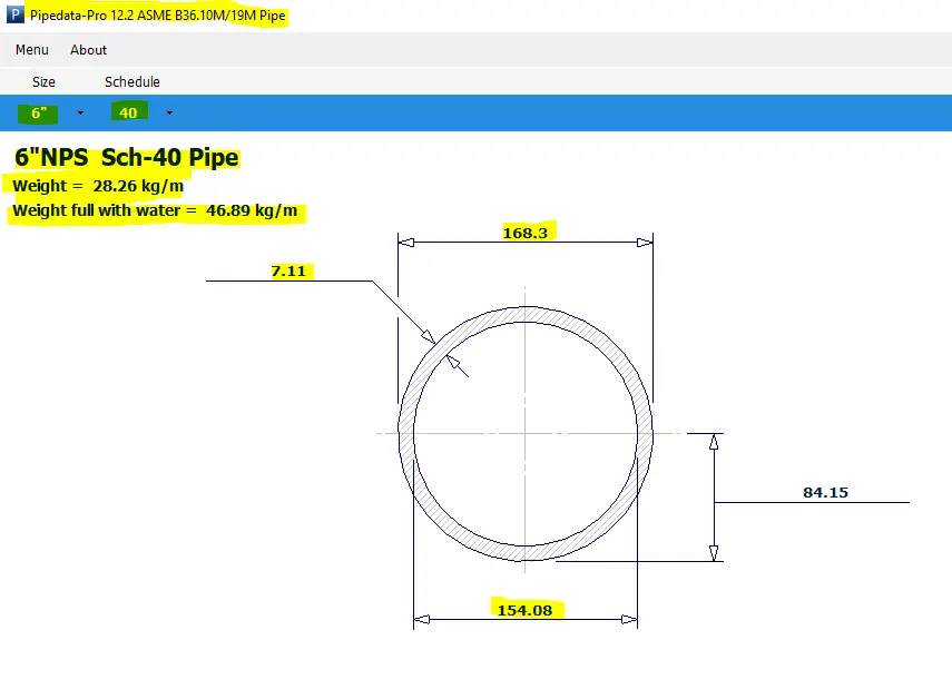
Pipe Weight Calculation using Pipedata-Pro
Both Empty pipe weight and Water-filled pipe weight can easily be obtained if you have Pipedata-Pro software. That software directly gives the pipe weight values of all pipe sizes corresponding to pipe thicknesses. Fig. 3 shows the sample pipe data-Pro Screenshot for the 6-inch Sch. 40 pipes that we considered in our pipe weight calculation.
Fig. 3: Pipe Weight Data as per Pipedata-Pro
The above values show the pipe weight in Kg/m. However, You can easily change the unit if you need data for Pipe weight per foot.
Video Tutorial on Pipe Weight Calculation
The following video tutorial clearly explains all the steps required for pipe weight calculation
How do you find what is the weight of your round pipe?
To calculate the weight of your round pipe, Follow the below-mentioned steps
Step 1. Find the volume of the pipe using the following equation; volume = 0.785398 × [(Pipe Outer diameter)² – (Pipe Outer diameter – 2*thickness)²] × length Step 2. Multiply the pipe material’s volume calculated in step 1 by the pipe material density. Hence, Pipe weight = volume × density
Scaffolding Definition: Types, Parts, Design, Materials, and Hazards of Scaffolding
The term Scaffolding is related to construction and education. In education, scaffolding means breaking the complete learning into small chunks and learning easily using various tools, techniques, and structured ways. However, in the context of this article, we are interested in exploring the term scaffolding with respect to the construction industry. Let’s start with the scaffolding definition.
Scaffolding Definition
During construction, maintenance, or repair work, to support the work crew and materials, temporary structures are built. These temporary structures are called Scaffolding. Scaffolding helps in access at heights and is widely used in all types of construction works. This impermanent structure works as a platform to support the working class to perform its construction activities. As scaffolding involves work at height, it is designed following safety regulations to reduce hazards. Surveys show that a major percentage of accidents in construction industries are directly or indirectly related to scaffolding. So, the scaffolding contractor and scaffolding workers should perform their duties with the utmost care. High-quality materials should be used for scaffolding design.
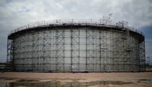
Scaffolding for Tank Construction and Erection
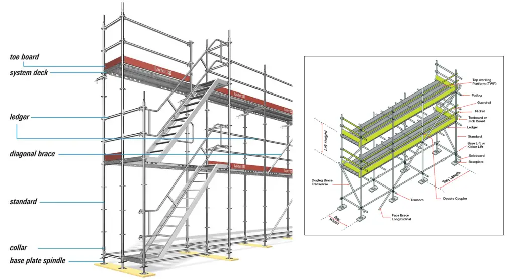
Scaffolding Parts or Components
The major components of scaffolding are as follows:
Standards: Perpendicular tubes that transfer the weight load to the baseplates. To increase the height of scaffolding, standards are connected using pins and socket joints.
Ledgers: Flat horizontal tubes that join between the standards. Ledgers connect multiple bays. Ledgers decide the height of the working platform.
Transom or Bearer: Transoms are used to support standards and they are at the right angles to the ledgers. Transoms define the bay width
Scaffolding Tubes: Steel or Aluminium tubes are used in scaffolding.
Couplers: Fittings to hold tubes together. They are of three types; Putlog Coupler, Swivel Couplers, and Right Angle Couplers.
Diagonal Braces: Strengthen the basic structure to carry more loads.
Boards: Steel, Aluminium, or wooden boards that provide the working area.
Adjustable Base Plates
Guard Rails
Decks or planks
Toe Boards
Putlogs: Putlogs are transverse members that are placed on one end on ledgers and the other ends at right angles on the wall.
Basic Scaffolding Parts
Scaffolding Types
Depending on the type of construction and its requirements to meet various job applications, the Scaffolding structure varies. Broadly, the following scaffolding types are used in the construction industry:
Cantilever Scaffolding
Trestle Scaffolding
Single Scaffolding
Double Scaffolding
Steel Scaffolding
Suspended Scaffolding
Kwikstage Scaffolding
Cantilever Scaffolding
Cantilever scaffolding is widely used where the ground surface is not suitable for setting up conventional scaffolding. Cantilever Scaffolding or needle scaffolding is highly effective when maintenance or construction is needed at great heights or when the project has space constraints. A group of cantilever or needle beams is used to reinforce cantilever scaffolding. Cantilever scaffolding is also known as Single frame scaffolding.
Typical Cantilever Scaffolding
A cantilever scaffolding normally constitutes of the following components:
A Platform
Toe Boards
Protective rails
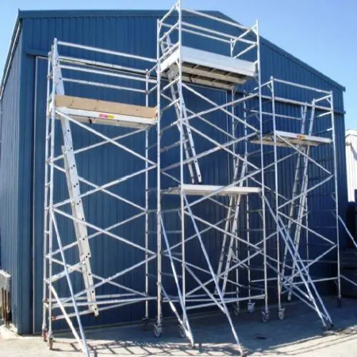
Trestle Scaffolding
Trestle Scaffolding is a highly popular movable scaffolding that can be used up to a height of 5 m. They are fitted with wheels and can be transferred from one place to another very easily. They are used for light-duty work, normally for indoor work.
Trestle scaffolding
Single Scaffolding
Single Scaffolding is made of only one row. A series of vertical members are fixed into the ground parallel to the structure being made. Normally, a single scaffolding is used for building construction. This is also known as the brick layer’s scaffolding.
Double Scaffolding
Double scaffolding is much stronger than single scaffolding. They are also popular as independent scaffolding as two rows of scaffolds is put together that create an independent strong structure. Double Scaffolding is commonly used in stone masonry.
Single and Double Scaffolding
Steel Scaffolding
Steel scaffolding is costly scaffolding but provides greater strength and durability and more resistance. In the process and power piping industries, steel scaffolding is widely used. As the name denotes, the material used is steel in steel scaffolding which can be erected and dismantled quickly. Steel scaffolding is suitable and safe for working at great heights. For big construction works steel scaffolding is preferred over other types.
Suspended Scaffolding
As the name says, these scaffoldings are suspended using ropes or chains from overhead structures. Mainly used for repair and painting works, suspended scaffolding provides a greater range of mobility as their working height is adjustable depending on height requirement.
Suspended Scaffolding
Kwik-stage Scaffolding
This Scaffolding system uses galvanized steel and is very easy to assemble or disintegrate. They provide a strong and safe scaffolding system and are hence highly popular in both big and small construction works.
Types of Scaffolding OSHA
As per Occupational Health and Safety Administration(OSHA) Scaffolding is classified into two groups. They are:
Supported Scaffolding supported by rigid load-bearing members: Supported scaffolds are elevated platforms supported by legs, uprights, posts, frames, outrigger beams, brackets, poles, or similar rigid support. Suitable bracing should be provided to prevent swaying and excessive displacement of these structural members.
Suspended Scaffolding which is suspended by non-rigid members from overhead structures.
Scaffolding Design
As Scaffolding involves the safety of working professionals it must be designed with utmost care. The design of the scaffold should consider the following:
The supporting structure should be sufficient in strength, stability, and rigidity;
The safety of personnel associated with the erection, alteration, and dismantling of the scaffold; the safety of persons using the scaffold; and the safety of persons in the vicinity of the scaffold
The following information is required for designing the scaffold.
The location of the Site.
Time Period for the scaffolding to be erected.
Intended use of the scaffolding.
Length and Height.
Maximum working loads.
Nature of surrounding supporting structure; etc.
The following codes and standards are used for the design of scaffolding: OSHA scaffolding standard (1926.451), NZS 3404.1, NZS 3603, AS 1538, AS 1664, AS 1554.1, AS 1665 or NZS 4701, as appropriate.
Scaffolding design should consider the worst load combination expected during its service period. Dead (Weight of Structural members), Live loads (Weight of Persons), and Occasional loads (wind, earthquake, snow, etc) are to be considered.
To avoid cracking the floor the beam deflection must be limited to 1/360 of the span. Scaffolding where heavy loads are expected must be checked for this deflection criteria.
As per OSHA Scaffolding guidelines, the following considerations should be taken into account for scaffolding design:
Each scaffold and scaffold component should be designed to support its own weight and at least four times the maximum intended load applied or transmitted to it.
Loads in excess of their maximum intended loads or rated capacities shall not be applied on scaffolds and scaffold components.
Guardrails along all open sides and ends shall be installed before releasing the scaffold for use by employees, other than the erection and dismantling crews.
Scaffolding Materials
The widely used materials for scaffolding are Steel and Aluminum.
Steel is the most preferred material for scaffolding due to its great strength and durability. Also, Steel as Scaffolding material provides a certain amount of elasticity to prevent cracks. Steel can support high loads, and workers can use it for transporting heavy equipment and supplies. For tall scaffolding structures, steel material is a necessity from the strength requirement point that only steel can provide.
However, Aluminum is a good alternative for less demanding conditions with short heights.
Scaffolding floors are normally made of wooden boards or decking made from steel or aluminum. When wooden boards are used as scaffolding floor material, their ends are protected by metal plates known as hoop irons or nail plates.
Scaffolding Hazards and Risks
Working in scaffolding is full of risks. Scaffolding hazard increases with an increase in height. Studies represent that more than 65% of the construction workforce needs to work on scaffolds. Various incidents confirm the high frequency of scaffolding hazards. The major scaffolding hazards are:
Falls from scaffolding due to improper guardrail installation.
The collapse of the scaffold due to improper erection.
Falling Material from scaffolds makes the nearby region vulnerable to hazards.
Electrical hazards due to improper planning.
Slips and falls from planks
Overloading platforms.
Rolling scaffolds.
That’s why it is always suggested to inspect the scaffolding each day before starting the construction work. Many organizations use a standard checklist to ensure the scaffolding is suitable for working before work begins. The Occupational Safety and Health Administration (OSHA) provides guidelines for such checklists.
Pipefitters: Jobs, Requirements, Tools, Training, Salaries, and difference with Plumbers
A pipefitter is a professional with assembly, fabrication, installation, and repair experience in piping systems. All industrial plants involve kilometers of the piping network is the result of thousands of pipefitters’ hard work. So, in the piping industry, pipefitters play a responsible role. As most of the piping systems operate under high pressure, to maintain the system integrity, the work performed by pipefitters must be of high quality. Pipefitters are also known as steamfitters.
What do pipefitters do? Pipefitters Job description
Most of the time the question arises in our mind is that “what do pipefitters do?” in actual practice. Broadly, a pipefitter performs all piping-related construction jobs under the supervision of a construction piping engineer. The major job description of a pipefitter can include (but is not limited to) the following:
Preparing the workplace, materials, and equipment after Inspecting the workplace and clearing the obstructions.
Proper planning of piping system and equipment installations in consultation with the piping engineer.
Modify pipes as per specifications, codes, standards, or design drawing requirements using a variety of tools known as pipefitters tools.
Measuring and marking the pipes for cutting and threading operations to suit the assembly requirement.
Welding pipes with several pipe components to form piping assembly and systems.
Using brackets, clamps, and welding equipment to secure pipes to walls and fixtures.
Collecting and ordering required materials like pipes, brackets, hydraulic cylinders, hangers, etc. for erecting at the site.
Maintaining and Repairing piping systems, supports, and connected equipment.
Testing the functionality of the piping system.
Basic Requirements for being a Pipefitter
To be suitable for a pipefitter job application, the candidate has to be
Education: High school/ Diploma/ITI.
Training: Pipefitters training/Trade school education /apprenticeship.
Experience: Proven working experience as a Pipe Fitter.
Excellent troubleshooting skills.
Ability to plan, prioritize, and maintain strong attention to minute job details.
Good communication and managerial skills.
Sometimes state licensure requirements are also required for specific job requirements.
Pipefitters Job/ Jobs for Pipefitters
Pipefitter’s work opportunities are broad. There is a huge demand for experienced pipefitters all over the world. The industries where a pipefitter can expect a job are:
Process Piping Industry
Refineries
Chemical Plants
Petrochemical Plants
Power Piping industry
Pharmaceutical Plants
Nuclear Industry
Steel industry
Oil and Gas
Offshore industries
Onshore industries
Pipeline Industries, etc
Food Industries
Marine Industries
Overall, wherever pipes are used for fluid transport or processing, pipefitters can get a job during the construction and shut-down maintenance stage of all those industries.
Pipefitters Salary / Salary for Pipefitters
The pipefitters industry is ever-growing. As various industries mentioned above employ pipefitters, they get a handsome package. The salary of pipefitters varies depending on the region. Pipefitters’ salary is completely different in Asia with respect to the USA or UK. An experienced pipefitter can expect $10 to $25 per hour depending on the USA or Europe, but $6 to $15 in Asia.
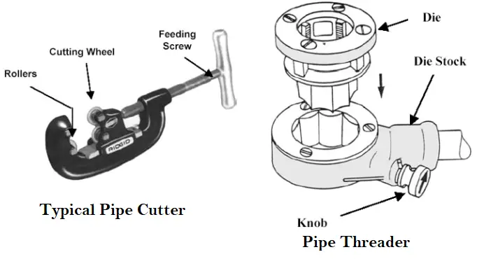
Pipefitters Tools
Typical Pipefitters tools
In the day to day work, every pipefitter uses various kinds of tools, popularly known as pipefitters tools. All these tools make a pipefitter’s life easy. A few of such commonly used pipefitters tools are listed below for reference:
Pipefitters normally get their huge experience from apprentice on-the-job training programs. The formats of the pipefitter’s training programs vary a little from country to country but most of them cover the basic piping details. Most of this training discusses the following:
Basic Technical mathematics for pipefitters
Inch and Metric systems of measurement
Pipe system types and design
Equipment, Tools, and materials used in Piping
Technical Drawings and Symbols and interpret them for pipe fabrication
Pipefitters Handbook explains all the important aspects of a pipefitter’s work. This book is a ready reference to gain knowledge to work in the pipefitters trade. Even though on-the-job training is the main aspect of a pipefitters experience, this pipefitters handbook is a good companion for a pipefitter. Various authors have shared their lifelong experiences to make the reader more knowledgeable and learn from the author’s viewpoint.
Difference Between Plumber and Pipefitter
The term plumbing and pipefitting are sometimes used interchangeably by many users, but both are not the same even though both work with piping systems. Both Plumber and Pipefitter a profession are different as mentioned below:
Plumber
Pipefitter
A plumber’s work revolves around public utility systems.
Pipefitters handle a wide range of complex piping systems.
Their main product is water, sewer, and wastewater systems
Pipefitter work with pipes handling steam, crude, and various other process fluids at high temperatures and pressure.
They work in buildings; both residential and commercial.
Pipefitters work in industries.
Lower end skills
Higher-end skills like pipe bending, threading, welding, grinding, etc.
Less Hazardous
Highly Hazardous
Less challenging job
Highly challenging and risky jobs.
Salary less
More Salary
Materials are normally copper and PVC
Carbon steel, stainless steel, and other alloys.
Plumber vs Pipefitter
Overview of Lateral Buckling and Upheaval Buckling of Pipelines
Long pipelines are often subjected to lateral and upheaval buckling. Both upheaval and lateral buckling can induce excessive bending stresses in the pipeline that may lead to pipeline failure. In January 2000, the 1.3 million liters of oil spill in Guanabara Bay, Brazil was initiated due to the lateral buckling phenomenon that caused the rupture of the offshore pipeline wall. Such consequences can be prevented, if the pipeline (both onshore and offshore) is designed to take care of the lateral and upheaval buckling phenomenon.
What are Lateral Buckling and Upheaval Buckling?
A pipeline traveling long distances transporting fluids under pressure and temperature is a slender structure. Both, temperature and internal pressure cause pipeline longitudinal expansion. Surface friction acts against this expansion restraining it which generates compression stresses in the pipeline wall that eventuates in buckling. There are two types of Buckling; Lateral Buckling and Upheaval Buckling.
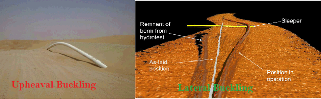
A surface-laid pipeline resting on the sand or seabed buckles laterally in the horizontal plane and this is called lateral buckling. On the other hand, a pipeline in a trench or sometimes buried pipeline undergoes buckling in the vertical plane, known as upheaval buckling. Both lateral buckling and upheaval buckling are highly sensitive in presence of local geometric imperfection.
As you might have gone through the previous article regarding the “Stress Analysis for Surface laid pipelines”, one of the Points of consideration during the analysis is the LATERAL / UPHEAVAL BUCKLING of the pipelines. The problem of upheaval / lateral buckling of the pipelines not only occurs naturally for the offshore (subsea) pipelines but also for the onshore pipelines at the Gathering and Injection lines of Oil and Gas production fields. In this article, we will explore the causes and the optimizations which could be implemented to avoid Upheaval / Lateral Buckling.
Lateral Buckling and Upheaval Buckling
Causes of Lateral and Upheaval Buckling
When a pipeline is under operation at a temperature and pressure higher than ambient, it will try to expand. If the line is not free to expand, the pipe will develop an axial compressive force. If the force exerted by the pipe on the soil exceeds the vertical restraint against uplift movement created by the pipe’s weight, its bending stiffness, and the resistance of the soil cover, the pipe will tend to move upward, and considerable vertical displacement may occur. The pipeline response may then be unacceptable because of excessive plastic yield deformation. Upheaval buckling is hence a failure mode that has to be taken into account in the design of trenched and buried pipelines.
The buckling in the lateral direction is most probable when the pipelines are laid on a flat area or bund area (SABKHA area as it is also known in a desert) for sabkha areas and when it is not provided with sufficient lateral resistance. However, when the pipelines are buried in a normal trench, the soil constraints in the lateral direction are high due to a large mass of soil, and chances of lateral buckling are not present.
Upheaval Buckling Calculation
The calculation for the upheaval buckling is based on the technical paper “About Upheaval and Lateral buckling of embedded pipelines” by Dr. K. Peters (3R International Edition 2006) for the underground pipelines and flowlines.
Based on the calculations, the maximum allowable overbend angle, in 12m of pipe length (Cold bend length considered in Pipelines), along the pipeline route and other calculation parameters are specified in the applicable calculation reports and the drawings. The calculations can also be done with the development of programs in ‘Mathcad,’ or equivalent software based on Dr. K. Peter’s technical paper as mentioned above.
The calculations model is carried out in 2- phases,
Phase 1: Calculation is done based on the topographically surveyed pipeline corridor profile
Phase 2: The verification phase for the design model is based on the actual survey for the top of the pipe in the trench after lowering and before back-filling.
Lateral Buckling Resistance in SABKHA
A lateral force that required resisting lateral buckling can be calculated as per calculations mentioned in “Technical Paper about Upheaval & Lateral Buckling of Embedded Pipelines” while the allowable lateral bend angle can be also calculated in a similar way to the allowable over-bend angle as explained above with the difference being using the lateral soil resistance. However, in most cases, the change in direction will be exceeding any allowable lateral bend angle, and hence the lateral berm reinforcement at the change of direction shall be provided based on the study done by K. TERZAGHI in Theoretical Soil Mechanics.
Extra Soil Cover/Berm Reinforcement Material
In case of upheaval buckling analysis proves that an extra soil cover is required at any location on the pipeline route and also if berm reinforcement is required to resist lateral buckling, gatch material shall be used with the required stabilization and proper slope (1:2) so that it shall not be blown away by wind effect across pipeline design life. Gatch material shall be the same as the approved for pipeline berm stabilization.
Guidelines and Recommendations
Suitable notes shall be included in the alignment sheets and the applicable drawings to take care of the maximum allowable over-bend angle, during construction. The alignment sheets also shall indicate the minimum elastic bend radius.
The buried pipelines shall be laid in such a way that the profile of the pipeline is smooth and without steep direction change. To achieve this cutting and filling or other suitable methods shall be done during pipeline construction.
For a given design parameter, there are two primary options to control the upheaval buckling. The first one is to ensure that the change of angle is within the calculated maximum allowable overbend angle limit for the given soil cover. The second one is to increase the soil resistance to increase the allowable overbend angle. To increase the soil resistance, the most direct method is to increase the soil cover
If the profile is such that the angle exceeds this limit when routing the pipeline, then suitable grading shall be done to keep the change of angle within limits, or alternatively, the allowable angle can be increased by increasing soil cover
Based on upheaval buckling calculations, the maximum allowable over-bend angle per 12 m pipe length shall be defined while pipeline corridor profile grading shall be carried out to keep the change of angle within such allowable over-bend angle limits.
The calculations for normal terrain sections in sandy areas shall be carried out for an effective height of 1 meter. Though the total effective height would be considered 1.9 m with 1 m as the normal depth of cover and 0.9 m soil cover in lieu of a total berm height of 1.0 meters.
In addition to the requirement in item 9.4 above during corridor grading, the construction team shall survey the top of pipe elevations immediately after lowering at intervals of 100 meters and 10 meters intervals at a change of directions for a reasonable distance on both sides. This top of the pipe shall survey shall be carried out for the full entire pipeline in sections before backfilling and shall be completed for the full pipeline length and submitted to the stress engineer for upheaval buckling verification after laying.
Along with this document, the construction shall refer to relevant documents regarding stress analysis and the maximum allowed angle for field bends.
If two or more pipelines are laid in the same trench or are in the same corridor with the same grading, the maximum allowable overbend angle shall be the lowest of all the individual maximum overbend angles.
During the construction, the contractor shall give special attention to rough sections of the route identified in the alignment sheets and shall grade such rough sections suitably in line with the calculation results. This will make sure that during final buckling checks additional cover if required shall be minimum.
Conclusions
As per past experience, upheaval buckling would be expected at locations with less vertical resistance to axial compressive force in the pipeline sections such as straight sections between nearby road crossings, vertical/ horizontal overbend angles higher than allowed buckling angles, interface between sabkha and non- sabkha areas, at both sides of road crossings, etc.
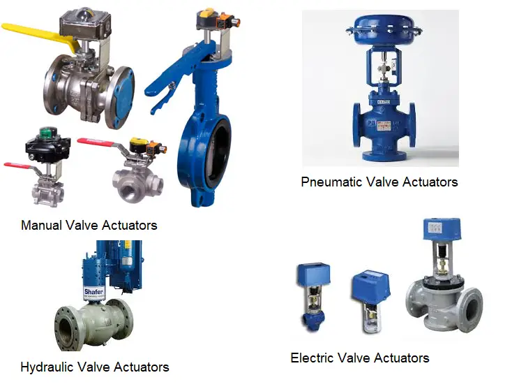
An actuator is a machine component that is used for moving and controlling a system or mechanism. To perform its operation, An actuator needs a control signal and a power source. They are widely used in valves, gates, conveyors, automatic control systems, etc. A valve actuator is a pneumatic, hydraulic, or electrically powered device that supplies force and motion for opening and closing a valve. The actuators can only open and close the valve or enable intermediate positioning. Some valve actuators contain switches or other means of remotely displaying the valve position. They are available in a variety of sizes. Commercial actuators basically perform any of the two functions listed below:
Applying a force or torque for lifting, turning, or forming.
Types of Actuators
Depending on the motion that actuators provide to the valves, two types of actuator mechanisms are available:
Rotary Actuators, and
Linear Actuators
Rotary actuators produce the rotating motion to operate valves like a ball, butterfly, and plug valves. On the other hand, Linear actuators convert hydraulic, pneumatic, or electric energy into linear motion to operate valves like gate valves, globe valves, pinch valves, etc.
Based on the power source the actuators use, four types of actuators are available in industrial applications:
Manual
Pneumatic
Hydraulic and
Electric Actuators
Fig. 1: Types of Valve Actuators
Manual Actuators
Manual Actuators are mechanical devices consisting of hand-operated knobs, levers, or wheels. They are unpowered tools and are used primarily in commercial applications for precise positioning.
Pneumatic actuators
Pneumatic actuators use the energy of compressed air to generate rotary and linear movements to operate valves and dampers. In the broadest sense, an air cylinder is a pneumatic actuator. Most pneumatic actuators use a few standard components which are easy for technicians to maintain
Motion control applications that use rotary pneumatic actuators generally fall in rack and pinion or paddle designs. Double-acting rack and pinion arrangements are often used. Multi-position, three, four, or five-stop actuators are often used for sequential assembly operations. The rotary actuators can also be used for indexing, stepping, picking up, and placing movements.
Pneumatic linear actuators are used in ascending stem valves to directly actuated gate valves, globe, etc. Two types are usually used, the diaphragm and the piston. Membrane styles are popular because their large surface area can generate tremendous force at moderate air pressure. The membrane is a rubber membrane, the edge of which is sealed with the outer housing of the actuator.
The air pressure moves the membrane up or down against the spring pressure, depending on whether the actuator is designed in such a way that it cannot be opened or closed. The stroke lengths are generally shorter than for piston valves, where the strokes depend only on the length of the cylinder and not on the stretch that the diaphragm can tolerate. Piston actuators can be sized to produce an adequate actuation force based on the available air pressure and can be made in double-acting spring return types. Some linear actuators use the familiar air springs instead of membranes. Pneumatic modulating valves are particularly effective because their speed is adjustable.
Advantages of Pneumatic Actuators:
The main advantages of pneumatic actuators are:
Provides more power than electric actuators.
An ideal choice for a site with many modulating valves
Medium fast to fast response. Normally they are faster than most electric motor actuators.
Safe type of power with a very low explosion risk.
Disadvantages of Pneumatic Actuators:
There are a few drawbacks of pneumatic actuators as listed below:
The requirement of an air compressor can increase the cost.
Compressors, dryers, and pneumatic actuators need to be maintained from time to time.
Leakage can occur at compressed air fittings
Hydraulic Actuators
Hydraulic actuators are devices that use the pressure of a liquid to operate the equipment. The normal liquid is a fire-resistant and stable oil that can work over a wide temperature range. Hydraulically powered devices and systems vary from very simple ones to others that are complex.
Working of Hydraulic Actuators:
All hydraulically operated devices do one of two things:
move fluid within a space with two or more movable surfaces, like in a hydraulic jack; or
confine it inside a system where hydraulic fluid is pumped so it can do useful work.
They rely on a basic fact about liquids: the volume occupied by the trapped hydraulic fluid cannot change because it is incompressible. Hydraulic actuators provide more power than any other type of actuator. Also, they provide a faster response and are compact in design. Hydraulic actuators and essential components like pumps, connected pipes, and fluid tanks are often part of a “turnkey” system.
Advantages of Hydraulic Actuators:
They can generate substantial power
Fast-acting
Compact Design
Depending on the application, hydraulic actuators need to be sized.
Disadvantages of Hydraulic Actuators:
Frequent maintenance required
Energy inefficient
Expensive
The operation can be noisy
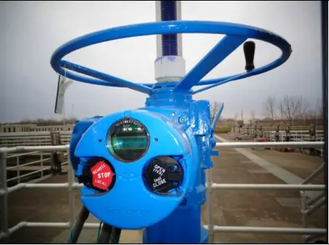
Electric actuators or Electric Motor Actuators
Electric Actuatorsare electromechanical devices used to remotely control quarter-turn valves such as ball and butterfly valves. Compared to their pneumatic and hydraulic counterparts, electric valve actuators offer a more efficient, cleaner, and quieter method of valve control. They can be purchased as a package with the valve or as a separate unit.
Electric Motor Actuators are self-contained units used to operate a final control element or load. They serve various purposes:
Convert the rotation of the motor’s shaft to a straight-line movement of a final control element or load through a gearbox, or a mix of gears and linkages.
Convert the rotation of the motor’s shaft to a lower speed through a gearbox for the final control element or operated device.
Position the vanes of a damper through a connecting linkage between the motor and the damper. Sometimes more than one linkage is used.
Electric motor actuators have many of the same components, such as a starter and an overload with motor cutoff contacts, that Motor Control Center compartments have for loads like pumps. Most electric motor actuators have external controls such as Open, Close, and Stop push buttons, and a Local-Off-Remote switch.
Fig. 2: Typical Electric Actuators
Common electric valve actuators have a 2-point control or a 3-point control, but both have 3 wires.
Types of electric valve actuators
1. 2 Point Control valve Actuators: The three wires are for +, -, and one control wire. To turn the valve, the control cable must be powered to open and not to close, or vice versa. Without the power to the entire device, the valve will remain in the newest position. For example, JP Fluid Control’s AW1-R series uses this open/close wiring scheme.
2. 3-point control valve actuators: All three wires are for – and two are for +. Therefore, the two control signals can open or close the valve, depending on which one is being powered. The 3-point control also offers the option of intermediate stops (partially open). The two control cables should never be powered at the same time; otherwise, the actuator will be damaged. For example, JP Fluid Control’s AW1 series uses this 3-point wiring scheme
Advantages of Electric Actuators:
Provides good reliability
Economic
Easy installation and operation with negligible maintenance.
Accurate control mechanism.
Low power consumption
Disadvantages of Electric Actuators:
Limited power capability.
In case of power failure, the valve may not automatically revert to a safe position.
For larger control loops, they tend to be slower
Pneumatic actuators vs electric actuators
A few points to consider while comparing the pneumatic actuators with the electric valve actuators.
Temperature range:
Both pneumatic and electric actuators can be used in a wide temperature range. The standard temperature range of a pneumatic actuator is -4 to 174 ° F (-20 to 80 ° C) but can be extended to -40 to 250 ° F (-40 to 121 ° C) with optional seals, bearings, and grease. If control accessories (limit switches, solenoid valves, etc.) are used they may not have the same temperature rating as the actuator and this must be taken into account in all applications. In the case of low-temperature applications, the quality must be taken into account and the supply air must be taken into account in relation to the dew point. The dew point is the temperature at which condensation occurs in the air.
Condensate can freeze and block the air supply lines, which can cause the actuator to malfunction. Electric actuators are available in a temperature range of -40 to 65° C. When used outdoors, an electric drive must be sealed off from the environment to prevent moisture from penetrating the internal operation. Condensation may still form inside if it is removed from the power supply line, which may have caught rainwater prior to installation. Because motors heat the interior of the actuator housing during operation and cool when it do not, temperature fluctuations can cause “breathing” and condensation in the surrounding area. For this reason, all the electric actuators used outdoors must be equipped with heating.
Dangerous areas:
It is sometimes difficult to justify using electric actuators in a hazardous environment. However, if compressed air is not available, or if a pneumatic actuator does not have the required operating characteristics, an electric actuator with properly rated housing can be used.
Presentation properties:
Before deciding on a pneumatic or electric actuator for valve automation, there are a few key performance characteristics to consider.
Duty cycle:
Pneumatic actuators have a duty cycle of 100 percent. The harder you work, the better you work. Electric actuators are typically available with 25 percent duty cycle motors. This means that the motor has to be idle frequently to avoid overheating in high-cycle applications. Since most automatic on / off valves remain inactive, 95 percent of duty cycle time is typically not an issue. With optional motors and/or capacitors, an electrical actuator can be upgraded to a pulse duty factor of 100 percent.
Modulate control:
Since electric actuators are gear motors, it is impossible to drive faster without changing gears. A pulse circuit can optionally be added for slower operation. In modulating operation, an electric actuator interacts well with existing electronic control systems and makes electro-pneumatic controls superfluous. A pneumatic or electro-pneumatic positioner is used with pneumatic actuators to provide a means of controlling the position of the valve.
Torque to-weight ratio:
Electric actuators have a high torque-to-weight ratio of more than 4,000 lbf.-in. (450 Nm). Pneumatic actuators have an excellent torque to weight ratio below 4,000 lbf.-in.
Cruise control:
The ability to control the speed of a pneumatic actuator is a key design advantage. The easiest way to control the speed is to insert the actuator with a variable opening (needle valve) into the air pilot’s outlet opening.
How does an actuator work?
It is basically a motor that converts energy into torque. This torque controls a mechanism or a system where the actuator has been incorporated. It helps in introducing or preventing the motion. It runs on electricity or pressure. The control system can be controlled mechanically or electronically, software-driven, or human-operated. They work because of the work done by the rotor and stator assemblies, also known as the primary and secondary windings within the motor. Voltage is applied to the primary assembly which results in inducing the flow of current to the rotor assembly, or the secondary winding. The interaction of these two creates a magnetic field that results in motion.
The working of actuators differs slightly based on their types. Pneumatic actuators work using the pressure of air and hydraulic actuators work using liquid pressure.
A valve drive can simply be defined as a black box with a signal or a power supply via air or oil pressure that creates a stop for the valve movement as an output. The quality of a valve depends on many parameters such as metallurgy, mechanical resistance, machining, etc. The performance of a valve is highly dependent on its actuator. It is important to consider the factors you are considering: frequency of operation, ease of access, and critical features.
Parts of a Valve Actuator
An actuator is connected to and works with two parts: the valve body and the valve pilot.
It consists of several parts including A bonnet, adjusting screw, engine valve spring and diaphragm, vent plug, yoke, upper spindle, clutch block, and drive indicator.
Actuators can automate valves so that no human interaction with the valve package is required to operate the valve. They can be remotely controlled and act as shutdown mechanisms in an emergency that would be dangerous for humans. It is a mechanism for controlling the energy supply. The source can be hydraulic pressure, pneumatic pressure, or electrical current.
Where an actuator should be used?
The actuators are ideal for installations where human interaction is impossible or dangerous, eg. space installation or any location that prevents access to humans as valve actuators.
Compact actuators are used in FPSO or other locations where space and weight are critical. These actuators are designed to offer the powerful torque and thrust of their larger counterparts, but with a smaller footprint to install.
Subsea actuators are designed to withstand the low temperatures, extremely high pressures, and remote access capabilities of subsea equipment.
Ball valve actuators
A ball valve is a shut-off valve that controls the flow of a liquid or gas by means of a rotary ball having a bore. They are characterized by a long service life and provide reliable sealing over the life span, even when the valve is not in use for a long time. They are more resistant to contaminated media than most other types of valves. In special versions, ball valves are also used as control valves.
Types of ball valve actuators
1. Standard:
These are the most common types of ball drives. They consist of housing, seats, a ball, and a lever for rotating the ball. These include ball valves with two, three, and four connections.
2. Hydraulics:
Hydraulic ball valves are specially designed for hydraulic and heating systems due to their high operating pressure and their resistance to hydraulic and heating oil. These valves are made of steel or stainless steel.
3. Flanged:
These valves offer a high flow rate because they typically have a complete connection structure. When choosing a flange ball valve, in addition to the pressure rating, you should also check the compression class of the flange, which indicates the highest pressure that this type of connection can withstand. These ball valves are equipped with two, three, or four connections.
4. Ventilated:
Ventilated ball valves look almost exactly the same in design as conventional 2-way ball valves. The main difference is that when the outlet is closed, it vents to the environment. This is achieved through a small hole drilled into the ball and valve body. When the valve closes, the openings align with the outlet opening and release the pressure. This is particularly useful in compressed air systems where pressure relief provides a safer working environment.
Control valve actuators
The purpose of a control valve actuator is to provide the motive force to operate a valve mechanism.
Types of control valve actuators–
1. Pneumatic control valve: This type has a flexible membrane with pressure applied against the spring force of the actuator. When the control system sends its signal, the actuator generates a force that exceeds the force of the spring and moves the actuator shaft
2. Electric control valve: This actuator has a motor and a gearbox to generate torque that moves the valve up and down. We can find this type in linear and rotary control valves.
3. Electro-hydraulic valve actuator: This type mixes electrical signals and hydraulic units to operate the valve. The signal controls the flow of oil to open and close the valve using a flap nozzle system similar to a pneumatic system.
4. Hydraulic control valve actuator: This works very similarly to a pneumatic actuator and can be used for both linear and rotary control valves. However, it uses liquid instead of air to create force in your system.
How to choose the right actuator?
Selection of the best actuator type for any application is dependent on many factors including:
Operational characteristics and functions like actuation speed, cycle life, the requirement of fail-safe, etc.
Parameters to consider while selecting an actuator are,
1. Valve Size and Torque: Large, high-pressure class valves require high torque to operate. Choosing a very large pneumatic actuator for such a large valve is not economical. In this case, a hydraulic drive is recommended.
2. Failure mode: In contrast to electrical actuators, pneumatic and hydraulic actuators remain in the open or closed position during a power failure. These types of valves are spring-loaded, i.e. in the event of a power or signal failure, the spring returns the valve to a predefined safe position. Therefore, for example, electric actuators are not suitable for shut-off valves that must be completely closed when power is available.
3. Operating Speed - Electric actuators operate valves more slowly than pneumatic and hydraulic actuators. Therefore, an electric actuator may not be suitable if the valve is expected to operate at 1 in / sec or greater.
4. Frequency and Ease of Use: It is common to use electric actuators for certain large valves that are operated frequently rather than manually to facilitate operation. For example, it is proposed to equip a manual 20-inch class 300 ball valve with frequent operation with an electric actuator for ease of use only.
5. Control accessories: In contrast to pneumatic and hydraulic actuators, the control accessories for electric actuators are built into the actuator. In fact, electrical actuators do not require space for control accessories, which is an advantage. Hydraulic actuators have larger control panels compared to pneumatic actuators.
6. Hazardous Areas: In some cases, the use of electric actuators may be restricted in a hazardous environment. Different hazard zones and classes are defined depending on the presence of flammable gases or vapors that can limit the use of electric actuators.
7. Cost: Electric actuators are the cheapest type of actuator, hydraulic actuators are the most expensive, and tires are in the middle.
8. Power Source Availability: A hydraulic actuator cannot be used in a facility if a high-pressure oil source is not available.
Meaning of Ultrasonic Testing | Ultrasonic Testing of Welds
Ultrasonic testing, often abbreviated to either UT or Ultrasonic NDT, is an umbrella term for a number of non-destructive techniques used to detect the characteristics of a material. This type of testing involves using high-frequency ultrasound sound waves for the purposes of characteristic investigation. In this article, the characteristics of ultrasonic testing of welds will be discussed.
Non-destructive ultrasonic testing was first explored as early as 1942, by Dr. Floyd Firestone. He created a method to detect irregularities within the mass of material, even when they were invisible on the surface. Since then, other researchers have continued to refine the process, as well as expand the range of its utility.
What is Ultrasound?
Ultrasound refers to a frequency level that human beings are incapable of hearing. The overall ultrasound frequency range is 20,000 Hertz and above. In welding ultrasonic testing, the frequency used typically falls within the range of 500 Kilohertz to 20 MegaHertz.
Types of Ultrasonic Waves
There are four main types of waves used in non-destructive techniques like ultrasonic testing
1. Longitudinal waves
Longitudinal waves oscillate in the same direction as the propagation of the wave. The density of these waves fluctuates as they move. These waves can travel through liquids, gases, and solids through movements of compression and expansion.
2. Shear waves
Shear waves are also called transverse waves. In this type, the particles vibrate and move at a right angle to the direction of the wave’s propagation. These waves are stronger in solids than in other states of matter, though they are generally weaker when compared to longitudinal waves.
3. Surface waves
Surface waves are also called Rayleigh waves. The particle vibration of these waves is in the form of an elliptical orbit. These waves are extremely sensitive to surface irregularities and defects. They are also good at following curves and are useful in places where other waves cannot reach them.
4. Lamb waves
Lamb waves are also called plate waves. They are similar to Rayleigh waves, but cannot be generated in pieces that are thick. They require flat pieces that are only a few wavelengths thick.
Equipment/Tools Required for Ultrasonic testing
Transducer:
In ultrasonic testing, a transducer is a device that converts electrical energy into sound waves that travel through the piece being inspected and vice versa. Transducers are available in a variety of frequencies for different test pieces. There are many types of transducers, divided broadly into contact and non-contact devices.
Contact transducers require direct contact with the test piece. The shape and material of the transducer can vary. Also, the type, temperature, and thickness of the test piece will dictate the type of transducer being used, e.g. delay line transducer for thin pieces, dual line transducer for corroded or extremely hot pieces, etc. Contact transducers require couplants to enable the transmission of energy from the transducer to the surface of the test piece. Couplants are used to displace the air; they are usually in liquid or gel form.
Non-contact transducers or electromagnetic acoustic transducers do not require direct contact with the test piece to inspect it thoroughly. These transducers can be used in harsh temperatures and on most metals. As there is no physical contact, these transducers do not require couplants to facilitate transmission. However, unlike contact transducers, these devices are electromagnetic in nature and can therefore only be used on metallic or magnetic test pieces. Non-contact transducers are often used in welding ultrasonic testing.
Diagnostic machine:
A machine that records the signal of the pulse and the resulting echoes. These machines are also used to analyze the received data in different ways. The machine used will depend on the type of inspection being conducted, e.g. thickness gauging, flaw detection, etc. These machines can be either manual or automated, and either portable or not. Different types of diagnostic machines will be required for contact or immersion testing. The information presented on the equipment will also differ. There may or may not be a digital graphic of the signal. The machine must be calibrated on the basis of the properties of the test piece before it can be used for inspection.
Pulser and Receiver:
This is a device that can produce and receive ultrasonic energy of high frequencies. It is the connection between the transducer and the diagnostic machine. The pulsar emits controlled bursts of energy. The receiver section transports the echoes produced by the transducer to the diagnostic machine.
Ultrasonic Testing Procedure
Once the pulse receiver is connected to the transducer and a diagnostic device, the process of inspection begins. The active element of the transducer is passed over the piece being inspected.
There are multiple methods to carry out ultrasonic testing. These methods can be classified into three main categories:
1. Method of receiving ultrasound
a. Reflected transmission
In the reflected transmission method, a pulse of energy is sent through the test piece that continues until it hits a different medium, i.e. a border. It is usually the back wall of the piece. A reflected pulse or an echo is then emitted from the back wall. The intensity of the pulse and the echo are noted. In case of a crack or imperfection, the pulse will not reach the back wall, it will be reflected from the location of the imperfection, resulting in an echo signal of lower intensity.
b. Through/attenuated transmission
In this method, an ultrasound is sent through one surface of the test piece and is received by a separate receiver on the other side of the piece. In case of imperfection, the intensity of the sound received will be lower than usual. For this method, at least two sides of the test piece must be available. Also, this type is better for pinpointing the location of the crack, but the depth at which it is located can remain unclear.
2. Angle of sound waves
a. Normal beam
This refers to the angle at which the pulse is introduced to the test piece. A normal beam is a 90-degree angle. The normal beam method can be used for test pieces that are flat or smooth, with no unwieldy obstructions.
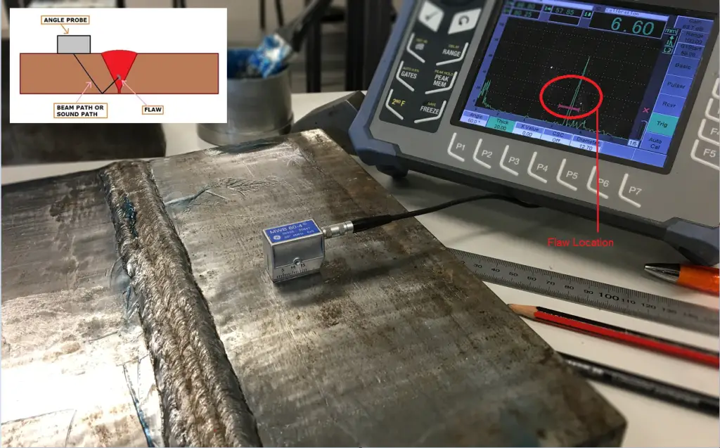
b. Angle beam
In this method, the pulse is emitted into the test piece at any angle other than 90 degrees. For this method, an angled transducer will be required for an easier sound introduction. This method is useful when the best way to get the largest reflection is at a diagonal. It is also useful in case some part of the test piece is obstructed, and normal beam inspection is not possible. This method is useful for determining the thickness of the test piece and the depth of the imperfection.
3. Method of coupling
a. Contact
In contact testing, a couplant is applied between the transducer and the test piece to reduce the air and increase the intensity of the sound waves.
b. Immersion
In immersion testing, the test piece and the transducer are both immersed in a bath. In this type of testing the water acts as the couplants. The movement of the transducer is smoother in this method of ultrasonic testing.In this method, direct physical contact between the transducer and the test piece is not required. Also, a specific immersion transducer is to be used for this method.
c. Non-contact
This is a type of testing that does not require contact and operates on principles of electromagnetism mechanics.
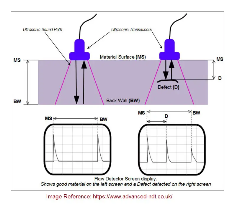
Fig. 1 shows the principle of Ultrasonic Testing.
Fig. 1: Principle of Ultrasonic Testing
An ultrasound transducer or ultrasonic probe sends a sound wave into a test material. Two indications are received from each probe; the first one is from the initial pulse of the probe, and the second one is from the back wall echo. If there is any defect, it creates a third indication (See the right side display in Fig. 1) and simultaneously reduces the amplitude of the back wall indication. The depth at which the defect is present can easily be calculated by dividing the length D by the length between MS and BW.
Common Data Formats for Ultrasonic Testing
1. A Scan
The A-Scan presents the data as the strength of the signal received and the time it took to receive it. The depth and size of the flaw can be determined using this type of scan by comparing the size and position of the signal on the scan.
2. B Scan
The B Scan is a cross-sectional scan of the test piece. In this type of presentation, the time taken for travel is presented with its distance to the transducer.
3. C Scan
The C Scan is a plane view of the test piece, with a sign indicating the position of the detected flaw. The plane view can be from the top, bottom, or side, depending on the position of the transducer.
With automated diagnostic machines and interfaces, all these types of charts are created automatically to provide an accurate analysis of the test piece. With progress in the field of ultrasound imaging, the quality of data presented has become more and more detailed. Now, it is possible to spot even minuscule irregularities.
Materials to be used on
Ultrasonic testing can be conducted on a variety of materials. It is applicable to most metals, alloys, and composites, as well as concrete, ceramics, plastic, and even wood. Ultrasonic testing is even used in the medical field, e.g. sonography.
Ultrasonic Testing of Welds
Welding is the process of fusing at least two parts by using methods like heat and/or pressure. Though welding is most commonly used on metals, it is also possible to weld thermoplastics and wood. A welding project that is complete is called a weldment. A weldment mainly consists of two materials: a parent component and a consumable. A parent component is the material of the parts that are going to be joined. A consumable, sometimes called a filler, is the material that is used to fuse the parts together.
Weldments can be either homogeneous or heterogeneous. Homogenous welds are those where the material of the consumable is compositionally similar to the material of the parent component. Consequently, in heterogeneous welds, the two materials are compositionally different. While homogenous weldments are generally preferred, heterogenous weldments have to be constructed in cases when the parent component is brittle or otherwise unstable.
Since welding is a high-heat and pressure process, it requires skill and practice to produce smoothly fused weldments that are flawless. Mistakes like hurrying the process, or letting the metal cool too soon can lead to cracks or other imperfections, which are sometimes located inside the weldment. They cannot be spotted from the surface but can compromise the strength of the welded product. This is why ultrasonic testing of welds is a good way to determine the quality and craftsmanship of a weldment without disassembling it.
Fig. 2: Ultrasonic Testing of Welds
1. Ultrasonic Testing of Welds for Flaw detection
Ultrasonic testing in welding can be used to detect defects and irregularities in test pieces. As a non-destructive method, it is completely non-invasive. However, it can still provide extremely accurate readings of flaws that lie beneath the surface of the item:
a. Porosity
Pores are extremely small voids in a component. They are formed when gas gets trapped in welding metal as it is solidifying. Pores are either distributed evenly throughout an item or are concentrated on one part. Pores are mostly spherical, but they can also look elongated.
b. Slag inclusions
Slag inclusions are non-metallic solid substances that are stuck within the welded metal. If welding is done too fast, or at the wrong angle, slag inclusions are likely to occur. Unless they are at the surface, these inclusions are impossible to spot without testing.
c. Lack of sidewall fusion
Lack of the smoothening of the fusion between the metal used for welding and the parent metal is called lack of sidewall fusion. This can happen if the arc length is too big and the metal melts over the side.
d. Lack of inter-run fusion
This is when the weld metal does not fuse the previous weld bead adequately.
e. Lack of root penetration
When both sides of the joint’s root region remain unfused, it is called a lack of root penetration.
f. Undercutting
An undercut is a type of welding defect where the cross-sectional thickness of the metal is reduced, thus lowering the strength of the weld and of the item itself. In industrial settings, equipment that has undercutting can be a safety concern and needs to be replaced.
g. Longitudinal or transverse cracks
Longitudinal cracks run across the center of the weld, while transverse cracks run perpendicular through the axis of the weld.
2. Ultrasonic Testing in Welding for Thickness detection
An ultrasonic thickness gauge is used to determine the thickness of an item by using sound waves to determine the time it takes for the sound waves to produce an echo. The thickness of an item is an important characteristic: the thickness of medical tubes and contact lenses needs to be standardized, and the thickness of heavy machinery is not only a matter of having no variables, but it is also a matter of safety. Also, ultrasonic testing of welds to determine their thickness is a great way to keep track of the corrosion levels of pipes and tanks.
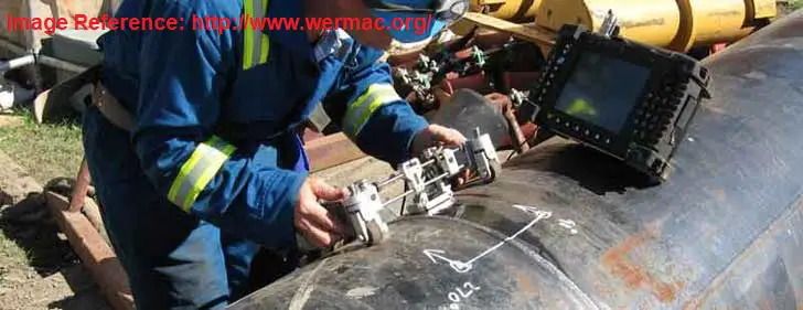
Fig. 3 below shows ultrasonic testing in the welding of pipe to detect any flaw in the piping weld.
Fig. 3: Ultrasonic Testing of welding in pipes
Advantages of Ultrasonic Testing
Detection of deep-rooted invisible flaws: Some flaws are not on the surface of an item. With ultrasonic testing, it is possible to identify flaws deep within the mass of the test piece.
Detection of minuscule flaws: Ultrasonic testing can identify the presence of tiny flaws as well as big ones. With the equipment required for this method being upgraded constantly, the preciseness level is only increasing further.
Possible even with only one surface: Some items being tested may be too corroded to move, welded into the wall, etc. In cases like this, it is not possible to move the item for testing. Thankfully, ultrasonic testing is possible even when the examiner only has access to one surface of the test piece.
Accuracy at determining depth and thickness: Ultrasonic testing equipment can identify the precise location of a crack, as well as determine how big it is, without having to use invasive methods.
May even determine the nature of the flaw: In some cases, it is also possible for an experienced examiner to identify the cause or origin of the flaw by analyzing the readings on the testing equipment.
A non-destructive and safe method for inspectors: It is a completely non-destructive method and does not cause any harm to the items being tested. Additionally, it is a safe method for workers to examine the item, as it does not pose any health or safety concerns for the examiner.
Highly automated: Diagnostic machines are now highly automated and capable of performing any calculations the examiner might need. Also, the machines not only organize the data but also present it in all three data formats commonly used in ultrasonic testing.
Immediate results for quick decisions: The results of ultrasonic testing are instantly available to the examiner. This means that flaws are identified immediately, and consequent decisions can be taken without delay.
Disadvantages of Ultrasonic Testing
Manual operation of the sensitive probe requires practice: As the probes are sensitive, they need to be handled with extreme care. This is because, even with couplants, probes can pick up a significant level of noise, which can hinder results.
Technical knowledge required: Ultrasonic testing can be confusing without at least a basic understanding of the topic. To carry out this task, personnel will have to be given some technical training in this field. They will also need to practice their application methods a lot.
Water-based couplants pose a danger to tested items, and need anti-freeze liquids: Water can be a danger to many items that are regularly tested using ultrasonic NDT. While it would be ideal for all test pieces to be water-resistant, this is not the case. And unfortunately, water-based couplants are the most common type of couplants. If they are to be used, it is advisable to use antifreeze on the item beforehand to prevent damage.
Equipment requires calibration, and thick test pieces will need multiple setups: The diagnostic equipment has to be calibrated according to the features of every test piece, which can be very time-consuming. In cases where the piece is too thick, the equipment will have to be set up multiple times for a single test piece.